CN215659448U - Toughened glass corner grinding device - Google Patents
Toughened glass corner grinding device Download PDFInfo
- Publication number
- CN215659448U CN215659448U CN202122326561.9U CN202122326561U CN215659448U CN 215659448 U CN215659448 U CN 215659448U CN 202122326561 U CN202122326561 U CN 202122326561U CN 215659448 U CN215659448 U CN 215659448U
- Authority
- CN
- China
- Prior art keywords
- sleeved
- toughened glass
- motor
- grinding disc
- rod
- Prior art date
- Legal status (The legal status is an assumption and is not a legal conclusion. Google has not performed a legal analysis and makes no representation as to the accuracy of the status listed.)
- Active
Links
Images


Abstract
The utility model relates to the technical field of toughened glass polishing, and discloses a toughened glass corner polishing device which comprises a conveyor, wherein the top of the conveyor is fixedly connected with a support frame, the middle part of the support frame is fixedly sleeved with a positioning frame, a bidirectional screw rod is rotatably sleeved in the positioning frame, and a sliding plate is slidably sleeved outside the positioning frame. This toughened glass corner grinding device, the operator can rotate the handle of two-way lead screw left end, drive two-way lead screw through the handle and carry out two-way rotation, two-way lead screw's rotatory two sliding plates of drive begin to be opposite direction movement, the removal of sliding plate drives mill pole and decides the mill pole and removes in step, reached convenient regulation from this and moved the effect of mill pole and deciding the mill pole interval, the manufacturing cost who has reduceed this device has saved the cost of labor that the operation was adjusted and was moved mill pole and decided the mill pole interval again promptly, the practicality and the convenience of this device have been improved.
Description
Technical Field
The utility model relates to the technical field of toughened glass grinding, in particular to a toughened glass corner grinding device.
Background
Toughened glass corner grinding device, the name of the name is exactly the equipment that polishes to toughened glass's edge deckle edge, this kind of grinding device is electronic polisher usually, the reciprocal electronic polishing polisher of electronic polisher full name (a file mill again), the finish machining and the surface finish that extensively are used for the mould trade handle, be the substitute of the pneumatic product of a section of the same kind, and the equipment that is used for toughened glass corner to polish has added the conveyer on the basis of using electronic polisher, be used for carrying out semi-automatic the polishing to toughened glass's edge.
Most toughened glass corner grinding device in the existing market, it polishes toughened glass through the compound mode of conveyer and electronic polisher, but the polisher under this kind of mode if will carry out the adjustment of mill interval according to toughened glass's width then need be through adding the computer of establishing and can realize, perhaps adopt artifical adjustment mill interval, like this or increase manufacturing cost or increase the cost of labor, and when carrying out the conveying to toughened glass through the conveyer, the rotation of transfer roller can lead to toughened glass to take place to deviate, make polisher idle running and can't carry out effectual polishing to toughened glass, we propose a toughened glass corner grinding device for this reason.
SUMMERY OF THE UTILITY MODEL
Aiming at the defects of the prior art, the utility model provides a toughened glass corner polishing device which has the advantages that the distance between the grinding discs can be conveniently adjusted and the toughened glass on a conveyor can be conveniently conveyed and limited through manpower according to the width of the toughened glass, and the problems in the background art are solved.
The utility model provides the following technical scheme: the utility model provides a toughened glass corner grinding device, includes the conveyer, the top fixedly connected with support frame of conveyer, the fixed cover in middle part of support frame has cup jointed the locating rack, the inside of locating rack is rotated and has been cup jointed two-way lead screw, the sliding plate has been cup jointed in the outside slip of locating rack, motor one is installed at the top of sliding plate, the fixed cover of output shaft of motor one has been cup jointed and has been moved the mill pole, the belt has been cup jointed in the outside transmission of moving the mill pole, inverter motor, two are installed at the top of support frame both sides inverter motor output shaft threaded rod's outside screw thread has been cup jointed motor two, the left inside fixedly connected with locating plate of conveyer, spacing frame has been cup jointed in the outside slip of locating plate.
Preferably, the movable grinding disc rod penetrates through the left side of the sliding plate, the bottom of the right side of the sliding plate is rotatably sleeved with the fixed grinding disc rod, and the fixed grinding disc rod is sleeved on the right side of the inside of the belt in a transmission mode.
Preferably, a hydraulic machine is installed at the bottom of the positioning frame, a pressing plate is fixedly connected to an output shaft of the hydraulic machine, a rubber disc is installed at the bottom of the pressing plate, and the left sides of the two sliding plates are respectively in threaded sleeve joint with the two sides of the bidirectional screw rod.
Preferably, a servo motor is installed outside the right side of the conveyor, a handle is installed at the left end of the bidirectional screw rod, and the sliding plate, the first motor, the movable grinding disc rod, the fixed grinding disc rod, the belt, the variable frequency motor and the second motor are arranged in two groups and are symmetrical left and right.
Preferably, the bottoms of the movable grinding disc rod and the fixed grinding disc rod are positioned at the interval of the conveying rollers of the conveyor, and the grinding discs at the bottoms of the movable grinding disc rod and the fixed grinding disc rod are higher than the conveying rollers.
Preferably, the height of the positioning plate is higher than that of the conveying roller, two groups of limiting frames are arranged, and the right ends of the two groups of limiting frames are fixedly connected to the left ends of the two groups of sliding plates.
Compared with the prior art, the utility model has the following beneficial effects:
1. this toughened glass corner grinding device, locating rack through cup jointing at the middle part of support frame, two-way lead screw and sliding plate, when needs are adjusted the interval of moving the mill pole and deciding the mill pole, the operator can rotate the handle of two-way lead screw left end, drive two-way lead screw through the handle and carry out two-way rotation, two-way lead screw's rotatory two sliding plates of drive begin to be opposite direction movement, the removal of sliding plate drives mill pole and decides the mill pole and removes in step, reached the convenient effect of adjusting and moving the mill pole and deciding the mill pole interval from this, the manufacturing cost who has reduceed this device has saved the cost of labor that the operation was adjusted and was moved mill pole and decided the mill pole interval again promptly, the practicality and the convenience of this device have been improved.
2. This toughened glass corner grinding device, through the locating plate at conveyer inner chamber left side fixed connection and with sliding plate fixed connection's spacing frame, when two-way lead screw carries out the interval of rotation regulation sliding plate through the manpower, the slip cup joints two outside spacing frames of locating plate and carries out synchronous regulation along with two sliding plates, after two spacing frames are fixed, can form the direction spacing to toughened glass, toughened glass can not produce the skew when the inside of two spacing frames conveys, the accurate nature of polishing of this device has been improved.
Drawings
FIG. 1 is a front view of the structure of the present invention;
FIG. 2 is a rear view of the structure of the present invention;
FIG. 3 is a front view of the structure of the present invention;
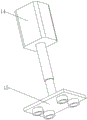
FIG. 4 is a side view of the hydraulic machine of the present invention.
In the figure: 1. a conveyor; 2. a support frame; 3. a positioning frame; 4. a bidirectional lead screw; 5. a sliding plate; 6. a first motor; 7. a movable grinding disc rod; 8. a fixed grinding disc rod; 9. a belt; 10. a variable frequency motor; 11. a second motor; 12. positioning a plate; 13. a limiting frame; 14. a hydraulic press; 15. pressing a plate; 16. a servo motor.
Detailed Description
The technical solutions in the embodiments of the present invention will be clearly and completely described below with reference to the drawings in the embodiments of the present invention, and it is obvious that the described embodiments are only a part of the embodiments of the present invention, and not all of the embodiments. All other embodiments, which can be derived by a person skilled in the art from the embodiments given herein without making any creative effort, shall fall within the protection scope of the present invention.
Referring to fig. 1, 2 and 3, a tempered glass corner polishing device comprises a conveyor 1, a plurality of groups of driving rollers are sleeved on the inner transmission of the conveyor 1 to play a role of conveying tempered glass, a supporting frame 2 is fixedly connected to the top of the conveyor 1, the supporting frame 2 plays a role of supporting a positioning frame 3 and a variable frequency motor 10, the positioning frame 3 is fixedly sleeved at the middle part of the supporting frame 2, a bidirectional screw 4 is sleeved on the inner rotation of the positioning frame 3, the bidirectional screw 4 ensures that the distance between two sliding plates 5 can be conveniently adjusted, the sliding plates 5 are sleeved on the outer sliding part of the positioning frame 3, the sliding plates 5 play a role of bearing a motor 6 and a fixed millstone rod 8, the motor 6 is installed at the top of the sliding plate 5, the motor 6 ensures that a movable millstone rod 7 can be driven to polish tempered glass corners, the movable millstone rod 7 is fixedly sleeved on the output shaft of the motor 6, the belt 9 is sleeved on the external transmission of the movable millstone rod 7, the belt 9 plays a role of linking two groups of movable millstone rods 7 and the fixed millstone rods 8, the variable frequency motors 10 are installed at the tops of two sides of the support frame 2, the variable frequency motors 10 ensure that the motors 11 can repeatedly polish the front and rear corners of the toughened glass, the motors 11 are sleeved on the external threads of the threaded rods of the output shafts of the two variable frequency motors 10, the motors 11 play a role of polishing the front and rear corners of the toughened glass, the positioning plate 12 is fixedly connected to the inside of the left side of the conveyor 1, the positioning plate 12 plays a role of containing the toughened glass, the limiting frame 13 is sleeved on the outside of the positioning plate 12 in a sliding way, the limiting frame 13 plays a role of limiting and guiding the toughened glass, the movable millstone rod 7 passes through the left side of the sliding plate 5, the fixed millstone rod 8 is sleeved on the bottom of the right side of the sliding plate 5 in a rotating way, and the fixed millstone rod 8 enhances the efficiency of polishing the corners of two sides of the toughened glass, the fixed grinding disc rod 8 is sleeved on the right side inside the belt 9 in a transmission manner, the servo motor 16 is installed outside the right side of the conveyor 1, the servo motor 16 plays a role of controlling the conveying of conveying rollers inside the conveyor 1, the handle is installed at the left end of the bidirectional screw rod 4 and facilitates an operator to control the bidirectional screw rod 4, the sliding plate 5, the first motor 6, the movable grinding disc rod 7, the fixed grinding disc rod 8, the belt 9, the variable frequency motor 10 and the second motor 11 are arranged in two groups and are bilaterally symmetrical, the bottoms of the movable grinding disc rod 7 and the fixed grinding disc rod 8 are positioned at the interval of the conveying rollers of the conveyor 1, the grinding discs at the bottoms of the movable grinding disc rod 7 and the fixed grinding disc rod 8 are higher than the conveying rollers, the movable grinding disc rod 7 and the fixed grinding disc rod 8 can polish corners at two sides of toughened glass while ensuring that the transmission of the conveying rollers is not blocked, the positioning plate 12 is higher than the conveying rollers, and the limiting frame 13 is arranged in two groups, the right ends of the two groups of limit frames 13 are fixedly connected with the left ends of the two groups of sliding plates 5.
Referring to fig. 4, a hydraulic machine 14 is installed at the bottom of the positioning frame 3, the hydraulic machine 14 plays a role in controlling the lifting height of a pressing plate 15, the pressing plate 15 is fixedly connected to an output shaft of the hydraulic machine 14, a rubber disc is installed at the bottom of the pressing plate 15, the rubber disc ensures that the tempered glass cannot be damaged while being fixed, and the left sides of the two sliding plates 5 are respectively in threaded sleeve connection with the two sides of the bidirectional screw 4.
The working principle is as follows: when the device is used, firstly, the handle at the left end of the bidirectional screw rod 4 is rotated according to the width of toughened glass to be polished, the rotation of the bidirectional screw rod 4 drives the two sliding plates 5 which are sleeved with the external threads at the two sides of the bidirectional screw rod 4, the movement of the sliding plates 5 drives the two groups of movable grinding disc rods 7 and fixed grinding disc rods 8 to synchronously move, when the distance between the movable grinding disc rods 7 and the fixed grinding disc rods 8 is adjusted to be equal to the width of the toughened glass, the rotation is suspended, meanwhile, the two sliding plates 5 drive the two limiting frames 13 fixedly connected with the left ends of the two sliding plates to synchronously move, the movement of the two limiting frames 13 also internally forms a guide space, the distance between the two limiting frames 13 is equal to the width of the toughened glass, when the toughened glass is fed, the two limiting frames 13 are just attached to the two sides of the toughened glass to form limiting guide to the toughened glass, so that the toughened glass cannot deviate during transmission, when toughened glass enters into two sets of insides of moving mill pole 7 and deciding mill pole 8, start hydraulic press 14, hydraulic press 14 drives clamp plate 15 and pushes down and carries out the pressfitting with glass fixed, the operation starter motor 6 of pause servo motor 16 simultaneously, it polishes to the both sides of toughened glass to drive mill pole 7 and decide mill pole 8 through motor 6, then start servo motor 16, continue conveying toughened glass, make toughened glass successively move to the below of two motors two 11, then start inverter motor 10 and motor two 11 and polish the corner around the toughened glass, can accomplish from this and polish all corners of toughened glass.
It is noted that, herein, relational terms such as first and second, and the like may be used solely to distinguish one entity or action from another entity or action without necessarily requiring or implying any actual such relationship or order between such entities or actions. Also, the terms "comprises," "comprising," or any other variation thereof, are intended to cover a non-exclusive inclusion, such that a process, method, article, or apparatus that comprises a list of elements does not include only those elements but may include other elements not expressly listed or inherent to such process, method, article, or apparatus. Meanwhile, in the drawings of the utility model, the filling pattern is only used for distinguishing the layers and is not limited at all.
Although embodiments of the present invention have been shown and described, it will be appreciated by those skilled in the art that changes, modifications, substitutions and alterations can be made in these embodiments without departing from the principles and spirit of the utility model, the scope of which is defined in the appended claims and their equivalents.
Claims (6)
1. The utility model provides a toughened glass corner grinding device, includes conveyer (1), its characterized in that: the top of the conveyor (1) is fixedly connected with a support frame (2), the middle part of the support frame (2) is fixedly sleeved with a positioning frame (3), a bidirectional screw rod (4) is rotatably sleeved in the positioning frame (3), a sliding plate (5) is slidably sleeved outside the positioning frame (3), a first motor (6) is installed at the top of the sliding plate (5), a movable grinding disc rod (7) is fixedly sleeved on an output shaft of the first motor (6), a belt (9) is sleeved on the outer part of the movable grinding disc rod (7) in a transmission manner, variable frequency motors (10) are installed at the tops of two sides of the support frame (2), a motor II (11) is sleeved on the outer threads of the output shaft threaded rods of the two variable frequency motors (10), the inner part of the left side of the conveyor (1) is fixedly connected with a positioning plate (12), and the outer part of the positioning plate (12) is sleeved with a limiting frame (13) in a sliding mode.
2. A tempered glass corner grinding device as claimed in claim 1, wherein: the movable grinding disc rod (7) penetrates through the left side of the sliding plate (5), the bottom of the right side of the sliding plate (5) is rotatably sleeved with the fixed grinding disc rod (8), and the fixed grinding disc rod (8) is sleeved on the right side of the inner portion of the belt (9) in a transmission mode.
3. A tempered glass corner grinding device as claimed in claim 1, wherein: the bottom of the locating frame (3) is provided with a hydraulic machine (14), an output shaft of the hydraulic machine (14) is fixedly connected with a pressing plate (15), the bottom of the pressing plate (15) is provided with a rubber disc, and the left sides of the two sliding plates (5) are respectively sleeved on the two sides of the two-way screw rod (4) in a threaded manner.
4. A tempered glass corner grinding device as claimed in claim 1, wherein: the outer mounting on conveyer (1) right side has servo motor (16), the handle is installed to the left end of two-way lead screw (4), sliding plate (5), motor (6), move mill pole (7), decide mill pole (8), belt (9), inverter motor (10), motor two (11) are equipped with two sets ofly altogether, and bilateral symmetry.
5. A tempered glass corner grinding device as claimed in claim 1, wherein: the bottom of the movable grinding disc rod (7) and the bottom of the fixed grinding disc rod (8) are positioned at the interval of the conveying rollers of the conveyor (1), and the grinding discs at the bottoms of the movable grinding disc rod (7) and the fixed grinding disc rod (8) are higher than the conveying rollers.
6. A tempered glass corner grinding device as claimed in claim 1, wherein: the height of the positioning plate (12) is higher than that of the conveying roller, two groups of limiting frames (13) are arranged, and the right ends of the two groups of limiting frames (13) are fixedly connected to the left ends of the two groups of sliding plates (5).
Priority Applications (1)
| Application Number | Priority Date | Filing Date | Title |
|---|---|---|---|
| CN202122326561.9U CN215659448U (en) | 2021-09-25 | 2021-09-25 | Toughened glass corner grinding device |
Applications Claiming Priority (1)
| Application Number | Priority Date | Filing Date | Title |
|---|---|---|---|
| CN202122326561.9U CN215659448U (en) | 2021-09-25 | 2021-09-25 | Toughened glass corner grinding device |
Publications (1)
| Publication Number | Publication Date |
|---|---|
| CN215659448U true CN215659448U (en) | 2022-01-28 |
Family
ID=79966092
Family Applications (1)
| Application Number | Title | Priority Date | Filing Date |
|---|---|---|---|
| CN202122326561.9U Active CN215659448U (en) | 2021-09-25 | 2021-09-25 | Toughened glass corner grinding device |
Country Status (1)
| Country | Link |
|---|---|
| CN (1) | CN215659448U (en) |
-
2021
- 2021-09-25 CN CN202122326561.9U patent/CN215659448U/en active Active
Similar Documents
| Publication | Publication Date | Title |
|---|---|---|
| CN204135839U (en) | A kind of novel glass four limit grinding machine | |
| CN205834973U (en) | It is suitable for the edge polisher of different-thickness glass | |
| CN216913231U (en) | Panel processing edging device | |
| CN206296756U (en) | A kind of sanding apparatus of metal compound belt | |
| CN105252374A (en) | Polishing device for solid core plates of floors | |
| CN203738528U (en) | Edge grinding machine capable of quickly grinding bottom edge and chamfering | |
| CN203156506U (en) | Wood floor polisher | |
| CN113664646B (en) | Multifunctional glass corner grinding device | |
| CN214445339U (en) | Edge grinding mechanism for stamping forming oil tank support | |
| CN111168533A (en) | Piston ring processing and grinding device | |
| CN215659448U (en) | Toughened glass corner grinding device | |
| CN206998511U (en) | A kind of rubber edging device | |
| CN203738526U (en) | Edge grinding machine capable of quickly grinding bottom edge, chamfering and removing film | |
| CN210704116U (en) | Water mill wire drawing equipment | |
| CN110125772B (en) | Automatic grinding and polishing machine for crystal glass | |
| CN210010771U (en) | Full-automatic tableware edge grinding machine | |
| CN203875736U (en) | Automatic hinge polishing machine | |
| CN110524650A (en) | A kind of round bamboo surface processing equipment and round bamboo process of surface treatment | |
| CN111730449B (en) | Glass apron corner R angle equipment of polishing | |
| CN211465724U (en) | Full-automatic grinding machine capable of improving wood surface smoothness | |
| CN212122678U (en) | Automatic furniture board grinding machine | |
| CN212706024U (en) | Novel sander | |
| CN218984202U (en) | Metal plate side polisher | |
| CN214979864U (en) | Quick grinding device of glass side for production | |
| CN110802479A (en) | Flat sand machine |
Legal Events
| Date | Code | Title | Description |
|---|---|---|---|
| GR01 | Patent grant | ||
| GR01 | Patent grant |