CN215627143U - Sewage discharge device for production workshop - Google Patents
Sewage discharge device for production workshop Download PDFInfo
- Publication number
- CN215627143U CN215627143U CN202121456907.0U CN202121456907U CN215627143U CN 215627143 U CN215627143 U CN 215627143U CN 202121456907 U CN202121456907 U CN 202121456907U CN 215627143 U CN215627143 U CN 215627143U
- Authority
- CN
- China
- Prior art keywords
- box
- plate
- inner cavity
- box body
- sewage
- Prior art date
- Legal status (The legal status is an assumption and is not a legal conclusion. Google has not performed a legal analysis and makes no representation as to the accuracy of the status listed.)
- Expired - Fee Related
Links
- 238000004519 manufacturing process Methods 0.000 title claims abstract description 21
- 239000010865 sewage Substances 0.000 title abstract description 23
- 238000000926 separation method Methods 0.000 claims abstract description 15
- XLYOFNOQVPJJNP-UHFFFAOYSA-N water Substances O XLYOFNOQVPJJNP-UHFFFAOYSA-N 0.000 claims description 8
- 230000005540 biological transmission Effects 0.000 claims description 6
- 244000309464 bull Species 0.000 claims description 2
- 238000007599 discharging Methods 0.000 claims 1
- 239000002699 waste material Substances 0.000 claims 1
- 239000012535 impurity Substances 0.000 abstract description 22
- 239000007787 solid Substances 0.000 abstract description 5
- 230000000694 effects Effects 0.000 abstract description 3
- 238000000746 purification Methods 0.000 abstract description 3
- 238000012545 processing Methods 0.000 abstract description 2
- 230000001737 promoting effect Effects 0.000 abstract description 2
- 238000009434 installation Methods 0.000 abstract 3
- 238000012856 packing Methods 0.000 description 5
- 238000003756 stirring Methods 0.000 description 3
- 238000007726 management method Methods 0.000 description 2
- 239000000463 material Substances 0.000 description 2
- 230000008520 organization Effects 0.000 description 2
- 238000009825 accumulation Methods 0.000 description 1
- 230000009286 beneficial effect Effects 0.000 description 1
- 238000005516 engineering process Methods 0.000 description 1
- 238000001914 filtration Methods 0.000 description 1
- 239000007788 liquid Substances 0.000 description 1
- 238000000034 method Methods 0.000 description 1
- 238000012986 modification Methods 0.000 description 1
- 230000004048 modification Effects 0.000 description 1
Images

Landscapes
- Crushing And Pulverization Processes (AREA)
Abstract
The utility model discloses a pollution discharge device for a production workshop, which belongs to the technical field of workshop pollution discharge and comprises a box body, wherein an installation plate is welded at the top of an inner cavity of the box body, a motor is fixedly installed on the front surface of the installation plate, a driving wheel is fixedly installed on an output shaft of the motor, and a conveying box is arranged on the left side of the installation plate; the device can smash the solid impurity in the sewage, and can separate the impurity after smashing with sewage, collect the impurity of separation at last, so that centralized processing, thereby realized carrying out edulcoration filterable effect in advance to sewage, the device passes through electric drive simultaneously, can last and the efficient carry out the edulcoration operation, thereby guarantee that the impurity in the sewage can get rid of fast, prevent pipe blockage when having reached the blowdown, and provide the advantage of help for follow-up sewage purification, and the device is for burying underground, can not occupy the inside extra space in workshop, be worth very much promoting.
Description
Technical Field
The utility model relates to the technical field of workshop pollution discharge, in particular to a pollution discharge device for a production workshop.
Background
The workshop is a basic unit for the internal organization production of the enterprise and is also a first-level organization for the production administration management of the enterprise. Consisting of several sections or production teams. The system is set according to the professional properties of each stage of product production or each component of the product in an enterprise and the professional properties of each auxiliary production activity, and has a factory building or a field, machine equipment, tools, certain production personnel, technical personnel and management personnel which are necessary for completing production tasks.
Present workshop's sewage all is direct emission in the blow off pipe that the workshop is inside to be set up, and the aspect of whole blowdown lacks the function of carrying out impurity removal filtration in advance to sewage, and this kind of mode leads to the pipe blockage easily to because there is a large amount of impurity in the sewage, can influence subsequent sewage purification treatment process.
Based on the above, the utility model designs a pollution discharge device for a production workshop to solve the problems.
SUMMERY OF THE UTILITY MODEL
The utility model aims to provide a pollution discharge device for a production workshop, which aims to solve the problems in the background technology.
In order to achieve the purpose, the utility model provides the following technical scheme: a pollution discharge device for a production workshop comprises a box body, wherein a mounting plate is welded at the top of an inner cavity of the box body, a motor is fixedly mounted on the front surface of the mounting plate, a driving wheel is fixedly mounted on an output shaft of the motor, a conveying box is arranged on the left side of the mounting plate, an auger is rotatably connected to the top of the inner cavity of the conveying box, a first driven wheel is fixedly mounted at the upper end of the surface of the auger, the driving wheel is in transmission connection with the first driven wheel through a belt, a barrel body is fixedly mounted on the left side of the inner cavity of the box body, an opening is formed in the upper end of the right side of the barrel body, the barrel body is communicated with the conveying box through the opening, and a collecting barrel is placed in the inner cavity of the barrel body;
the crushing box is fixedly installed at the upper end of the right side of the inner cavity of the box body, the separation box is fixedly installed at the middle end of the right side of the inner cavity of the box body, the left side of the separation box is communicated with an inclined pipe, the left side of the inclined pipe is communicated with the conveying box, the top of the inner cavity of the box body is rotatably connected with a rotating rod, the bottom of the rotating rod penetrates through the crushing box and extends to the outside of the crushing box, a crushing knife is fixedly installed at the middle end of the surface of the rotating rod, the crushing knife is located inside the crushing box, a shifting plate is fixedly installed at the lower end of the surface of the rotating rod, the shifting plate is located inside the separation box, a second driven wheel is fixedly installed at the upper end of the surface of the rotating rod, and the second driven wheel is in transmission connection with a driving wheel through a belt;
the upper end fixed mounting on box right side has the inlet tube, the bottom and the crushing case intercommunication of inlet tube, the lower extreme intercommunication on box right side has the outlet pipe.
Preferably, a handle is fixedly mounted at the top of the collecting barrel, and holes are formed in the surface of the collecting barrel.
Preferably, the top and the bottom of separator box are uncovered setting, the bottom fixed mounting of separator box has first filter plate, the top of first filter plate is connected with the bottom rotation of bull stick.
Preferably, the bottom of the barrel body and the bottom of the conveying box are both provided with a through groove, a second filter plate is fixedly mounted on the inner wall of the through groove, and the bottom of the packing auger is rotatably connected with the top of the second filter plate.
Preferably, the bottom fixed mounting of box inner chamber has the swash plate, the equal fixed mounting in both sides of smashing incasement chamber bottom has the guide plate, the bottom intercommunication of smashing the case has the honeycomb duct.
Preferably, the bottom of the shifting plate is fixedly provided with a brush, and the bottom of the brush is in contact with the top of the first filter plate.
Preferably, the top of the barrel body is hinged with a cover plate, and a pull rod is fixedly mounted at the top of the cover plate.
Compared with the prior art, the utility model has the beneficial effects that: the device can smash the solid impurity in the sewage, and can separate the impurity after smashing with sewage, collect the impurity of separation at last, so that centralized processing, thereby realized carrying out edulcoration filterable effect in advance to sewage, the device passes through electric drive simultaneously, can last and the efficient carry out the edulcoration operation, thereby guarantee that the impurity in the sewage can get rid of fast, prevent pipe blockage when having reached the blowdown, and provide the advantage of help for follow-up sewage purification, and the device is for burying underground, can not occupy the inside extra space in workshop, be worth very much promoting.
Drawings
In order to more clearly illustrate the technical solutions of the embodiments of the present invention, the drawings used in the description of the embodiments will be briefly introduced below, and it is obvious that the drawings in the following description are only some embodiments of the present invention, and it is obvious for those skilled in the art that other drawings can be obtained according to the drawings without creative efforts.
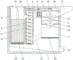
FIG. 1 is a schematic structural view of the present invention;
FIG. 2 is a schematic perspective view of the separator tank of the present invention;
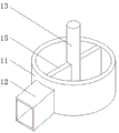
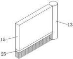
FIG. 3 is a perspective view of the dial plate of the present invention;
fig. 4 is a perspective view of the collecting barrel of the present invention.
In the drawings, the components represented by the respective reference numerals are listed below:
1. a box body; 2. mounting a plate; 3. a motor; 4. a driving wheel; 5. a delivery box; 6. a packing auger; 7. a first driven wheel; 8. a barrel body; 9. a collection barrel; 10. a crushing box; 11. a separation tank; 12. an inclined tube; 13. a rotating rod; 14. a crushing knife; 15. dialing a plate; 16. a second driven wheel; 17. a water inlet pipe; 18. a water outlet pipe; 19. a handle; 20. a first filter plate; 21. a second filter plate; 22. a sloping plate; 23. a baffle; 24. a flow guide pipe; 25. a brush; 26. and (7) a cover plate.
Detailed Description
The technical solutions in the embodiments of the present invention will be clearly and completely described below with reference to the drawings in the embodiments of the present invention, and it is obvious that the described embodiments are only a part of the embodiments of the present invention, and not all embodiments, and all other embodiments obtained by a person of ordinary skill in the art without any creative work based on the embodiments of the present invention belong to the protection scope of the present invention.
Example one
Referring to the drawings, the present invention provides a technical solution: a pollution discharge device for a production workshop comprises a box body 1, wherein a mounting plate 2 is welded at the top of an inner cavity of the box body 1, a motor 3 is fixedly mounted on the front surface of the mounting plate 2, a driving wheel 4 is fixedly mounted on an output shaft of the motor 3, a conveying box 5 is arranged on the left side of the mounting plate 2, an auger 6 is rotatably connected to the top of the inner cavity of the conveying box 5, a first driven wheel 7 is fixedly mounted at the upper end of the surface of the auger 6, the driving wheel 4 is in transmission connection with the first driven wheel 7 through a belt, a barrel body 8 is fixedly mounted on the left side of the inner cavity of the box body 1, an opening is formed in the upper end of the right side of the barrel body 8, the barrel body 8 is communicated with the conveying box 5 through the opening, and a collecting barrel 9 is placed in the inner cavity of the barrel body 8;
the crushing box 10 is fixedly installed at the upper end of the right side of the inner cavity of the box body 1, the separation box 11 is fixedly installed at the middle end of the right side of the inner cavity of the box body 1, the left side of the separation box 11 is communicated with an inclined tube 12, the left side of the inclined tube 12 is communicated with the conveying box 5, the top of the inner cavity of the box body 1 is rotatably connected with a rotating rod 13, the bottom of the rotating rod 13 penetrates through the crushing box 10 and extends to the outside of the crushing box, a crushing knife 14 is fixedly installed at the middle end of the surface of the rotating rod 13, the crushing knife 14 is located inside the crushing box 10, a shifting plate 15 is fixedly installed at the lower end of the surface of the rotating rod 13, the shifting plate 15 is located inside the separation box 11, a second driven wheel 16 is fixedly installed at the upper end of the surface of the rotating rod 13, and the second driven wheel 16 is in transmission connection with the driving wheel 4 through a belt;
the upper end of the right side of the box body 1 is communicated with a water inlet pipe 17, and the lower end of the right side of the box body 1 is communicated with a water outlet pipe 18.
Specifically, a handle 19 is fixedly mounted at the top of the collecting barrel 9, and holes are formed in the surface of the collecting barrel 9.
Specifically, the top and the bottom of the separation box 11 are both open, a first filter plate 20 is fixedly mounted at the bottom of the separation box 11, and the top of the first filter plate 20 is rotatably connected with the bottom of the rotating rod 13.
Specifically, the bottom of the barrel body 8 and the bottom of the conveying box 5 are both provided with a through groove, a second filter plate 21 is fixedly mounted on the inner wall of the through groove, and the bottom of the packing auger 6 is rotatably connected with the top of the second filter plate 21.
Specifically, the bottom of the inner cavity of the box body 1 is fixedly provided with an inclined plate 22, both sides of the bottom of the inner cavity of the crushing box 10 are fixedly provided with guide plates 23, and the bottom of the crushing box 10 is communicated with a guide pipe 24.
The working principle of the embodiment is as follows: the device is integrally buried under the bottom, the top of the box body 1 needs to be leveled with the ground, meanwhile, a water inlet pipe 17 needs to be communicated with a sewage discharge port in a workshop, when sewage containing solid impurities enters the crushing box 10 through the water inlet pipe 17, an output shaft of a motor 3 drives a driving wheel 4 to rotate, the driving wheel 4 drives a second driven wheel 16 to rotate through a belt, the second driven wheel 16 drives a rotating rod 13 to rotate, the rotating rod 13 drives a crushing cutter 14 to rotate to crush the solid impurities in the sewage, the crushed impurities and the sewage flow into the separation box 11 after a guide plate 23 and a guide pipe 24 are guided, as the bottom of the separation box 11 is provided with a first filter plate 20, the sewage can flow to the lower part of the box body 1 through the first filter plate 20, and the crushed solid impurities can be left on the first filter plate 20, and as a stirring plate 15 is arranged on the surface of the rotating rod 13, when the rotating rod 13 rotates, the stirring plate 15 can be driven to rotate, impurities on the first filter plate 20 are stirred to the inclined tube 12 by the stirring plate 15 and finally flow into the conveying box 5 through the inclined tube 12, and the first driven wheel 7 is connected with the driving wheel 4 through a belt, so that the driving wheel 4 can drive the first driven wheel 7 to rotate, the first driven wheel 7 drives the packing auger 6 to rotate, and the packing auger 6 conveys the impurities at the bottom of the conveying box 5 to enable the impurities to flow into the collecting barrel 9 from the through hole;
the device is also provided with a second filter plate 21, and the surface of the collecting barrel 9 is provided with holes, so that sewage attached to the surface of impurities can flow out of the box body 1, and accumulation and residue of sewage generated in the conveying box 5 and the collecting barrel 9 are avoided.
Example two
The structure of the present embodiment is basically the same as that of the first embodiment, except that the bottom of the shifting plate 15 is fixedly provided with the brush 25, the bottom of the brush 25 is in contact with the top of the first filter plate 20, and the surface of the first filter plate 20 can be washed when the shifting plate 15 rotates through the arrangement of the brush 25, so as to avoid the first filter plate 20 being blocked by impurities to affect solid-liquid separation.
EXAMPLE III
The structure of this embodiment is basically the same as that of the first embodiment, except that the top of the barrel body 8 is hinged with a cover plate 26, the top of the cover plate 26 is fixedly provided with a pull rod, and through the arrangement of the pull rod and the cover plate 26, when the impurities in the collecting barrel 9 are excessive, the cover plate 26 can be opened, the collecting barrel 9 can be taken out, and the impurities in the collecting barrel can be cleaned, so that the advantage of conveniently treating the impurities is achieved.
In the description herein, references to the description of "one embodiment," "an example," "a specific example" or the like are intended to mean that a particular feature, structure, material, or characteristic described in connection with the embodiment or example is included in at least one embodiment or example of the utility model. In this specification, the schematic representations of the terms used above do not necessarily refer to the same embodiment or example. Furthermore, the particular features, structures, materials, or characteristics described may be combined in any suitable manner in any one or more embodiments or examples.
The preferred embodiments of the utility model disclosed above are intended to be illustrative only. The preferred embodiments are not exhaustive and do not limit the utility model to the precise embodiments disclosed. Obviously, many modifications and variations are possible in light of the above teaching. The embodiments were chosen and described in order to best explain the principles of the utility model and the practical application, to thereby enable others skilled in the art to best utilize the utility model. The utility model is limited only by the claims and their full scope and equivalents.
Claims (7)
1. The utility model provides a waste fitting discharging in workshop, includes box (1), its characterized in that: the automatic feeding device is characterized in that a mounting plate (2) is welded at the top of an inner cavity of the box body (1), a motor (3) is fixedly mounted on the front side of the mounting plate (2), a driving wheel (4) is fixedly mounted on an output shaft of the motor (3), a conveying box (5) is arranged on the left side of the mounting plate (2), an auger (6) is rotatably connected to the top of the inner cavity of the conveying box (5), a first driven wheel (7) is fixedly mounted at the upper end of the surface of the auger (6), the driving wheel (4) is in transmission connection with the first driven wheel (7) through a belt, a barrel body (8) is fixedly mounted on the left side of the inner cavity of the box body (1), a through hole is formed in the upper end of the right side of the barrel body (8), the barrel body (8) is communicated with the conveying box (5) through the through hole, and a collecting barrel (9) is placed in the inner cavity of the barrel body (8);
a crushing box (10) is fixedly arranged at the upper end of the right side of the inner cavity of the box body (1), a separating box (11) is fixedly arranged at the middle end of the right side of the inner cavity of the box body (1), an inclined pipe (12) is communicated with the left side of the separation box (11), the left side of the inclined pipe (12) is communicated with the conveying box (5), the top of the inner cavity of the box body (1) is rotatably connected with a rotating rod (13), the bottom of the rotating rod (13) penetrates through the crushing box (10) and extends to the outside of the crushing box, the middle end of the surface of the rotating rod (13) is fixedly provided with a crushing knife (14), the crushing knife (14) is positioned inside the crushing box (10), the lower end of the surface of the rotating rod (13) is fixedly provided with a shifting plate (15), the shifting plate (15) is positioned in the separating box (11), a second driven wheel (16) is fixedly arranged at the upper end of the surface of the rotating rod (13), the second driven wheel (16) is in transmission connection with the driving wheel (4) through a belt;
the upper end on the right side of the box body (1) is communicated with a water inlet pipe (17), and the lower end on the right side of the box body (1) is communicated with a water outlet pipe (18).
2. The blow-down apparatus for a manufacturing plant according to claim 1, wherein: the top of the collecting barrel (9) is fixedly provided with a handle (19), and the surface of the collecting barrel (9) is provided with holes.
3. The blow-down apparatus for a manufacturing plant according to claim 1, wherein: the top and the bottom of separator box (11) are uncovered setting, the bottom fixed mounting of separator box (11) has first filter plate (20), the top of first filter plate (20) is rotated with the bottom of bull stick (13) and is connected.
4. The blow-down apparatus for a manufacturing plant according to claim 1, wherein: the bottom of staving (8) and delivery box (5) has all been seted up logical groove, and the inner wall fixed mounting who leads to the groove has second filter plate (21), the bottom of auger (6) is rotated with the top of second filter plate (21) and is connected.
5. The blow-down apparatus for a manufacturing plant according to claim 1, wherein: the bottom fixed mounting of box (1) inner chamber has swash plate (22), the equal fixed mounting in both sides of smashing case (10) inner chamber bottom has guide plate (23), the bottom intercommunication of smashing case (10) has honeycomb duct (24).
6. The blow-down apparatus for a manufacturing plant according to claim 3, wherein: the bottom of the poking plate (15) is fixedly provided with a brush (25), and the bottom of the brush (25) is in contact with the top of the first filter plate (20).
7. The blow-down apparatus for a manufacturing plant according to claim 1, wherein: the top of the barrel body (8) is hinged with a cover plate (26), and a pull rod is fixedly mounted at the top of the cover plate (26).
Priority Applications (1)
| Application Number | Priority Date | Filing Date | Title |
|---|---|---|---|
| CN202121456907.0U CN215627143U (en) | 2021-06-29 | 2021-06-29 | Sewage discharge device for production workshop |
Applications Claiming Priority (1)
| Application Number | Priority Date | Filing Date | Title |
|---|---|---|---|
| CN202121456907.0U CN215627143U (en) | 2021-06-29 | 2021-06-29 | Sewage discharge device for production workshop |
Publications (1)
| Publication Number | Publication Date |
|---|---|
| CN215627143U true CN215627143U (en) | 2022-01-25 |
Family
ID=79946410
Family Applications (1)
| Application Number | Title | Priority Date | Filing Date |
|---|---|---|---|
| CN202121456907.0U Expired - Fee Related CN215627143U (en) | 2021-06-29 | 2021-06-29 | Sewage discharge device for production workshop |
Country Status (1)
| Country | Link |
|---|---|
| CN (1) | CN215627143U (en) |
-
2021
- 2021-06-29 CN CN202121456907.0U patent/CN215627143U/en not_active Expired - Fee Related
Similar Documents
| Publication | Publication Date | Title |
|---|---|---|
| CN210754289U (en) | Pretreatment device for solid garbage landfill | |
| CN111744620A (en) | Garbage crushing treatment device for environmental protection | |
| CN113943053B (en) | Domestic sewage treatment device | |
| CN210545488U (en) | Waste battery crushing and sorting device | |
| CN117753761A (en) | Environment-friendly equipment for solid waste treatment | |
| CN219292371U (en) | Kitchen garbage innocent treatment equipment | |
| CN215627143U (en) | Sewage discharge device for production workshop | |
| CN217377514U (en) | A waste water drainage processing apparatus for green building | |
| CN111905887A (en) | Intelligent organic garbage treatment device and method | |
| CN216540142U (en) | Kitchen waste treatment equipment | |
| CN216946534U (en) | Filter device for construction water supply and drainage engineering | |
| CN216552157U (en) | City river sediment removal device for hydraulic engineering | |
| CN215253097U (en) | Hydraulic engineering desilting equipment | |
| CN214940835U (en) | A garbage collection device for municipal works drain | |
| CN211290732U (en) | Environment-friendly refuse treatment device for municipal works | |
| CN212237461U (en) | Garbage disposal equipment for construction to dust is handled | |
| CN211051646U (en) | Environment-friendly reducing mechanism that urban construction rubbish was recycled | |
| CN210266397U (en) | Hydraulic pipeline for hydraulic engineering | |
| CN220878016U (en) | Grid machine for sewage treatment | |
| CN221535897U (en) | Circulation processing apparatus of clean papermaking waste residue | |
| CN215232391U (en) | Energy-concerving and environment-protective type municipal administration sewage treatment device | |
| CN217887140U (en) | Sewage solid environment-friendly filtering device for garbage power plant | |
| CN211393907U (en) | Suspended matter removing device for sewage treatment | |
| CN221244159U (en) | A blow off pipeline for plant's blowdown | |
| CN216614227U (en) | Industrial sewage discharging and purifying equipment for ocean environmental protection |
Legal Events
| Date | Code | Title | Description |
|---|---|---|---|
| GR01 | Patent grant | ||
| GR01 | Patent grant | ||
| CF01 | Termination of patent right due to non-payment of annual fee |
Granted publication date: 20220125 |
|
| CF01 | Termination of patent right due to non-payment of annual fee |