Grid type radiator for transformer or reactor
Technical Field
The utility model relates to the technical field of radiators, in particular to a grid type radiator for a transformer or a reactor.
Background
The radiating fin is a device for radiating heat of electronic elements which are easy to generate heat in electrical appliances, and is made of aluminum alloy, brass or bronze into a plate shape, a sheet shape, a plurality of sheet shapes and the like, for example, a CPU (central processing unit) in a computer needs to use a relatively large radiating fin, and power tubes, row tubes and power amplifier tubes in a power amplifier in a television set need to use the radiating fin. Generally, a layer of heat-conducting silicone grease is coated on the contact surface of an electronic component and a heat sink when the heat sink is in use, so that heat emitted by the component is more effectively conducted to the heat sink and then dissipated to the ambient air through the heat sink.
The existing heat dissipation device in the transformer or the reactor mainly adopts air cooling, a plurality of ventilation openings are formed through gaps among coils, and then heat energy is blown away by a fan.
SUMMERY OF THE UTILITY MODEL
The utility model aims to solve the defects in the prior art, and provides a grid type radiator for a transformer or a reactor.
In order to achieve the purpose, the utility model adopts the following technical scheme:
the utility model provides a grid formula radiator for transformer or reactor, includes the frame, the connecting plate is all installed at the turning all around of frame inner wall, and the connecting plate keeps away from the one end of frame and installs the inside casing, the frame outer wall is provided with the cooler bin, and the one end that the cooler bin was kept away from to frame bottom outer wall passes through bolt fixedly connected with fixed plate, bolt fixedly connected with fan is passed through to the one end of fixed plate top outer wall.
Preferably, the inner wall of the cooling box is bonded with a sealing gasket, and the outer wall of one side of the sealing gasket is tightly attached to the outer wall of the outer frame.
Preferably, the inner side and the outer side of the outer frame are both connected with first heat dissipation strips distributed equidistantly, the outer walls of the two sides of the connecting plate are both connected with second heat dissipation strips distributed equidistantly, and the inner side and the outer side of the inner frame are both connected with third heat dissipation strips distributed equidistantly.
Preferably, the inner wall of the inner frame is provided with a main ventilation opening, and auxiliary ventilation openings which are symmetrically distributed are formed among the outer frame, the connecting plate and the inner frame.
Preferably, the outer wall of the top of the cooling box is provided with a liquid inlet, and the outer wall of the bottom of the cooling box is provided with a liquid outlet.
Preferably, the inner walls of the liquid inlet and the liquid outlet are respectively inserted with a plug, and the cooling box is filled with cooling liquid.
The utility model has the beneficial effects that:
1. according to the grid type radiator for the transformer or the reactor, the cooling box is arranged on the outer frame, the cooling liquid in the cooling box has large specific heat capacity, so that the temperature of the cooling box is difficult to rise while absorbing a large amount of heat, and cooling circulation is realized by matching with the heat dissipation of the fan;
2. according to the grid type radiator for the transformer or the reactor, the first radiating strips, the second radiating strips and the third radiating strips which are distributed equidistantly are arranged on the inner side and the outer side of the outer frame, the connecting plate and the inner frame respectively, so that the radiating area is increased, the heat conducting effect is good, and the radiating effect of the radiator is greatly improved.
Drawings
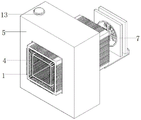
Fig. 1 is a front view of an overall structure of a grid type heat sink for a transformer or a reactor according to the present invention;
fig. 2 is a schematic structural view of a primary vent and a secondary vent of a grid type heat sink for a transformer or a reactor according to the present invention;
fig. 3 is a bottom view of the whole structure of a grid type heat sink for a transformer or a reactor according to the present invention.
In the figure: the air conditioner comprises an outer frame 1, a connecting plate 2, an inner frame 3, a sealing gasket 4, a cooling box 5, a fixing plate 6, a fan 7, a first heat dissipation strip 8, a second heat dissipation strip 9, a third heat dissipation strip 10, a main ventilation opening 11, an auxiliary ventilation opening 12, a liquid inlet 13, a liquid outlet 14 and a leather plug 15.
Detailed Description
The technical solutions in the embodiments of the present invention will be clearly and completely described below with reference to the drawings in the embodiments of the present invention, and it is obvious that the described embodiments are only a part of the embodiments of the present invention, and not all of the embodiments.
Referring to fig. 1-3, a grid type radiator for a transformer or a reactor comprises an outer frame 1, wherein connecting plates 2 are mounted at the corners of the periphery of the inner wall of the outer frame 1, an inner frame 3 is mounted at one end, away from the outer frame 1, of each connecting plate 2, a cooling box 5 is arranged on the outer wall of the outer frame 1, one end, away from the cooling box 5, of the outer wall of the bottom of the outer frame 1 is fixedly connected with a fixing plate 6 through bolts, a sealing gasket 4 is bonded on the inner wall of the cooling box 5, the outer wall of one side of the sealing gasket 4 is tightly attached to the outer wall of the outer frame 1, one end, at the top of the outer wall of the fixing plate 6, of a fan 7 is fixedly connected through bolts, the cooling box 5 is mounted on the outer frame 1, and as the specific heat capacity of cooling liquid in the cooling box 5 is large, the temperature of the cooling liquid is difficult to rise while a large amount of heat is absorbed, and the cooling liquid is matched with the heat dissipation of the fan 7, so that the cooling circulation is realized;
the inner side and the outer side of the outer frame 1 are both connected with first heat dissipation strips 8 which are distributed equidistantly, the outer walls of the two sides of the connecting plate 2 are both connected with second heat dissipation strips 9 which are distributed equidistantly, the inner side and the outer side of the inner frame 3 are both connected with third heat dissipation strips 10 which are distributed equidistantly, and the first heat dissipation strips 8, the second heat dissipation strips 9 and the third heat dissipation strips 10 which are distributed equidistantly are respectively arranged on the inner side and the outer side of the outer frame 1, the connecting plate 2 and the inner frame 3, so that the heat dissipation area is increased, the heat conduction effect is good, and the heat dissipation effect of the radiator is greatly improved;
the inner wall of the inner frame 3 is provided with a main vent 11, auxiliary vents 12 which are symmetrically distributed are formed among the outer frame 1, the connecting plate 2 and the inner frame 3, a liquid inlet 13 is formed in the outer wall of the top of the cooling box 5, a liquid outlet 14 is formed in the outer wall of the bottom of the cooling box 5, leather plugs 15 are inserted into the inner walls of the liquid inlet 13 and the liquid outlet 14, and cooling liquid is filled in the cooling box 5.
The working principle is as follows: heat energy generated by the transformer or the reactor during working can be blown into the main ventilation opening 11 and the auxiliary ventilation opening 12 by the fan 7, the connecting plates 2 are arranged at four corners of the inner wall of the outer frame 1, the inner frame 3 is arranged at one end of the connecting plates 2, the first heat dissipation strips 8, the second heat dissipation strips 9 and the third heat dissipation strips 10 which are distributed equidistantly are respectively arranged on the inner side and the outer side of the outer frame 1, the connecting plates 2 and the inner frame 3, the heat dissipation area is large, one part of the heat energy is blown away by the fan 7, and the other part of the heat energy is absorbed by cooling liquid in the cooling box 5, so that the heat dissipation of the transformer or the reactor is realized.
In the description of the present invention, it is to be understood that the terms "center", "longitudinal", "lateral", "length", "width", "thickness", "upper", "lower", "front", "rear", "left", "right", "vertical", "horizontal", "top", "bottom", "inner", "outer", "clockwise", "counterclockwise", and the like, indicate orientations and positional relationships based on those shown in the drawings, and are used only for convenience of description and simplicity of description, and do not indicate or imply that the equipment or element being referred to must have a particular orientation, be constructed and operated in a particular orientation, and thus, should not be considered as limiting the present invention.
Furthermore, the terms "first", "second" and "first" are used for descriptive purposes only and are not to be construed as indicating or implying relative importance or implicitly indicating the number of technical features indicated. Thus, a feature defined as "first" or "second" may explicitly or implicitly include one or more of that feature. In the description of the present invention, "a plurality" means two or more unless specifically defined otherwise.
The above description is only for the preferred embodiment of the present invention, but the scope of the present invention is not limited thereto, and any person skilled in the art should be considered to be within the technical scope of the present invention, and equivalent alternatives or modifications according to the technical solution of the present invention and the inventive concept thereof should be covered by the scope of the present invention.