CN215509047U - Bench drill that practicality is strong - Google Patents
Bench drill that practicality is strong Download PDFInfo
- Publication number
- CN215509047U CN215509047U CN202122087780.6U CN202122087780U CN215509047U CN 215509047 U CN215509047 U CN 215509047U CN 202122087780 U CN202122087780 U CN 202122087780U CN 215509047 U CN215509047 U CN 215509047U
- Authority
- CN
- China
- Prior art keywords
- wall
- rod
- rigid coupling
- shaped plate
- motor
- Prior art date
- Legal status (The legal status is an assumption and is not a legal conclusion. Google has not performed a legal analysis and makes no representation as to the accuracy of the status listed.)
- Active
Links
Images

Abstract
The utility model discloses a bench drill with strong practicability, which comprises a shell, wherein a lifting mechanism is arranged in an inner cavity of the shell, the lifting mechanism comprises a second motor, a first screw rod, a threaded sleeve, a sliding block, a groove body, an L-shaped rod and a T-shaped plate, one end of the L-shaped rod is fixedly connected with the T-shaped plate, and the interior of the T-shaped plate is rotatably connected above the outer wall of a cylinder body through a bearing. This bench drill that practicality is strong, through the second motor, first screw rod, a thread section of thick bamboo, the slider, the cell body, L shape pole, cooperation between T shaped plate and the slide rail, make the device when using, it is spacing to slide through T shaped plate and slide rail constitution, make the slip of thread bush accessible cell body and L shape pole link to each other and drive the stable reciprocating of barrel, and then make the barrel can drive the drill bit and at the uniform velocity drill, the mode drilling that the main shaft relies on manual feed has been solved, manual mode feed rate is inhomogeneous, the problem that the drill bit is broken easily.
Description
Technical Field
The utility model relates to the technical field of bench drilling machines, in particular to a bench drill with strong practicability.
Background
A bench drilling machine is a bench drill for short, and refers to a small-sized drilling machine which can be placed on an operation table and is provided with a main shaft in vertical arrangement. The diameter of the bench drill is generally less than 13 mm, and generally not more than 25 mm. The main shaft speed change is generally realized by changing the position of a triangular belt on a tower-shaped belt wheel, and the main shaft feeding is manually operated.
When the existing bench drill is used, a spindle drills holes in a manual feeding mode, the feeding speed of the manual mode is uneven, a drill bit is easily broken, workpieces are mostly required to be extruded and fixed by one hand, the fixing mode is relatively unstable, and the hands can be damaged.
Disclosure of Invention
The utility model aims to provide a bench drill with strong practicability, which aims to solve the problems that the spindle provided by the background technology drills in a manual feeding mode, the feeding speed of the manual feeding mode is uneven, and a drill bit is easy to break.
In order to achieve the purpose, the utility model provides the following technical scheme: a bench drill with strong practicability comprises a shell, wherein a first motor is installed on one side of the top of the shell, the output end of the first motor is connected to the top of the shell in a rotating mode through a bearing, a barrel is in clearance fit with the outer wall of the output end of the first motor, the outer wall of the barrel is in clearance fit with the inner wall of a through hole of the shell, a drill bit is installed at the bottom of the barrel, and a lifting mechanism is arranged in an inner cavity of the shell;
the lifting mechanism comprises a second motor, a first screw rod, a threaded sleeve, a sliding block, a groove body, an L-shaped rod and a T-shaped plate;
the utility model discloses a screw thread sleeve, including casing, second motor, output end rigid coupling, slider, slide link to each other in the spout inner wall of casing inner chamber one side, the outer wall opposite side rigid coupling of thread sleeve has the cell body, the inner wall of cell body slides and links to each other has L shape pole, the one end rigid coupling of L shape pole has the T-shaped plate, the inside of T-shaped plate rotates through the bearing and links to each other in the outer wall top of barrel.
Preferably, a slide rail is fixedly connected to one side of the inner cavity of the housing, and the inner wall of the slide rail is connected to one side of the T-shaped plate in a sliding manner.
Preferably, the bottom of casing is rigid coupling has the stand, the bottom rigid coupling of stand has the base.
Preferably, one side of the upright post is provided with a fixing mechanism;
the fixing mechanism comprises a box body, a second screw rod, a block body and a clamping rod;
the box is installed in one side of stand, the inner chamber both sides of box all rotate through the bearing and link to each other and have the second screw rod, two the outer wall of second screw rod all the screw thread links to each other has the block, two outer wall one side of block slides respectively and links to each other in the spout inner wall of bottom half both sides, two the equal rigid coupling of outer wall opposite side of block has the clamping bar, two the outer wall of clamping bar slides respectively and links to each other in the logical groove inner wall of box top both sides.
Preferably, the inner cavity of the box body is provided with a transmission mechanism;
the transmission mechanism comprises a rod body, a handle, a driving wheel and a driven wheel;
the body of rod passes through the bearing and rotates the bottom that links to each other in the box, the one end rigid coupling of the body of rod has the handle, the other end rigid coupling of the body of rod has the action wheel, the both sides of action wheel all mesh and link to each other have from the driving wheel, two from one side of driving wheel rigid coupling respectively in the one end of two second screw rods.
Compared with the prior art, the utility model has the beneficial effects that: the utility model has scientific and reasonable structure and safe and convenient use.
This bench drill that practicality is strong, through the second motor, first screw rod, a thread section of thick bamboo, the slider, the cell body, L shape pole, cooperation between T shaped plate and the slide rail, make the device when using, the second motor can drive first screw rod and rotate, it is continuous to slide through slider and casing inner chamber one side spout, make the rotation of first screw rod can drive the stable removal of thread bush and control, it is spacing to slide through T shaped plate and slide rail constitution, make the slip of thread bush accessible cell body and L shape pole link to each other and drive the stable reciprocating of barrel, and then make the barrel can drive the drill bit at the uniform velocity drilling, the mode drilling that the main shaft relies on manual feed has been solved, manual mode feed speed is inhomogeneous, the problem that the drill bit breaks easily.
Through the second screw rod, cooperation between block and the clamping bar, make the device when using, slip through block and bottom half spout links to each other, make the rotation in opposite directions of two second screw rods can drive two blocks simultaneously and stabilize about the removal in opposite directions, it links to each other to lead to the slip of groove through two clamping bars and box top both sides, make two clamping bars can be fixed the top centre gripping of work piece at the box, it needs the singlehanded extrusion fixed to have solved the work piece mostly, this kind of fixed mode is unstable relatively, can cause the problem of injury to the hand.
Through the body of rod, handle, action wheel and the cooperation from between the driving wheel for the device is when using, and the handle can drive the body of rod and rotate, and is continuous through action wheel and two meshing from between the driving wheel, makes the rotation of the body of rod can drive two second screw rods simultaneously and rotate in opposite directions, and then has made two clamping bars can be with the stable centre gripping of work piece, has made things convenient for user's operation.
Drawings
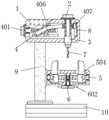
FIG. 1 is a schematic diagram of the connection relationship of the present invention;
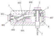
FIG. 2 is a schematic cross-sectional view of the housing, the first motor, and the base of FIG. 1;
FIG. 3 is a schematic structural view of the L-shaped bar, the slide rail and the T-shaped plate of FIG. 2;
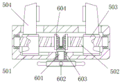
fig. 4 is a schematic view of the structure of the clamping bar and the handle in fig. 2.
In the figure: 1. the device comprises a shell, 2, a first motor, 3, a barrel, 4, a lifting mechanism, 401, a second motor, 402, a first screw rod, 403, a threaded sleeve, 404, a sliding block, 405, a groove body, 406, an L-shaped rod, 407, a T-shaped plate, 5, a fixing mechanism, 501, a box body, 502, a second screw rod, 503, a block body, 504, a clamping rod, 6, a transmission mechanism, 601, a rod body, 602, a handle, 603, a driving wheel, 604, a driven wheel, 7, a drill bit, 8, a sliding rail, 9, an upright post, 10 and a base.
Detailed Description
The technical solutions in the embodiments of the present invention will be clearly and completely described below with reference to the drawings in the embodiments of the present invention, and it is obvious that the described embodiments are only a part of the embodiments of the present invention, and not all of the embodiments. All other embodiments, which can be derived by a person skilled in the art from the embodiments given herein without making any creative effort, shall fall within the protection scope of the present invention.
Referring to fig. 1-4, the present invention provides a technical solution: a bench drill with strong practicability comprises a shell 1, wherein a first motor 2 is installed on one side of the top of the shell 1, a user can select the type of the first motor 2 according to actual requirements, the output end of the first motor 2 is connected to the top of the shell 1 through a bearing in a rotating mode, the rotating stability of the first motor 2 is improved, a barrel 3 is in clearance fit with the outer wall of the output end of the first motor 2, the clearance fit position of the outer wall of the output end of the first motor 2 and the inner wall of the barrel 3 is rectangular, the outer wall of the barrel 3 is in clearance fit with the inner wall of a through hole of the shell 1, a drill bit 7 is installed at the bottom of the barrel 3, the barrel 3 can drive the drill bit 7 to drill downwards, a lifting mechanism 4 is arranged in an inner cavity of the shell 1, the lifting mechanism 4 comprises a second motor 401, a first screw 402, a threaded sleeve 403, a sliding block 404, a groove body 405, an L-shaped rod 406 and a T-shaped plate 407, the second motor 401 is installed on the left side of the shell 1, the user can select the model of the second motor 401 according to the actual requirement, the output end of the second motor 401 is fixedly connected with the first screw 402, so that the second motor 401 can drive the first screw 402 to rotate, one side of the outer wall of the first screw 402 is connected with one side of the inner cavity of the shell 1 through the rotation of the bearing, the rotation stability of the first screw 401 is increased, the outer wall thread of the first screw 402 is connected with the threaded sleeve 403, one side of the outer wall of the threaded sleeve 403 is fixedly connected with the sliding block 404, the sliding block 404 is connected with the inner wall of the sliding groove at one side of the inner cavity of the shell 1 in a sliding way, so that the rotation of the first screw 402 can drive the threaded sleeve 403 to move left and right stably, the other side of the outer wall of the threaded sleeve is fixedly connected with the groove body 405, so that the threaded sleeve 403 can drive the groove body 405 to move left and right, the inner wall of the groove body 405 is connected with the L-shaped rod 406 in a sliding way, one end of the L-shaped rod 403 is fixedly connected with the T-shaped plate 407, make the accessible and the slip of L shape pole 406 link to each other and drive T shaped plate 407 about cell body 405 reciprocate, the inside of T shaped plate 407 rotates through the bearing and links to each other in the outer wall top of barrel 3, make T shaped plate 407 can drive pivoted barrel 3 and reciprocate, inner chamber one side rigid coupling of casing 1 has slide rail 8, the inner wall of slide rail 8 slides and links to each other in one side of T shaped plate 407, it is spacing to slide through T shaped plate 407 and slide rail 8 constitution, make the removal of barrel 3 have stability, casing 1's bottom rigid coupling has stand 9, stand 9's bottom rigid coupling has base 10, make stand 9 and base 10 can play the supporting role to casing 1.
One side of stand 9 is equipped with fixed establishment 5, fixed establishment 5 includes box 501, second screw 502, block 503 and clamping bar 504, box 501 installs in one side of stand 9, box 501's inner chamber both sides all rotate through the bearing and link to each other and have connected second screw 502, the screw thread direction of two second screws 502 is the same, the equal screw thread of outer wall of two second screws 502 links to each other block 503, make the opposite rotation accessible of two second screws 502 drive two blocks 503 and control the relative movement, outer wall one side of two blocks 503 slides respectively and links to each other in the spout inner wall of box 501 bottom both sides, slide through block 503 and box 501 bottom spout and link to each other, make the removal of block 503 have stability, the equal rigid coupling of outer wall opposite side of two blocks 503 has clamping bar 504, the outer wall of two clamping bar 504 slides respectively and links to each other in the logical inslot wall of box 501 top both sides, make the left and right sides relative movement of two blocks 503 can drive two clamping bar 504 and clamp the work piece fixedly at the top of box 501.
The inner chamber of box 501 is equipped with drive mechanism 6, drive mechanism 6 includes the body of rod 601, handle 602, action wheel 603 and follow driving wheel 604, the body of rod 601 passes through the bearing and rotates and links to each other in the bottom of box 501, the one end rigid coupling of the body of rod 601 has handle 602, make handle 602 can drive body of rod 601 and rotate, the other end rigid coupling of the body of rod 601 has action wheel 603, make body of rod 601 can drive action wheel 603 and rotate, the both sides of action wheel 603 all mesh and link to each other from driving wheel 604, two are followed one side of driving wheel 604 rigid coupling respectively in the one end of two second screw rods 502, it is continuous through the meshing between action wheel 603 and two follow driving wheels 604, make the rotation of the body of rod 601 drive two second screw rods 502 and rotate in opposite directions simultaneously.
When using this bench drill that the practicality is strong, second motor 401 can drive first screw rod 402 and rotate, it links to each other to slide through slider 404 and 1 inner chamber one side spout, make the rotation of first screw rod 402 can drive the stable removal about of thread bush 403, it is spacing to slide through T-shaped plate 407 and slide rail 8 constitution, make the slip of thread bush 403 accessible cell body 405 and L shape pole 406 link to each other and drive the steady reciprocating of barrel 3, and then make barrel 3 can drive drilling bit 7 at the uniform velocity drilling, the mode drilling that the main shaft relies on manual feed has been solved, manual mode feed rate is inhomogeneous, the problem that drill bit 7 is broken easily. Handle 602 can drive body of rod 601 and rotate, it is continuous with two meshing of following between the driving wheel 603 and the follow driving wheel 604, make the rotation of body of rod 601 drive two second screws 502 simultaneously and rotate in opposite directions, it links to each other to slide through block 503 and box 501 bottom spout, make the rotation in opposite directions of two second screws 502 can drive two blocks 503 stable controls in opposite directions simultaneously and remove, it links to each other to pass through the slip of two clamping bar 504 and box 501 top both sides logical groove, make two clamping bar 504 can be fixed the top centre gripping of work piece at box 501, it needs the one-hand extrusion to fix mostly to have solved the work piece, this kind of fixed mode is unstable relatively, may cause the problem of injury to the hand.
In the description of the present invention, it is to be understood that the terms "coaxial", "bottom", "one end", "top", "middle", "other end", "upper", "one side", "top", "inner", "front", "center", "both ends", and the like, indicate orientations or positional relationships based on those shown in the drawings, and are only for convenience of description and simplicity of description, and do not indicate or imply that the referenced device or element must have a particular orientation, be constructed and operated in a particular orientation, and thus, are not to be construed as limiting the present invention.
In the present invention, unless otherwise expressly specified or limited, the terms "mounted," "disposed," "connected," "secured," "screwed" and the like are to be construed broadly, e.g., as meaning fixedly connected, detachably connected, or integrally formed; can be mechanically or electrically connected; the terms may be directly connected or indirectly connected through an intermediate, and may be communication between two elements or interaction relationship between two elements, unless otherwise specifically limited, and the specific meaning of the terms in the present invention will be understood by those skilled in the art according to specific situations.
Although embodiments of the present invention have been shown and described, it will be appreciated by those skilled in the art that changes, modifications, substitutions and alterations can be made in these embodiments without departing from the principles and spirit of the utility model, the scope of which is defined in the appended claims and their equivalents.
Claims (5)
1. The utility model provides a bench drill that practicality is strong, includes casing (1), its characterized in that: a first motor (2) is installed on one side of the top of the shell (1), the output end of the first motor (2) is rotatably connected to the top of the shell (1) through a bearing, a barrel (3) is in clearance fit with the outer wall of the output end of the first motor (2), the outer wall of the barrel (3) is in clearance fit with the inner wall of a through hole of the shell (1), a drill bit (7) is installed at the bottom of the barrel (3), and a lifting mechanism (4) is arranged in an inner cavity of the shell (1);
the lifting mechanism (4) comprises a second motor (401), a first screw (402), a threaded sleeve (403), a sliding block (404), a groove body (405), an L-shaped rod (406) and a T-shaped plate (407);
second motor (401) is installed in the left side of casing (1), the output rigid coupling of second motor (401) has first screw rod (402), outer wall one side of first screw rod (402) is rotated through the bearing and is linked to inner chamber one side in casing (1), the outer wall screw thread of first screw rod (402) links to each other threaded sleeve (403), outer wall one side rigid coupling of threaded sleeve (403) has slider (404), slider (404) slide and link to each other in the spout inner wall of casing (1) inner chamber one side, the outer wall opposite side rigid coupling of threaded sleeve (403) has cell body (405), the inner wall of cell body (405) slides and links to each other L shape pole (406), the one end rigid coupling of L shape pole (406) has T shaped plate (407), the inside of T shaped plate (407) is rotated in the outer wall top of barrel (3) through the bearing.
2. A bench drill of high practicability as claimed in claim 1, wherein: a sliding rail (8) is fixedly connected to one side of the inner cavity of the shell (1), and the inner wall of the sliding rail (8) is connected to one side of the T-shaped plate (407) in a sliding mode.
3. A bench drill of high practicability as claimed in claim 1, wherein: the bottom rigid coupling of casing (1) has stand (9), the bottom rigid coupling of stand (9) has base (10).
4. A bench drill of high practicability as claimed in claim 3, wherein: one side of the upright post (9) is provided with a fixing mechanism (5);
the fixing mechanism (5) comprises a box body (501), a second screw (502), a block body (503) and a clamping rod (504);
box (501) are installed in one side of stand (9), the inner chamber both sides of box (501) are all rotated through the bearing and are linked to each other and have second screw rod (502), two the outer wall of second screw rod (502) all links to each other block (503), two outer wall one side of block (503) slides respectively and links to each other in the spout inner wall of box (501) bottom both sides, two the equal rigid coupling of outer wall opposite side of block (503) has clamping bar (504), two the outer wall of clamping bar (504) slides respectively and links to each other in the logical inslot inner wall of box (501) top both sides.
5. A bench drill of high practicability according to claim 4, characterized in that: the inner cavity of the box body (501) is provided with a transmission mechanism (6);
the transmission mechanism (6) comprises a rod body (601), a handle (602), a driving wheel (603) and a driven wheel (604);
the body of rod (601) passes through the bearing and rotates the bottom that links to each other in box (501), the one end rigid coupling of the body of rod (601) has handle (602), the other end rigid coupling of the body of rod (601) has action wheel (603), the both sides of action wheel (603) all mesh and link to each other from driving wheel (604), two from one side of driving wheel (604) rigid coupling in the one end of two second screw rods (502) respectively.
Priority Applications (1)
| Application Number | Priority Date | Filing Date | Title |
|---|---|---|---|
| CN202122087780.6U CN215509047U (en) | 2021-09-01 | 2021-09-01 | Bench drill that practicality is strong |
Applications Claiming Priority (1)
| Application Number | Priority Date | Filing Date | Title |
|---|---|---|---|
| CN202122087780.6U CN215509047U (en) | 2021-09-01 | 2021-09-01 | Bench drill that practicality is strong |
Publications (1)
| Publication Number | Publication Date |
|---|---|
| CN215509047U true CN215509047U (en) | 2022-01-14 |
Family
ID=79794854
Family Applications (1)
| Application Number | Title | Priority Date | Filing Date |
|---|---|---|---|
| CN202122087780.6U Active CN215509047U (en) | 2021-09-01 | 2021-09-01 | Bench drill that practicality is strong |
Country Status (1)
| Country | Link |
|---|---|
| CN (1) | CN215509047U (en) |
-
2021
- 2021-09-01 CN CN202122087780.6U patent/CN215509047U/en active Active
Similar Documents
| Publication | Publication Date | Title |
|---|---|---|
| CN215509047U (en) | Bench drill that practicality is strong | |
| CN212264574U (en) | Novel upright drill with adjustable rotation angle | |
| CN219464676U (en) | Feeding mechanism of cold header | |
| CN215658302U (en) | Clamping mechanism for slow-speed wire cutting machine | |
| CN214974341U (en) | Crushing system with waste pretreatment device | |
| CN213516108U (en) | Pressure sensor with good stability | |
| CN215919757U (en) | Radial drill with automatic clamping and fixing device | |
| CN114433900A (en) | Photovoltaic module metal fitting processing equipment | |
| CN215432859U (en) | Surface grinding machine with high stable structure | |
| CN215316400U (en) | Efficient integration laser cutting machine | |
| CN112815714A (en) | High metalworking smelting tool of stability | |
| CN220311858U (en) | Feed device for boring of horizontal lathe | |
| CN212822803U (en) | Fixing device is used in processing of automobile lower swing arm | |
| CN219724752U (en) | Steel pipe beveling equipment | |
| CN219817870U (en) | Reinforcing bar cutting jig for building | |
| CN215617623U (en) | Novel pneumatic reference chuck component | |
| CN218080473U (en) | Hardware machining drilling machine with cleaning mechanism | |
| CN215148993U (en) | Pipe fitting rack for building engineering | |
| CN214815284U (en) | Electric power construction is with outer protective tube cutting device | |
| CN215698728U (en) | Gas shielded welding machine capable of quickly adjusting air pressure | |
| CN220388058U (en) | Pipe cutter for hydropower installation | |
| CN220463690U (en) | DC brushless motor controller assembling structure | |
| CN214263728U (en) | Be used for bolt production to use high strength thread rolling device | |
| CN216178335U (en) | Drilling and hole grinding integrated numerical control machine tool cutter | |
| CN214054320U (en) | Three-axis positioning screw locking machine |
Legal Events
| Date | Code | Title | Description |
|---|---|---|---|
| GR01 | Patent grant | ||
| GR01 | Patent grant |