CN215504716U - Nephrology department hemodialysis device - Google Patents
Nephrology department hemodialysis device Download PDFInfo
- Publication number
- CN215504716U CN215504716U CN202122125616.XU CN202122125616U CN215504716U CN 215504716 U CN215504716 U CN 215504716U CN 202122125616 U CN202122125616 U CN 202122125616U CN 215504716 U CN215504716 U CN 215504716U
- Authority
- CN
- China
- Prior art keywords
- pipe
- fixedly arranged
- blood
- way pipe
- dialyzer
- Prior art date
- Legal status (The legal status is an assumption and is not a legal conclusion. Google has not performed a legal analysis and makes no representation as to the accuracy of the status listed.)
- Active
Links
Images


Abstract
The utility model discloses a hemodialysis device for nephrology department, and particularly relates to the technical field of hemodialysis devices. The blood filter is cleaned without stopping the whole device and the treatment efficiency is improved by opening the one-way valves on the first three-way pipe and the second three-way pipe at the same time and using the two thrombus filters to filter the blood, so that the dialysis effect on the blood is accelerated.
Description
Technical Field
The utility model relates to the technical field of hemodialysis devices, in particular to a hemodialysis device for nephrology department.
Background
At present, as people's living habits become more and more irregular, various symptoms can appear in the health, wherein the symptoms of acute and chronic renal failure become more and more, and can cause a series of clinical symptoms and metabolic disorders such as biochemistry, endocrine and the like, when treating patients with acute and chronic renal failure, a hemodialysis method is generally adopted, which is characterized in that the blood in the body is drained to the outside of the body, and the blood and dialysate with similar body concentration are arranged inside and outside one hollow fiber in a dialyzer consisting of a plurality of hollow fibers, and the substances are exchanged by the principles of dispersion, ultrafiltration, adsorption and convection, so that metabolic wastes in the body are removed, electrolyte and acid-base balance are maintained, excessive water in the body is removed, and the whole process of purified blood transfusion is called hemodialysis.
When the existing renal hemodialysis device is used, the thrombus filter is firstly required to be used for filtering blood so as to prevent thrombus particles in the blood from causing blockage of a pipeline, and after the renal hemodialysis device is used for a long time, more thrombus particles in the thrombus filter easily cause blockage of the thrombus filter, so that the flow speed of the blood can be reduced, and the dialysis effect is influenced.
SUMMERY OF THE UTILITY MODEL
In order to overcome the above-mentioned drawbacks of the prior art, embodiments of the present invention provide a hemodialysis apparatus for nephrology department, which solves the above-mentioned problems of the background art.
In order to achieve the purpose, the utility model provides the following technical scheme: the utility model provides a nephrology dept hemodialysis device, includes the cerini dialyser cerini, the fixed connecting pipe that is equipped with in cerini dialyser cerini top, the fixed blood return pipe that is equipped with in cerini dialyser cerini bottom, the fixed suction pump that is equipped with in connecting pipe one side, the suction pump delivery port is linked together with the connecting pipe, the fixed first three-way pipe that is equipped with in suction pump water inlet department, first three-way pipe bottom is equipped with two thrombus filters, and two thrombus filter bottoms are equipped with the second three-way pipe, the fixed blood vessel that takes off that is equipped with in second three-way pipe bottom, thrombus filter top and bottom are all fixed and are equipped with the conveyer pipe, conveyer pipe outer wall, first three-way pipe and second three-way pipe port department all fix and are equipped with the ring flange, set up threaded hole on the ring flange, screw hole female connection has the screw, through screw thread connection between two adjacent ring flanges.
In a preferred embodiment, the outer walls of the two ends of the first tee pipe and the second tee pipe are respectively and fixedly provided with a one-way valve.
In a preferred embodiment, the connecting pipe and the outer wall of the blood return pipe are both fixedly provided with a regulating valve and a pressure gauge, and the regulating valve is arranged on one side of the pressure gauge.
In a preferred embodiment, a dosing pipe is fixedly arranged on the outer wall of the top of the first three-way pipe, and a sealing plug is connected to the top of the dosing pipe in a threaded manner.
In a preferred embodiment, a silicone rubber heating belt is fixedly sleeved on one side of the outer wall of the blood return pipe, which is far away from the regulating valve.
In a preferred embodiment, a hose is fixedly arranged at the top of the outer wall at one side of the dialyzer, a liquid storage tank is fixedly arranged at one side of the hose, and a liquid feeding pipe is fixedly arranged at the top of the liquid storage tank.
In a preferred embodiment, a slag discharge pipe is fixedly arranged at the bottom of the outer wall at one side of the dialyzer.
The utility model has the technical effects and advantages that:
1. the blood filter is cleaned without stopping the whole device and the treatment efficiency is improved by opening the one-way valves on the first three-way pipe and the second three-way pipe at the same time and using the two thrombus filters to filter the blood, so that the dialysis effect on the blood is accelerated.
2. The silicone rubber heating belt is arranged on the blood returning pipe, the silicone rubber heating belt has elasticity, buffer protection can be formed on the outer wall of the blood returning pipe, the insulation performance and the voltage resistance of the silicone rubber heating belt are better than those of other heating belts, and the silicone rubber heating belt is safer to use.
Drawings
Fig. 1 is a front view of the overall structure of the present invention.
FIG. 2 is a front view of the thrombus filter of the present invention.
Fig. 3 is a side view of the overall structure of the present invention.
Fig. 4 is a cross-sectional view of a dosing tube of the present invention.
Fig. 5 is a cross-sectional view of a reservoir of the present invention.
The reference signs are: 1. a dialyzer; 2. a connecting pipe; 3. returning blood vessels; 4. a suction pump; 5. a first three-way pipe; 6. a thrombus filter; 7. a second three-way pipe; 8. removing blood vessels; 9. a delivery pipe; 10. a flange plate; 11. a threaded hole; 12. a screw; 13. a one-way valve; 14. adjusting a valve; 15. a pressure gauge; 16. a medicine feeding pipe; 17. a sealing plug; 18. a silicone rubber heating belt; 19. a hose; 20. a liquid storage tank; 21. a liquid feeding pipe; 22. a slag discharge pipe.
Detailed Description
The technical solutions in the embodiments of the present invention will be clearly and completely described below with reference to the drawings in the embodiments of the present invention, and it is obvious that the described embodiments are only a part of the embodiments of the present invention, and not all of the embodiments. All other embodiments, which can be derived by a person skilled in the art from the embodiments given herein without making any creative effort, shall fall within the protection scope of the present invention.
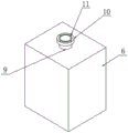
Referring to the attached drawings 1-5 in the specification, the hemodialysis device for nephrology department of the embodiment comprises a dialyzer 1, wherein a connecting pipe 2 is fixedly arranged at the top of the dialyzer 1, a blood return pipe 3 is fixedly arranged at the bottom of the dialyzer 1, a suction pump 4 is fixedly arranged on one side of the connecting pipe 2, the blood is sucked by the suction pump 4 and flows into a patient through the blood return pipe 3 after being dialyzed by the dialyzer 1, a water outlet of the suction pump 4 is communicated with the connecting pipe 2, a first three-way pipe 5 is fixedly arranged at a water inlet of the suction pump 4, two thrombus filters 6 are arranged at the bottom of the first three-way pipe 5, a second three-way pipe 7 is arranged at the bottoms of the two thrombus filters 6, the blood can be filtered simultaneously through the arrangement of the two thrombus filters 6, and the blood can also be treated by using one of the thrombus filters 6, when using one of them thrombus filter 6 to handle, can dismantle another thrombus filter 6, clear up the thrombus granule that the inside was filtered, prevent that the too much filter effect that influences thrombus filter 6 of thrombus granule, need not stop whole device, can last the processing to blood, improve the treatment effeciency, the fixed blood vessel 8 that takes off that is equipped with in second three-way pipe 7 bottom, 6 tops of thrombus filter and bottom all are fixed and are equipped with conveyer pipe 9, conveyer pipe 9 outer wall, first three-way pipe 5 and second three-way pipe 7 port department all are fixed and are equipped with ring flange 10, threaded hole 11 has been seted up on the ring flange 10, 11 threaded connection in threaded hole have screw 12, through screw 12 threaded connection between two adjacent ring flanges 10, conveniently dismantle thrombus filter 6 and clear up.
And the outer walls of the two ends of the first three-way pipe 5 and the second three-way pipe 7 are respectively fixedly provided with a one-way valve 13 for controlling the circulation of blood.
Connecting pipe 2 and return all fixed governing valve 14 and the manometer 15 of being equipped with on the 3 outer walls of blood vessel, governing valve 14 is established in manometer 15 one side, and medical personnel can look over the numerical value on the manometer 15, adjusts the flow rate of blood through governing valve 14.
A medicine feeding pipe 16 is fixedly arranged on the outer wall of the top of the first three-way pipe 5, and the top of the medicine feeding pipe 16 is in threaded connection with a sealing plug 17 for feeding other needed medicines.
The implementation scenario is specifically as follows: when in use, the blood removal pipe 8 at the bottom of the second three-way pipe 7 is connected with a medical vein needle, the vein needle is pricked into a vein of a patient, then the blood return pipe 3 is connected with a medical artery needle, the artery needle is pricked into an artery of the patient, the suction pump 4 is started to suck blood in the patient, the blood is firstly conveyed into the two thrombus filters 6 through the second three-way pipe 7, thrombus particles in the blood are filtered through the thrombus filters 6 to prevent the thrombus particles from blocking the connecting pipe 2 and influencing dialysis treatment, the blood flows into the suction pump 4 through the first three-way pipe 5 after being filtered by the two thrombus filters 6 and then flows into the dialyzer 1 through the suction pump 4, the treated blood flows into the patient through the blood return pipe 3 after being dialyzed by the dialyzer 1, and then the blood of the patient is dialyzed and filtered, after a long time of use, the one-way valves 13 on the corresponding ports of the first and second tees 5, 7 can be closed, allowing the blood to be filtered through one of the thrombus filters 6, then the flange plate 10 on the conveying pipe 9 of the other thrombus filter 6 and the corresponding flange plates 10 on the first three-way pipe 5 and the second three-way pipe 7 are disassembled, the corresponding screw 12 on the flange plate 10 is unscrewed, and the thrombus filter 6 can be disassembled, the interior is cleaned, so that the filter effect of the thrombus filter 6 is prevented from being influenced by too many thrombus particles in the thrombus filter 6, and after the cleaning is finished, the thrombus filter 6 is installed again, the previous operation is repeated, and the other thrombus filter 6 is detached for cleaning without stopping the whole device, so that the dialysis treatment of the whole blood is continuously carried out, and the treatment efficiency is improved.
Referring to the attached fig. 1 and 3 of the specification, in the hemodialysis device for nephrology department of this embodiment, the silicone rubber heating belt 18 is fixedly sleeved on the outer wall of the blood return tube 3 on the side away from the regulating valve 14, the silicone rubber heating belt 18 has elasticity and can form buffer protection on the outer wall of the blood return tube 3, and the insulation property and the withstand voltage of the silicone rubber heating belt 18 are better than those of other heating belts, so that the hemodialysis device is safer to use.
The dialyzer is characterized in that a hose 19 is fixedly arranged at the top of the outer wall of one side of the dialyzer 1, a liquid storage tank 20 is fixedly arranged at one side of the hose 19, a liquid adding pipe 21 is fixedly arranged at the top of the liquid storage tank 20, and the liquid adding pipe 21 is used for adding dialysate into the liquid storage tank 20.
A slag discharge pipe 22 is fixedly arranged at the bottom of the outer wall of one side of the dialyzer 1 and used for discharging waste slag in the dialyzer 1.
The implementation scenario is specifically as follows: through being provided with silicon rubber heating band 18 on returning blood vessel 3, silicon rubber heating band 18 has elasticity, can form buffer protection at the outer wall that returns blood vessel 3 to silicon rubber heating band 18's insulating nature and withstand voltage all need be better than other heating bands, use safelyr, and silicon rubber heating band 18 heats returning blood vessel 3, increases the comfort level that blood flows back to the health, avoids the patient to feel uncomfortable.
The points to be finally explained are: first, in the description of the present application, it should be noted that, unless otherwise specified and limited, the terms "mounted," "connected," and "connected" should be understood broadly, and may be a mechanical connection or an electrical connection, or a communication between two elements, and may be a direct connection, and "upper," "lower," "left," and "right" are only used to indicate a relative positional relationship, and when the absolute position of the object to be described is changed, the relative positional relationship may be changed;
secondly, the method comprises the following steps: in the drawings of the disclosed embodiments of the utility model, only the structures related to the disclosed embodiments are referred to, other structures can refer to common designs, and the same embodiment and different embodiments of the utility model can be combined with each other without conflict;
and finally: the above description is only for the purpose of illustrating the preferred embodiments of the present invention and is not to be construed as limiting the utility model, and any modifications, equivalents, improvements and the like that are within the spirit and principle of the present invention are intended to be included in the scope of the present invention.
Claims (7)
1. A nephrology department hemodialysis device, includes cerini dialyser cerini (1), its characterized in that: the dialyzer is characterized in that a connecting pipe (2) is fixedly arranged at the top of the dialyzer (1), a blood return pipe (3) is fixedly arranged at the bottom of the dialyzer (1), a suction pump (4) is fixedly arranged on one side of the connecting pipe (2), a water outlet of the suction pump (4) is communicated with the connecting pipe (2), a first three-way pipe (5) is fixedly arranged at a water inlet of the suction pump (4), two thrombus filters (6) are arranged at the bottom of the first three-way pipe (5), a second three-way pipe (7) is arranged at the bottoms of the two thrombus filters (6), a blood removal pipe (8) is fixedly arranged at the bottom of the second three-way pipe (7), conveying pipes (9) are fixedly arranged at the top and the bottom of each thrombus filter (6), flange plates (10) are fixedly arranged at the outer wall of each conveying pipe (9), the port parts of the first three-way pipe (5) and the second three-way pipe (7), and threaded holes (11) are formed in the flange plates (10), the threaded hole (11) is internally connected with a screw (12), and two adjacent flange plates (10) are connected through the screw (12) in a threaded mode.
2. The nephrology hemodialysis device of claim 1, wherein: and the outer walls of the two ends of the first three-way pipe (5) and the second three-way pipe (7) are respectively and fixedly provided with a one-way valve (13).
3. The nephrology hemodialysis device of claim 1, wherein: the outer walls of the connecting pipe (2) and the return blood vessel (3) are fixedly provided with an adjusting valve (14) and a pressure gauge (15), and the adjusting valve (14) is arranged on one side of the pressure gauge (15).
4. The nephrology hemodialysis device of claim 1, wherein: a dosing pipe (16) is fixedly arranged on the outer wall of the top of the first three-way pipe (5), and a sealing plug (17) is in threaded connection with the top of the dosing pipe (16).
5. The nephrology hemodialysis device of claim 1, wherein: and a silicon rubber heating belt (18) is fixedly sleeved on one side of the outer wall of the blood return pipe (3) far away from the regulating valve (14).
6. The nephrology hemodialysis device of claim 1, wherein: the dialyzer is characterized in that a hose (19) is fixedly arranged at the top of the outer wall of one side of the dialyzer (1), a liquid storage tank (20) is fixedly arranged at one side of the hose (19), and a liquid adding pipe (21) is fixedly arranged at the top of the liquid storage tank (20).
7. The nephrology hemodialysis device of claim 1, wherein: a slag discharge pipe (22) is fixedly arranged at the bottom of the outer wall at one side of the dialyzer (1).
Priority Applications (1)
| Application Number | Priority Date | Filing Date | Title |
|---|---|---|---|
| CN202122125616.XU CN215504716U (en) | 2021-09-04 | 2021-09-04 | Nephrology department hemodialysis device |
Applications Claiming Priority (1)
| Application Number | Priority Date | Filing Date | Title |
|---|---|---|---|
| CN202122125616.XU CN215504716U (en) | 2021-09-04 | 2021-09-04 | Nephrology department hemodialysis device |
Publications (1)
| Publication Number | Publication Date |
|---|---|
| CN215504716U true CN215504716U (en) | 2022-01-14 |
Family
ID=79795672
Family Applications (1)
| Application Number | Title | Priority Date | Filing Date |
|---|---|---|---|
| CN202122125616.XU Active CN215504716U (en) | 2021-09-04 | 2021-09-04 | Nephrology department hemodialysis device |
Country Status (1)
| Country | Link |
|---|---|
| CN (1) | CN215504716U (en) |
-
2021
- 2021-09-04 CN CN202122125616.XU patent/CN215504716U/en active Active
Similar Documents
| Publication | Publication Date | Title |
|---|---|---|
| JP4012069B2 (en) | Apparatus for in vivo plasmapheresis using periodic backflush | |
| US3520298A (en) | Peritoneal dialysis apparatus | |
| EP2155287B1 (en) | Pressure sensing device and use of the same in a connecting structure | |
| EP4331702A2 (en) | Airtrap for removing microbubbles from a fluid stream | |
| US20160310656A1 (en) | Extracorporeal blood treatment system, disposable set and valve unit for pre/post infusion | |
| CA1124952A (en) | Method and apparatus for continuous, ambulatory peritoneal dialysis | |
| JP2001245970A (en) | Priming processing method for blood circuit | |
| CN215504716U (en) | Nephrology department hemodialysis device | |
| US20210220539A1 (en) | Dialysis transfer set having filter integrity testing | |
| JP3069839U (en) | Extracorporeal circulation circuit | |
| CN205515942U (en) | Anti peritoneal dialysis pipe that backflows | |
| CN213131173U (en) | Hemodialysis device for nephrology department | |
| CN213312291U (en) | Closed blood return machine | |
| CN211675607U (en) | Hemodialysis return line pipe | |
| CN109701098A (en) | A kind of portable hemodialysis treatment apparatus and method for hemodialysis treatment | |
| CN214911433U (en) | Blood return tube device suitable for blood filter | |
| CN110354324A (en) | A kind of Nephrology dept.'s haemodialysis equipment | |
| CN205698669U (en) | A kind of haemodialysis equipment | |
| CN210813490U (en) | Double-bow-head connecting pipe | |
| CN209751786U (en) | Clinical hemodialysis of nephrology dept is with blood transfusion ware | |
| CN202724327U (en) | Disposable thrombus filtering device | |
| CN215023478U (en) | Medical hemodialysis membrane based on nuclear pore membrane screening | |
| CN114344595B (en) | Hemodialysis system continuous dialysis external circulation pipeline capable of switching concentrated solution | |
| JPH10155899A (en) | Circuit washing device for medical treatment and washing of circuit for medical treatment | |
| CN216877393U (en) | Hemodialysis pipeline external member |
Legal Events
| Date | Code | Title | Description |
|---|---|---|---|
| GR01 | Patent grant | ||
| GR01 | Patent grant |