CN215421873U - Multi-functional landscape wall - Google Patents
Multi-functional landscape wall Download PDFInfo
- Publication number
- CN215421873U CN215421873U CN202121667174.5U CN202121667174U CN215421873U CN 215421873 U CN215421873 U CN 215421873U CN 202121667174 U CN202121667174 U CN 202121667174U CN 215421873 U CN215421873 U CN 215421873U
- Authority
- CN
- China
- Prior art keywords
- water
- wall
- wall body
- fixed mounting
- pipe
- Prior art date
- Legal status (The legal status is an assumption and is not a legal conclusion. Google has not performed a legal analysis and makes no representation as to the accuracy of the status listed.)
- Active
Links
Images


Abstract
The utility model relates to a multifunctional garden landscape wall which comprises a wall body, wherein a telescopic mechanism is arranged on the right side of the wall body, a culture mechanism is fixedly installed at the top of the telescopic mechanism, a water pool is arranged on the right side of the wall body and below the culture mechanism, a water spraying mechanism is arranged on the left side of the wall body, and a controller is fixedly installed on the front side of the wall body; the water spraying mechanism comprises a water pump, a three-way pipe, a water inlet pipe, a water outlet pipe and a spray head, the water pump is fixedly installed on the left side of the wall body, and a water inlet of the water pump is communicated with the three-way pipe. This multi-functional landscape wall, through the water spray mechanism who sets up, when using, during the start-up water pump carries the funnel with the inside water in pond through the shower nozzle, when water flows from the funnel bottom, can form the waterfall form, during the water that falls flows into the pond and is pumped the funnel again by the water pump, so, when promoting the bandwagon effect, realized the reuse of water resource.
Description
Technical Field
The utility model relates to the technical field of garden buildings, in particular to a multifunctional garden landscape wall.
Background
The garden building refers to a building which is built in gardens and urban greening areas for people to rest or enjoy, and common buildings such as pavilions, elys, galleries, pavilions, houses, tables, boats, halls and the like are built, so that landscaping is mainly achieved in the gardens, and sightseeing viewpoints and places are provided for visitors; it also has the functions of providing space for rest and activity.
Landscape wall is garden building's, and current landscape wall bandwagon effect is comparatively single, and most is only provided with flowers and plants, fish pond etc. lack more novel measures such as flowing water waterfall, and the sensation of giving other people is all with little difference, and the bandwagon effect is relatively poor.
SUMMERY OF THE UTILITY MODEL
Aiming at the defects of the prior art, the utility model provides the multifunctional landscape wall, which has the advantages of improving the display effect and the like, and solves the problems that the existing landscape wall has single display effect and lacks novel measures such as running water waterfall and the like.
In order to achieve the purpose, the utility model provides the following technical scheme: a multifunctional garden landscape wall comprises a wall body, wherein a telescopic mechanism is arranged on the right side of the wall body, a culture mechanism is fixedly installed at the top of the telescopic mechanism, a water pool is arranged on the right side of the wall body and below the culture mechanism, a water spraying mechanism is arranged on the left side of the wall body, and a controller is fixedly installed on the front side of the wall body;
the water spraying mechanism comprises a water pump, a three-way pipe, a water inlet pipe, a water outlet pipe and a spray head, the water pump is fixedly mounted on the left side of the wall body, the water inlet of the water pump is communicated with the three-way pipe, the bottom of the three-way pipe is communicated with the water inlet pipe, one end of the water inlet pipe penetrates through the wall body and extends to the inside of the water pool, the water outlet of the water pump is communicated with the water outlet pipe, one end of the water outlet pipe penetrates through the water outlet pipe and extends to the right side of the wall body, and the bottom of the water outlet pipe is communicated with the spray head.
Further, the right side of wall body and the below fixed mounting that is located the shower nozzle have the funnel, the funnel is the stainless steel funnel.
Further, telescopic machanism includes U template, casing, electric putter, spout, slider and connecting rod, the right side fixed mounting of wall body has the U template, the right side fixed mounting of U template has quantity to be two casings, the inner wall right side fixed mounting of casing has electric putter, the spout has all been seted up to the inner wall front side and the inner wall rear side of U template, the inside movable mounting of spout has the slider, electric putter's output fixed mounting have one end run through the U template and with slider fixed connection's connecting rod.
Further, cultivate the mechanism including cultivating basin, filter screen and the hole that leaks, the top fixed mounting of slider has one end to run through and extend to the cultivation basin of U template top, the inside fixed mounting who cultivates the basin has the filter screen, the hole that leaks has been seted up to the bottom of cultivating the basin.
Further, the top fixed mounting of wall body has the bottom plate, the top fixed mounting of bottom plate has the battery, the top of bottom plate and the top fixed mounting who is located the battery have solar panel, the bottom fixed mounting of bottom plate has the light.
Furthermore, a tap water pipe is communicated with the left side of the three-way pipe, and a water valve is arranged on the outer side of the tap water pipe.
Further, the inner wall right side fixed mounting in pond has level sensor, water valve and water pump all are connected with the controller electricity.
Compared with the prior art, the technical scheme of the application has the following beneficial effects:
1. this multi-functional landscape wall, through the water spray mechanism who sets up, when using, during the start-up water pump carries the funnel with the inside water in pond through the shower nozzle, when water flows from the funnel bottom, can form the waterfall form, during the water that falls flows into the pond and is pumped the funnel again by the water pump, so, when promoting the bandwagon effect, realized the reuse of water resource.
2. This multi-functional landscape wall sets up regularly watering through the controller and cultivates the period of green planting in the basin, and regularly operation electric putter takes the slider to remove left, and the basin removes left to the funnel below is cultivated in the slider area, makes the water that the funnel dropped enter into and cultivates in the basin, realizes that automatic watering cultivates the mesh of green planting in the basin, has made things convenient for user's use.
Drawings
FIG. 1 is a schematic structural view of the present invention;
FIG. 2 is an enlarged view taken at A of FIG. 1 in accordance with the present invention;
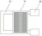
FIG. 3 is a plan view of the expanding and contracting mechanism and the culturing mechanism of the present invention.
In the figure: the device comprises a wall 1, a telescopic mechanism 2, a 21U-shaped plate, a 22 shell, an electric push rod 23, a chute 24, a slide block 25, a connecting rod 26, a culture mechanism 3, a culture basin 31, a filter screen 32, a water leakage hole 33, a water pool 4, a water spraying mechanism 5, a water pump 51, a tee pipe 52, a water inlet pipe 53, a water outlet pipe 54, a spray head 55 and a controller 6.
Detailed Description
The technical solutions in the embodiments of the present invention will be clearly and completely described below with reference to the drawings in the embodiments of the present invention, and it is obvious that the described embodiments are only a part of the embodiments of the present invention, and not all of the embodiments. All other embodiments, which can be derived by a person skilled in the art from the embodiments given herein without making any creative effort, shall fall within the protection scope of the present invention.
Referring to fig. 1-3, the multifunctional landscape wall in this embodiment includes a wall body 1, a telescopic mechanism 2 is disposed on the right side of the wall body 1, a cultivation mechanism 3 is fixedly mounted on the top of the telescopic mechanism 2, a water tank 4 is disposed on the right side of the wall body 1 and below the cultivation mechanism 3, a water spraying mechanism 5 is disposed on the left side of the wall body 1, and a controller 6 is fixedly mounted on the front side of the wall body 1;
the water spraying mechanism 5 comprises a water pump 51, a three-way pipe 52, a water inlet pipe 53, a water outlet pipe 54 and a spray head 55, the water pump 51 is fixedly installed on the left side of the wall body 1, a water inlet of the water pump 51 is communicated with the three-way pipe 52, the bottom of the three-way pipe 52 is communicated with the water inlet pipe 53, one end of the water inlet pipe is penetrated through the wall body 1 and extends to the inside of the water pool 4, a water outlet of the water pump 51 is communicated with the water outlet pipe 54, one end of the water outlet pipe 54 is penetrated through and extends to the right side of the wall body 1, the spray head 55 is communicated with the bottom of the water outlet pipe 54, when the water spraying mechanism is used, the water pump 51 can be started to convey water inside the water pool 4 to the funnel through the spray head 55, when the water flows out from the bottom of the funnel, a waterfall shape can be formed, the fallen water flows into the water pool 4 and is pumped to the funnel again through the water pump 51, and therefore, the display effect is improved, and the water resource is reused.
In this embodiment, the right side of the wall 1 and the lower portion of the nozzle 55 are fixedly provided with the funnel, when in use, water flows out from the bottom of the funnel to form a waterfall shape, the funnel is a stainless steel funnel, and the stainless steel material has good corrosion resistance and heat resistance characteristics and long service life.
In this embodiment, the telescoping mechanism 2 comprises a U-shaped plate 21, two shells 22, an electric push rod 23, two sliding grooves 24, a sliding block 25 and a connecting rod 26, the U-shaped plate 21 is fixedly installed on the right side of the wall 1, the two shells 22 are fixedly installed on the right side of the U-shaped plate 21, the electric push rod 23 is fixedly installed on the right side of the inner wall of the shell 22, the sliding grooves 24 are respectively opened on the front side and the rear side of the inner wall of the U-shaped plate 21, the sliding block 25 is movably installed inside the sliding grooves 24, the connecting rod 26 with one end penetrating through the U-shaped plate 21 and fixedly connected with the sliding block 25 is fixedly installed on the output end of the electric push rod 23, when the automatic watering cultivation pot is used, the controller 6 operates the electric push rod 23 at regular time to drive the sliding block 25 to move leftwards, the sliding block 25 drives the cultivation pot 31 to move leftwards to the lower part of the funnel, so that water falling from the funnel enters the cultivation pot 31, the purpose of automatically watering the cultivation pot 31 for green plants is achieved, and the automatic watering cultivation pot is convenient for a user to use.
In this embodiment, cultivate mechanism 3 including cultivating basin 31, filter screen 32 and hole 33 that leaks, the top fixed mounting of slider 25 has one end to run through and extend to the cultivation basin 31 of U template 21 top, when using, can cultivate the cultivation of green plants such as flowers and plants trees in cultivating basin 31, the inside fixed mounting who cultivates basin 31 has filter screen 32 when using, can come with separating with the separation of water with cultivating soil, the hole 33 that leaks has been seted up to the bottom of cultivating basin 31, when using, can discharge unnecessary moisture.
In this embodiment, the top fixed mounting of wall body 1 has the bottom plate, and the top fixed mounting of bottom plate has the battery, and the top of bottom plate and the top fixed mounting who is located the battery have solar panel, and when using, solar panel can store solar energy transformation for the electric energy in the battery, and the battery provides clear electric energy for equipment, and the bottom fixed mounting of bottom plate has the light, when using, conveniently promotes the ornamental effect at night.
In this embodiment, the left side of the three-way pipe 52 is communicated with a tap water pipe, and a water valve is arranged outside the tap water pipe, so that when the water supply device is used and the water in the water tank 4 is insufficient, the water supply device can supply water to the water tank 4.
In this embodiment, inner wall right side fixed mounting in pond 4 has level sensor, and when using, the inside water level in monitoring pond 4 that can be real-time, level sensor, water valve and water pump 51 all are connected with controller 6 electricity, and when using, the opening of accessible controller 6 automatic control equipment stops.
The working principle of the above embodiment is as follows:
(1) the controller 6 sets a period for watering the green plants in the cultivation basin 31 at regular time, the liquid level sensor can monitor the water level in the water tank 4 in real time, and when the water in the water tank 4 is insufficient, the controller 6 can open the water valve to supplement water for the water pump 51;
(2) the water pump 51 is started to convey water in the water tank 4 into the funnel through the spray nozzle 55, the water can form a waterfall shape when flowing out from the bottom of the funnel, and the falling water flows into the water tank 4 and is pumped into the funnel again by the water pump 51, so that the display effect is improved, and the water resource is recycled;
(3) the controller 6 operates the electric push rod 23 at regular time to drive the sliding block 25 to move leftwards, the sliding block 25 drives the cultivating pot 31 to move leftwards to the lower part of the funnel, so that water falling from the funnel enters the cultivating pot 31, the purpose of automatically watering green plants in the cultivating pot 31 is realized, and the use of a user is facilitated.
It is noted that, herein, relational terms such as first and second, and the like may be used solely to distinguish one entity or action from another entity or action without necessarily requiring or implying any actual such relationship or order between such entities or actions. Also, the terms "comprises," "comprising," or any other variation thereof, are intended to cover a non-exclusive inclusion, such that a process, method, article, or apparatus that comprises a list of elements does not include only those elements but may include other elements not expressly listed or inherent to such process, method, article, or apparatus. Without further limitation, an element defined by the phrase "comprising an … …" does not exclude the presence of other identical elements in a process, method, article, or apparatus that comprises the element.
Although embodiments of the present invention have been shown and described, it will be appreciated by those skilled in the art that changes, modifications, substitutions and alterations can be made in these embodiments without departing from the principles and spirit of the utility model, the scope of which is defined in the appended claims and their equivalents.
Claims (7)
1. The utility model provides a multi-functional landscape wall, includes wall body (1), its characterized in that: the water spraying device is characterized in that a telescopic mechanism (2) is arranged on the right side of the wall body (1), a culture mechanism (3) is fixedly mounted at the top of the telescopic mechanism (2), a water pool (4) is arranged on the right side of the wall body (1) and below the culture mechanism (3), a water spraying mechanism (5) is arranged on the left side of the wall body (1), and a controller (6) is fixedly mounted on the front side of the wall body (1);
the water spraying mechanism (5) comprises a water pump (51), a three-way pipe (52), a water inlet pipe (53), a water outlet pipe (54) and a spray head (55), the water pump (51) is fixedly mounted on the left side of the wall body (1), the water inlet of the water pump (51) is communicated with the three-way pipe (52), the bottom of the three-way pipe (52) is communicated with the water inlet pipe (53) with one end penetrating through the wall body (1) and extending to the inside of the water pool (4), the water outlet of the water pump (51) is communicated with the water outlet pipe (54) with one end penetrating through and extending to the right side of the wall body (1), and the bottom of the water outlet pipe (54) is communicated with the spray head (55).
2. The multi-functional landscape wall of claim 1, characterized in that: the right side of wall body (1) just is located the below fixed mounting of shower nozzle (55) and has the funnel, the funnel is the stainless steel funnel.
3. The multi-functional landscape wall of claim 1, characterized in that: telescopic machanism (2) are including U template (21), casing (22), electric putter (23), spout (24), slider (25) and connecting rod (26), the right side fixed mounting of wall body (1) has U template (21), the right side fixed mounting of U template (21) has casing (22) that quantity is two, the inner wall right side fixed mounting of casing (22) has electric putter (23), spout (24) have all been seted up with the inner wall rear side to the inner wall front side of U template (21), the inside movable mounting of spout (24) has slider (25), the output fixed mounting of electric putter (23) has one end to run through U template (21) and connecting rod (26) with slider (25) fixed connection.
4. The multi-functional landscape wall of claim 3, characterized in that: cultivate mechanism (3) including cultivating basin (31), filter screen (32) and hole (33) that leaks, the top fixed mounting of slider (25) has one end to run through and extend to the cultivation basin (31) of U template (21) top, the inside fixed mounting who cultivates basin (31) has filter screen (32), the hole (33) that leaks has been seted up to the bottom of cultivating basin (31).
5. The multi-functional landscape wall of claim 1, characterized in that: the top fixed mounting of wall body (1) has the bottom plate, the top fixed mounting of bottom plate has the battery, the top of bottom plate and the top fixed mounting who is located the battery have solar panel, the bottom fixed mounting of bottom plate has the light.
6. The multi-functional landscape wall of claim 1, characterized in that: the left side of the three-way pipe (52) is communicated with a tap water pipe, and the outer side of the tap water pipe is provided with a water valve.
7. The multi-functional landscape wall of claim 6, characterized in that: the inner wall right side fixed mounting in pond (4) has level sensor, water valve and water pump (51) all are connected with controller (6) electricity.
Priority Applications (1)
| Application Number | Priority Date | Filing Date | Title |
|---|---|---|---|
| CN202121667174.5U CN215421873U (en) | 2021-07-21 | 2021-07-21 | Multi-functional landscape wall |
Applications Claiming Priority (1)
| Application Number | Priority Date | Filing Date | Title |
|---|---|---|---|
| CN202121667174.5U CN215421873U (en) | 2021-07-21 | 2021-07-21 | Multi-functional landscape wall |
Publications (1)
| Publication Number | Publication Date |
|---|---|
| CN215421873U true CN215421873U (en) | 2022-01-07 |
Family
ID=79683452
Family Applications (1)
| Application Number | Title | Priority Date | Filing Date |
|---|---|---|---|
| CN202121667174.5U Active CN215421873U (en) | 2021-07-21 | 2021-07-21 | Multi-functional landscape wall |
Country Status (1)
| Country | Link |
|---|---|
| CN (1) | CN215421873U (en) |
Cited By (1)
| Publication number | Priority date | Publication date | Assignee | Title |
|---|---|---|---|---|
| CN115182621A (en) * | 2022-07-19 | 2022-10-14 | 厦门晶晟富阳科技有限公司 | Multi-functional photovoltaic wisdom leisure courtyard |
-
2021
- 2021-07-21 CN CN202121667174.5U patent/CN215421873U/en active Active
Cited By (1)
| Publication number | Priority date | Publication date | Assignee | Title |
|---|---|---|---|---|
| CN115182621A (en) * | 2022-07-19 | 2022-10-14 | 厦门晶晟富阳科技有限公司 | Multi-functional photovoltaic wisdom leisure courtyard |
Similar Documents
| Publication | Publication Date | Title |
|---|---|---|
| CN205161272U (en) | Vertical greening device that collection rainwater was collected | |
| CN209002535U (en) | A kind of wall greening irrigation rig | |
| CN215421873U (en) | Multi-functional landscape wall | |
| CN211091080U (en) | Afforestation watering device for landscape planting | |
| CN212993560U (en) | Intelligence sprinkling irrigation formula landscape lamp | |
| CN212053943U (en) | Landscape pavilion integrating top planting and rainwater collecting and irrigating | |
| CN206958802U (en) | A kind of novel energy-saving environment-friendly Landscape Lamp | |
| CN213127453U (en) | A ecological slope of forest garden design for protecting plant | |
| CN211114262U (en) | Outdoor decorative curtain wall with water falling and cooling functions | |
| CN211037576U (en) | Building energy-saving roof heat insulation system | |
| CN207589742U (en) | A kind of vertical planting system | |
| CN217487032U (en) | Ecological landscape based on light greening building | |
| CN212715685U (en) | Ecological roof of green building | |
| CN218163684U (en) | Greening landscape building for city planning and design | |
| CN218456961U (en) | Ornamental potted plant decorative solar lamp | |
| CN218977417U (en) | Gardens water conservation formula pergola | |
| CN213214575U (en) | Agricultural greenhouse capable of collecting and utilizing rainwater | |
| CN213245897U (en) | Ecological basin is suitable for view building | |
| CN217608524U (en) | Convenient wall-mounted green cultivation device | |
| CN218163702U (en) | Flower wall for landscaping | |
| CN209983196U (en) | Plant planting device for landscaping | |
| CN213695197U (en) | Urban household vegetable cultivation box | |
| CN214676732U (en) | Landscape greening device for building external wall | |
| CN211657087U (en) | But automatically regulated's farmland sprinkling irrigation equipment | |
| CN214482387U (en) | Novel greening building wall |
Legal Events
| Date | Code | Title | Description |
|---|---|---|---|
| GR01 | Patent grant | ||
| GR01 | Patent grant |