CN215414839U - Portable concrete panel hardness detection device for building - Google Patents
Portable concrete panel hardness detection device for building Download PDFInfo
- Publication number
- CN215414839U CN215414839U CN202121372853.XU CN202121372853U CN215414839U CN 215414839 U CN215414839 U CN 215414839U CN 202121372853 U CN202121372853 U CN 202121372853U CN 215414839 U CN215414839 U CN 215414839U
- Authority
- CN
- China
- Prior art keywords
- electric telescopic
- fixedly connected
- telescopic rod
- plate
- plc
- Prior art date
- Legal status (The legal status is an assumption and is not a legal conclusion. Google has not performed a legal analysis and makes no representation as to the accuracy of the status listed.)
- Active
Links
Images


Landscapes
- On-Site Construction Work That Accompanies The Preparation And Application Of Concrete (AREA)
Abstract
The utility model discloses a portable concrete plate hardness detection device for buildings, which comprises a workbench, wherein a first electric telescopic rod is electrically connected with a PLC (programmable logic controller) through a circuit, the output end of the first electric telescopic rod is fixedly connected with the top surface of a square frame, a second electric telescopic rod is arranged right above a conical cylinder, the conical cylinder is fixedly sleeved with a toothed ring, the toothed ring is meshed with a gear, the inner side wall of the square frame is fixedly connected with a third electric telescopic rod, the other end of the third electric telescopic rod is fixedly connected with the side wall of an I-shaped plate, the third electric telescopic rod is electrically connected with the PLC through a circuit, the model of a three-phase asynchronous motor is Y2-80M2-4S150, the square frame and a first dovetail block are connected in a welding mode, the concrete plate can be subjected to multi-point detection, meanwhile, the concrete block to be detected is effectively prevented from flying in disorder, the operation is simple, and workers are indirectly protected, the cleaning of the scraps is convenient, the time and the labor are saved, and the using requirements of the building are met.
Description
Technical Field
The utility model relates to the technical field of buildings, in particular to a portable concrete plate hardness detection device for buildings.
Background
Concrete is a general term of engineering composite materials which are formed by combining aggregate into a whole through cementing materials, generally speaking, the term concrete refers to cement which is used as the cementing materials, sand and stone are used as the aggregate, the cement concrete is mixed with water according to a certain proportion, and the cement concrete is obtained through stirring and is widely applied to civil engineering.
SUMMERY OF THE UTILITY MODEL
In order to solve the existing problems, the utility model provides a portable concrete plate hardness detection device for buildings.
The utility model is realized by the following technical scheme:
a portable concrete plate hardness detection device for buildings comprises a workbench, wherein a plurality of supporting legs are symmetrically and fixedly connected to the bottom surface of the workbench, a plurality of grooves are symmetrically formed in the top surface of the workbench, hydraulic cylinders are arranged in the grooves, the bottom surface of each hydraulic cylinder is fixedly connected with the top surface of the workbench, the hydraulic cylinders are communicated with a hydraulic station through pipelines, an n-shaped plate is fixedly connected to the top surface of the workbench, the side walls of the n-shaped plate risers are fixedly connected with a PLC (programmable logic controller), square frames are arranged between the n-shaped plate risers in a laminating sliding mode, first dovetail grooves are formed in the side walls of the n-shaped plate risers, first dovetail blocks are arranged in the first dovetail grooves in a laminating sliding mode, the side walls of the first dovetail blocks are fixedly connected with the side walls of the square frames, two first electric transverse plates are symmetrically and fixedly connected to the bottom surface of the n-shaped plate, and the first electric telescopic rods are electrically connected with the PLC through circuits, the output end of the first electric telescopic rod is fixedly connected with the top surface of the square frame, an I-shaped plate is arranged in the square frame in A laminating and sliding mode, A three-phase asynchronous motor is fixedly connected with the top surface of the I-shaped plate, A gear is fixedly connected with the output end of the three-phase asynchronous motor, A second dovetail groove is formed in the bottom surface of the n-shaped plate transverse plate, A second dovetail block is arranged in the second dovetail groove in A laminating and sliding mode, A second electric telescopic rod is fixedly connected with the bottom surface of the second dovetail block, two electromagnetic plates are symmetrically arranged right below the second electric telescopic rod and are mutually laminated, the electromagnetic plates are electrically connected with A PLC (programmable logic controller) through A circuit, the second electric telescopic rod is electrically connected with the PLC through the circuit, the PLC is in A CPM1A-10CDR-A-V1 type, A balancing weight is arranged on the bottom surface of the electromagnetic plate, and the electromagnetic plate at the bottom end is fixedly embedded in the balancing weight block, the top surface of the top electromagnetic plate is fixedly connected with the bottom surface of the second electric telescopic rod, the bottom surface of the second dovetail block is symmetrically and fixedly connected with two L-shaped rods, a circular ring is fixedly connected between the cross rods of the two L-shaped rods, a conical cylinder is arranged in the circular ring in a fitting and rotating manner, threads are arranged at the bottom of the conical cylinder, the bottom end of the conical cylinder penetrates through the I-shaped plate to be fitted with the top surface of the workbench, the conical cylinder is rotationally connected with the I-shaped plate, two limiting rings are fixedly sleeved on the conical cylinder, the two limiting rings are positioned at two sides of the I-shaped plate and are jointed with the surface of the I-shaped plate, the second electric telescopic rod is arranged right above the conical cylinder, a toothed ring is fixedly sleeved on the conical cylinder, the gear ring is meshed with the gear, the inner side wall of the square frame is fixedly connected with a third electric telescopic rod, the other end of the third electric telescopic rod is fixedly connected with the side wall of the I-shaped plate, and the third electric telescopic rod is electrically connected with the PLC through a circuit.
Preferably, the model of the three-phase asynchronous motor is Y2-80M2-4S 150.
Preferably, the square frame and the first dovetail block are connected by welding.
Compared with the prior art, the utility model has the beneficial effects that: this device simple structure, the function is various, therefore, the clothes hanger is strong in practicability, through setting up the n-shaped plate, the PLC controller, square frame, first dovetail piece, first electric telescopic handle, I-shaped plate, three-phase asynchronous machine, the gear, second dovetail piece, second electric telescopic handle, the electromagnetic plate, the balancing weight, L shape pole, the ring, the taper cylinder, the spacing ring, effectual preventing when ring gear and third electric telescopic handle can carry out the multiple spot to concrete panel detects waits to detect concrete block and flies in disorder, and is simple in operation, the indirect staff that has protected, the clearance of the sweeps of also being convenient for, and is time-saving and labor-saving, satisfies the building user demand.
Drawings
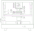
FIG. 1 is a block diagram of the present invention;
FIG. 2 is a top view of the structure of the present invention;
FIG. 3 is a schematic representation of the operation of the structure of the present invention;
fig. 4 is a schematic diagram of the operation of the structure of the present invention.
In the figure: the device comprises a workbench 1, a hydraulic cylinder 2, an n-shaped plate 3, a PLC 4, a square frame 5, a first dovetail block 6, a first electric telescopic rod 7, an I-shaped plate 8, a three-phase asynchronous motor 9, a gear 10, a second dovetail block 11, a second electric telescopic rod 12, an electromagnetic plate 13, a balancing weight 14, an L-shaped rod 15, a circular ring 16, a conical cylinder 17, a limiting ring 18, a toothed ring 19, a third electric telescopic rod 20, a groove 1-1, a first dovetail groove 2-1 and a second dovetail groove 2-2.
Detailed Description
The utility model is described in further detail below with reference to the following detailed description and accompanying drawings:
as shown in figures 1, 2, 3 and 4, the portable concrete plate hardness detection device for the building comprises a workbench 1, wherein a plurality of support legs are symmetrically and fixedly connected to the bottom surface of the workbench 1, a plurality of grooves 1-1 are symmetrically formed in the top surface of the workbench 1, hydraulic cylinders 2 are arranged in the grooves 1-1, the bottom surface of each hydraulic cylinder 2 is fixedly connected with the top surface of the workbench 1, the hydraulic cylinders 2 are communicated with a hydraulic station through pipelines, an n-shaped plate 3 is fixedly connected to the top surface of the workbench 1, a PLC (programmable logic controller) 4 is fixedly connected to the side wall of each n-shaped plate 3, a square frame 5 is arranged between the risers of the n-shaped plate 3 in a laminating and sliding manner, a first dovetail groove 2-1 is formed in the side wall of each n-shaped plate 3, a first dovetail block 6 is arranged in each first dovetail groove 2-1 in a laminating and sliding manner, and the side wall of each first dovetail block 6 is fixedly connected with the side wall of the square frame 5, the bottom surface of the transverse plate of the n-shaped plate 3 is symmetrically and fixedly connected with two first electric telescopic rods 7, the first electric telescopic rods 7 are electrically connected with a PLC (programmable logic controller) 4 through a circuit, the output end of the first electric telescopic rod 7 is fixedly connected with the top surface of a square frame 5, an I-shaped plate 8 is arranged in the square frame 5 in a laminating and sliding manner, the top surface of the I-shaped plate 8 is fixedly connected with a three-phase asynchronous motor 9, the output end of the three-phase asynchronous motor 9 is fixedly connected with a gear 10, the bottom surface of the transverse plate of the n-shaped plate 3 is provided with a second dovetail groove 2-2, a second dovetail block 11 is arranged in the second dovetail groove 2-2 in a laminating and sliding manner, the bottom surface of the second dovetail block 11 is fixedly connected with a second electric telescopic rod 12, two electromagnetic plates 13 are symmetrically arranged under the second electric telescopic rod 12, the two electromagnetic plates 13 are mutually laminated, and the electromagnetic plates 13 are electrically connected with the PLC 4 through a circuit, the second electric telescopic rod 12 is electrically connected with A PLC (programmable logic controller) 4 through A circuit, the model of the PLC 4 is CPM1A-10CDR-A-V1, A counterweight 14 is arranged on the bottom surface of an electromagnetic plate 13 at the bottom end, the electromagnetic plate 13 at the bottom end is fixedly embedded in the counterweight 14, the top surface of the electromagnetic plate 13 at the top end is fixedly connected with the bottom surface of the second electric telescopic rod 12, two L-shaped rods 15 are symmetrically and fixedly connected with the bottom surface of A second dovetail block 11, A circular ring 16 is fixedly connected between the transverse rods of the two L-shaped rods 15, A conical cylinder 17 is arranged in the circular ring 16 in A fitting and rotating mode, threads are arranged at the bottom of the conical cylinder 17, the bottom end of the conical cylinder 17 penetrates through A I-shaped plate 8 to be fitted with the top surface of A workbench 1, the conical cylinder 17 is rotatably connected with the I-shaped plate 8, two limiting rings 18 are fixedly sleeved on the conical cylinder 17, the two limiting rings 18 are positioned on two sides of the I-shaped plate 8 and are fitted with the surface of the I-shaped plate, the second electric telescopic handle 12 is arranged right above the conical barrel 17, a toothed ring 19 is fixedly sleeved on the conical barrel 17, the toothed ring 19 is meshed with the gear 10, a third electric telescopic handle 20 is fixedly connected to the inner side wall of the square frame 5, the other end of the third electric telescopic handle 20 is fixedly connected with the side wall of the I-shaped plate 8, and the third electric telescopic handle 20 is electrically connected with the PLC controller 4 through a circuit.
The model number of the three-phase asynchronous motor 9 is Y2-80M2-4S 150.
The square frame 5 and the first dovetail block 6 are connected by welding.
The working principle is as follows: when a concrete plate needs to be detected, the device is firstly connected with a power supply, then the concrete plate needing to be detected is placed on the workbench 1, then the PLC 4 is operated to enable the first electric telescopic rod 7 and the three-phase asynchronous motor 9 to start working, the output end of the three-phase asynchronous motor 9 drives the gear 10 to rotate, the gear 10 drives the gear ring 19 to rotate, the gear ring 19 drives the conical cylinder 17 to rotate, meanwhile, the output end of the first electric telescopic rod 7 pushes the square frame 5 to move, the square frame 5 drives the I-shaped plate 8 to move, the I-shaped plate 8 drives the limiting ring 18 to move, the limiting ring 18 drives the conical cylinder 17 to move, so that the conical cylinder 17 rotates and moves downwards to drill the concrete plate, when the output end of the first electric telescopic rod 7 extends to be the longest, the bottom end of the conical cylinder 17 just fits the top surface of the workbench 1 at the moment, as shown in figure 3, at the moment, the concrete block to be detected enters the conical barrel 17, the hydraulic station is operated to enable the hydraulic cylinder 2 to start working, the output end of the hydraulic cylinder 2 pushes the concrete plate to move upwards for a certain distance and then stops moving, then the PLC 4 is operated to enable the three-phase asynchronous motor 9 to stop working, then the PLC 4 is operated to enable the power between the two electromagnetic plates 13 to be cut off, the counterweight block 14 descends, the counterweight block 14 drives the electromagnetic plate 13 at the bottom end to descend, the counterweight block 14 descends and gradually enters the conical barrel 17 to be pricked on the concrete block to be detected, as shown in figure 4, the PLC 4 is operated to enable the electromagnetic plate 13 to be electrified and simultaneously enable the second electric telescopic rod 12 to start working, the output end of the second electric telescopic rod 12 drives the electromagnetic plate 13 to move and gradually move into the conical barrel 17, the electromagnetic plate 13 at the top end descends and gradually adsorbs the electromagnetic plate 13 at the bottom end, and then the PLC 4 is operated to enable the second electric telescopic rod 12 to contract, the output end of the second electric telescopic rod 12 indirectly drives the balancing weight 14 to slide out of the conical cylinder 17, then the PLC controller 4 is operated to enable the first electric telescopic rod 7 to start working, the output end of the first electric telescopic rod 7 indirectly drives the conical cylinder 17 to move upwards, a concrete block to be detected slides out of the conical cylinder 17, if the concrete block to be detected is not broken, the concrete plate is proved to be qualified, otherwise the concrete plate is not qualified, when another point of the concrete plate is detected, after the detected concrete block to be detected is cleaned, the hydraulic cylinder 2 is operated to start working, the output end of the hydraulic cylinder 2 gradually descends, the concrete plate gradually descends due to gravity, the concrete plate stops moving after being attached to the top surface of the workbench 1, then the PLC controller 4 is operated to enable the third electric telescopic rod 20 to start working, the output end of the third electric telescopic rod 20 drives the I-shaped plate 8 to move, the I-shaped plate 8 drives the limiting ring 18 to move, the limiting ring 18 drives the conical barrel 17, the conical barrel 17 drives the circular ring 16 to move, the circular ring 16 drives the L-shaped rod 15 to move, the L-shaped rod 15 drives the second dovetail block 11 to slide in the second dovetail groove 2-2, the second dovetail block 11 drives the second electric telescopic rod 12 to move, the second electric telescopic rod 12 drives the electromagnetic plate 13 to move, the electromagnetic plate 13 drives the balancing weight 14 to move, when the conical barrel 17 moves to a position right above a point to be detected of a concrete plate, the PLC 4 is operated to stop the third electric telescopic rod 20, then the hardness detection of the concrete plate is carried out according to the operation, after the hardness detection of the concrete plate is finished, the PLC 4 is operated to stop all electrical equipment of the device, finally, the device is separated from a power supply, and the setting of the limiting ring 18 plays an effective limiting role.
The foregoing illustrates and describes the principles, general features, and advantages of the present invention. It will be understood by those skilled in the art that the present invention is not limited to the embodiments described above, which are described in the specification and illustrated only to illustrate the principle of the present invention, but that various changes and modifications may be made therein without departing from the spirit and scope of the present invention, which fall within the scope of the utility model as claimed. The scope of the utility model is defined by the appended claims and equivalents thereof.
Claims (3)
1. The utility model provides a portable concrete panel hardness detection device for building, includes workstation (1), a plurality of landing legs of workstation (1) bottom surface symmetry fixedly connected with, its characterized in that: the top surface of the workbench (1) is symmetrically provided with a plurality of grooves (1-1), the grooves (1-1) are internally provided with hydraulic cylinders (2), the bottom surfaces of the hydraulic cylinders (2) are fixedly connected with the top surface of the workbench (1), the hydraulic cylinders (2) are communicated with a hydraulic station through pipelines, the top surface of the workbench (1) is fixedly connected with n-shaped plates (3), the side walls of the n-shaped plates (3) are fixedly connected with a PLC (programmable logic controller) (4), square frames (5) are arranged between the n-shaped plates (3) in a laminating and sliding manner, the side walls of the n-shaped plates (3) are provided with first dovetail grooves (2-1), first dovetail blocks (6) are arranged in the first dovetail grooves (2-1) in a laminating and sliding manner, the side walls of the first dovetail blocks (6) are fixedly connected with the side walls of the square frames (5), the bottom surfaces of the transverse plates of the n-shaped plates (3) are symmetrically and fixedly connected with two first electric telescopic rods (7), the first electric telescopic rod (7) is electrically connected with the PLC (4) through a circuit, the output end of the first electric telescopic rod (7) is fixedly connected with the top surface of the square frame (5), the I-shaped plate (8) is arranged in the square frame (5) in a laminating and sliding mode, the top surface of the I-shaped plate (8) is fixedly connected with a three-phase asynchronous motor (9), the output end of the three-phase asynchronous motor (9) is fixedly connected with a gear (10), the bottom surface of the transverse plate of the n-shaped plate (3) is provided with a second dovetail groove (2-2), a second dovetail block (11) is arranged in the second dovetail groove (2-2) in a laminating and sliding mode, the bottom surface of the second dovetail block (11) is fixedly connected with a second electric telescopic rod (12), two electromagnetic plates (13) are symmetrically arranged under the second electric telescopic rod (12), and the two electromagnetic plates (13) are mutually laminated, the electromagnetic plate (13) is electrically connected with A PLC (programmable logic controller) (4) through A circuit, the second electric telescopic rod (12) is electrically connected with the PLC (4) through A circuit, the PLC (4) is of the type CPM1A-10CDR-A-V1, A counterweight (14) is arranged on the bottom surface of the electromagnetic plate (13) at the bottom end, the electromagnetic plate (13) at the bottom end is fixedly embedded in the counterweight (14), the top surface of the electromagnetic plate (13) at the top end is fixedly connected with the bottom surface of the second electric telescopic rod (12), two L-shaped rods (15) are symmetrically and fixedly connected with the bottom surface of the second dovetail block (11), A circular ring (16) is fixedly connected between the cross rods of the two L-shaped rods (15), A conical cylinder (17) is rotatably arranged in the circular ring (16) in an attached mode, threads are arranged at the bottom of the conical cylinder (17), and the bottom end of the conical cylinder (17) penetrates through an I-shaped plate (8) to be attached to the top surface of the workbench (1), a toper section of thick bamboo (17) and worker word board (8) swivelling joint, fixed cover has two spacing rings (18) on a toper section of thick bamboo (17), and two spacing rings (18) are located worker word board (8) both sides and rather than the surface laminating, second electric telescopic handle (12) set up directly over a toper section of thick bamboo (17), fixed cover has ring gear (19) on a toper section of thick bamboo (17), ring gear (19) and gear (10) meshing, square frame (5) inside wall fixedly connected with third electric telescopic handle (20), third electric telescopic handle (20) other end and worker word board (8) lateral wall fixed connection, third electric telescopic handle (20) pass through circuit and PLC controller (4) electric connection.
2. The portable concrete plate hardness detection device for building of claim 1, characterized in that: the model of the three-phase asynchronous motor (9) is Y2-80M2-4S 150.
3. The portable concrete plate hardness detection device for building of claim 1, characterized in that: the square frame (5) and the first dovetail block (6) are connected in a welding mode.
Priority Applications (1)
| Application Number | Priority Date | Filing Date | Title |
|---|---|---|---|
| CN202121372853.XU CN215414839U (en) | 2021-06-21 | 2021-06-21 | Portable concrete panel hardness detection device for building |
Applications Claiming Priority (1)
| Application Number | Priority Date | Filing Date | Title |
|---|---|---|---|
| CN202121372853.XU CN215414839U (en) | 2021-06-21 | 2021-06-21 | Portable concrete panel hardness detection device for building |
Publications (1)
| Publication Number | Publication Date |
|---|---|
| CN215414839U true CN215414839U (en) | 2022-01-04 |
Family
ID=79640415
Family Applications (1)
| Application Number | Title | Priority Date | Filing Date |
|---|---|---|---|
| CN202121372853.XU Active CN215414839U (en) | 2021-06-21 | 2021-06-21 | Portable concrete panel hardness detection device for building |
Country Status (1)
| Country | Link |
|---|---|
| CN (1) | CN215414839U (en) |
-
2021
- 2021-06-21 CN CN202121372853.XU patent/CN215414839U/en active Active
Similar Documents
| Publication | Publication Date | Title |
|---|---|---|
| CN103741955B (en) | automatic wall building machine | |
| CN104971912B (en) | Ceramic tile cleaning device | |
| CN205552905U (en) | Automatic groover of ceramic tile | |
| CN106284952A (en) | A kind of intelligence ceramic tile stickers machine people | |
| CN104070568A (en) | Batten splicing and forming device | |
| CN215414839U (en) | Portable concrete panel hardness detection device for building | |
| CN203714840U (en) | Bridge type setting machine | |
| CN106150042B (en) | Gua Qiang robots | |
| CN209337623U (en) | A kind of autoclave aerated concrete building block folder fetus device | |
| CN202023343U (en) | Full-automatic wall plasterer | |
| CN211194506U (en) | Ceramic tile cutting device for construction | |
| CN207206543U (en) | A kind of PCB substrate automatic slotting machine | |
| CN104179338B (en) | Plaster a wall smooth all-in-one at a high speed | |
| CN202577915U (en) | Pasting machine | |
| CN204680987U (en) | The device that a kind of temporary electricity of constructing is arranged | |
| CN213231280U (en) | Lifting device with protection effect for decoration construction | |
| CN108265966A (en) | A kind of construction safety hanging basket and its implementation | |
| CN203382703U (en) | Solvent type fireproof coating production device | |
| CN211007566U (en) | Portable construction frame | |
| CN210732705U (en) | Arrange rig and arrange sediment device | |
| CN203867150U (en) | Wall plastering machine | |
| CN210369784U (en) | Ceramic tile soaking device for interior design and decoration | |
| CN208072985U (en) | A kind of Shimizu concrete template piece fitting machine | |
| CN203626210U (en) | Electric trowel machine special for self-leveling floor | |
| CN207211717U (en) | Rapid forming mold for the house free of demolition of environment-friendly energy-saving |
Legal Events
| Date | Code | Title | Description |
|---|---|---|---|
| GR01 | Patent grant | ||
| GR01 | Patent grant |