CN215388220U - Bag type pulse dust collector capable of easily cleaning dust - Google Patents
Bag type pulse dust collector capable of easily cleaning dust Download PDFInfo
- Publication number
- CN215388220U CN215388220U CN202120939378.3U CN202120939378U CN215388220U CN 215388220 U CN215388220 U CN 215388220U CN 202120939378 U CN202120939378 U CN 202120939378U CN 215388220 U CN215388220 U CN 215388220U
- Authority
- CN
- China
- Prior art keywords
- shell
- dust
- fixedly connected
- bag
- inlet pipe
- Prior art date
- Legal status (The legal status is an assumption and is not a legal conclusion. Google has not performed a legal analysis and makes no representation as to the accuracy of the status listed.)
- Active
Links
Images


Abstract
The utility model discloses a bag type pulse dust collector easy to clean dust, which comprises a shell, wherein the top of the shell is fixedly connected with a protective shell, the left side of the protective shell is communicated with an air inlet pipe, the right side of the air inlet pipe penetrates through the left side of the protective shell and extends to an inner cavity of the protective shell, the bottom of the air inlet pipe is communicated with an air injection pipe, the inner cavity of the shell is fixedly connected with a connecting plate, and the bottom of the connecting plate is fixedly connected with a dust collection filter bag. According to the utility model, through the matched use of the shell, the protective shell, the air inlet pipe, the air injection pipe, the connecting plate, the dedusting filter bag, the air outlet pipe, the dust inlet pipe, the blanking hopper, the motor, the rotating rod, the cam, the access door and the fastener, the problem that the surface of a cloth bag cannot be effectively cleaned in the use process of the traditional pulse bag-type dust remover can be effectively solved, and the device can vibrate the cloth bag, so that the cleaning effect of dust on the surface of the cloth bag is accelerated, the dust cleaning efficiency is improved, and the operation is more convenient.
Description
Technical Field
The utility model relates to the technical field of bag-type dust collectors, in particular to a bag-type pulse dust collector capable of easily cleaning dust.
Background
The pulse bag-type dust collector is formed from dust hopper, upper box body, middle box body and lower box body, and is characterized by that when it is worked, the dust-containing gas can be fed into the dust hopper from air inlet channel, the coarse dust granules can be directly fallen into the bottom of dust hopper, the fine dust granules can be upwards fed into the middle and lower box bodies along with air flow, and the dust can be deposited on the external surface of filter bag, and the filtered gas can be fed into upper box body and air-cleaning collecting pipe, and discharged into atmosphere by means of exhaust fan The pulse valve, the dust discharging valve and the like are controlled fully automatically, and when the traditional pulse bag dust remover is used for bag-type dust removal at present, the residual dust on the surface of a bag is difficult to be completely removed through high-pressure gas, so that the using effect of the bag-type dust removal is influenced.
SUMMERY OF THE UTILITY MODEL
The utility model aims to provide a bag type pulse dust collector capable of easily cleaning dust, which has the advantage of improving the cleaning performance and solves the problem that the residual dust on the surface of a bag is not easily and completely cleaned through high-pressure gas when the conventional pulse bag dust collector is used for bag-type dust collection, so that the using effect of the bag-type dust collection is influenced.
In order to achieve the purpose, the utility model provides the following technical scheme: a cloth bag type pulse dust collector easy to clean dust comprises a shell, wherein a protective shell is fixedly connected to the top of the shell, an air inlet pipe is communicated with the left side of the protective shell, the right side of the air inlet pipe penetrates through the left side of the protective shell and extends to an inner cavity of the protective shell, an air injection pipe is communicated with the bottom of the air inlet pipe, a connecting plate is fixedly connected to the inner cavity of the shell, a dust removal filter bag is fixedly connected to the bottom of the connecting plate, the bottom of the air injection pipe extends to the inner cavity of the dust removal filter bag, an air outlet pipe is communicated with the top of the left side of the shell, a dust inlet pipe is communicated with the bottom of the right side of the shell, a discharging hopper is communicated with the bottom of the shell, a motor is fixedly connected to the bottom of the left side of the shell, a rotating rod is fixedly connected to the output end of the motor, the right side of the rotating rod penetrates through the left side of the shell and extends to the inner cavity of the shell, and a cam is fixedly connected to the surface of the rotating rod, the top of the cam is in contact with the bottom of the dust removal filter bag, an access door is arranged on the surface of the shell, and a fastener is fixedly connected to the surface of the access door.
Preferably, the right side fixedly connected with fixed block of shell inner chamber bottom, the left side of fixed block passes through bearing and bull stick swing joint.
Preferably, the bottom of the motor is fixedly connected with a supporting seat, and the right side of the supporting seat is fixedly connected with the shell.
Preferably, the left side of the air inlet pipe is communicated with a compressed air pump, and the surface of the air inlet pipe is fixedly connected with a pulse electromagnetic valve.
Preferably, both sides of the bottom of the shell are fixedly connected with supporting columns, and one side opposite to the supporting columns is fixedly connected with reinforcing rods.
Preferably, the right side of the inner cavity of the shell is fixedly connected with a baffle, and the bottom of the discharging hopper is communicated with a discharging pipe.
Compared with the prior art, the utility model has the following beneficial effects:
1. according to the utility model, through the matched use of the shell, the protective shell, the air inlet pipe, the air injection pipe, the connecting plate, the dedusting filter bag, the air outlet pipe, the dust inlet pipe, the blanking hopper, the motor, the rotating rod, the cam, the access door and the fastener, the problem that the surface of a cloth bag cannot be effectively cleaned in the use process of the traditional pulse bag-type dust remover can be effectively solved, and the device can vibrate the cloth bag, so that the cleaning effect of dust on the surface of the cloth bag is accelerated, the dust cleaning efficiency is improved, the operation is more convenient and faster, and the maintenance sequence is reduced.
2. The device comprises a rotating rod, a fixing block, a supporting seat, a supporting column and a reinforcing rod, wherein the rotating rod is arranged on the supporting seat, the fixing block is arranged on the rotating rod, the rotating rod can be supported, so that the stability of the rotating rod in the rotating process is guaranteed, high-pressure gas can be produced through the compressed air pump and the pulse electromagnetic valve, the purpose of cloth bag dust removal is achieved, the motor can be supported through the supporting seat, so that the stability of the device is guaranteed, the dust can be blocked through the supporting column and the reinforcing rod, and the purpose of efficient dust removal is achieved.
Drawings
FIG. 1 is a schematic structural view of the present invention;
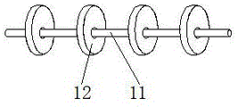
FIG. 2 is a schematic view of a connecting structure of the rotating rod and the cam according to the present invention;
fig. 3 is a schematic front view of the structure of the present invention.
In the figure: 1. a housing; 2. a protective shell; 3. an air inlet pipe; 4. a gas ejector tube; 5. a connecting plate; 6. a dust removal filter bag; 7. an air outlet pipe; 8. a dust inlet pipe; 9. feeding a hopper; 10. a motor; 11. a rotating rod; 12. a cam; 13. an access door; 14. a fastener; 15. a fixed block; 16. a supporting seat; 17. a compressed air pump; 18. a pulse electromagnetic valve; 19. a support pillar; 20. a reinforcing rod; 21. a baffle plate; 22. and (5) discharging the material pipe.
Detailed Description
The technical solutions in the embodiments of the present invention will be clearly and completely described below with reference to the drawings in the embodiments of the present invention, and it is obvious that the described embodiments are only a part of the embodiments of the present invention, and not all of the embodiments. All other embodiments, which can be derived by a person skilled in the art from the embodiments given herein without making any creative effort, shall fall within the protection scope of the present invention.
In the description of the present invention, it should be noted that the terms "upper", "lower", "inner", "outer", "front", "rear", "both ends", "one end", "the other end", and the like indicate orientations or positional relationships based on the orientations or positional relationships shown in the drawings, and are only for convenience of describing the present invention and simplifying the description, but do not indicate or imply that the referred device or element must have a specific orientation, be constructed in a specific orientation, and be operated, and thus, should not be construed as limiting the present invention. Furthermore, the terms "first" and "second" are used for descriptive purposes only and are not to be construed as indicating or implying relative importance.
In the description of the present invention, it is to be noted that, unless otherwise explicitly specified or limited, the terms "mounted", "provided", "connected", and the like are to be construed broadly, such as "connected", which may be fixedly connected, detachably connected, or integrally connected; can be mechanically or electrically connected; they may be connected directly or indirectly through intervening media, or they may be interconnected between two elements. The specific meanings of the above terms in the present invention can be understood in specific cases to those skilled in the art.
The components used in the present invention are all standard components or components known to those skilled in the art, and the structure and principle thereof can be known to those skilled in the art through technical manuals or through routine experiments.
Referring to fig. 1-3, a bag-type pulse dust collector easy to clean dust comprises a housing 1, a fixed block 15 is fixedly connected to the right side of the bottom of an inner cavity of the housing 1, the left side of the fixed block 15 is movably connected with a rotating rod 11 through a bearing, support columns 19 are fixedly connected to both sides of the bottom of the housing 1, a reinforcing rod 20 is fixedly connected to one side opposite to the support columns 19, a baffle 21 is fixedly connected to the right side of the inner cavity of the housing 1, a blanking pipe 22 is communicated with the bottom of a blanking hopper 9, a protective shell 2 is fixedly connected to the top of the housing 1, an air inlet pipe 3 is communicated with the left side of the protective shell 2, a compressed air pump 17 is communicated with the left side of the air inlet pipe 3, a pulse electromagnetic valve 18 is fixedly connected to the surface of the air inlet pipe 3, the right side of the air inlet pipe 3 penetrates through the left side of the protective shell 2 and extends to the inner cavity of the protective shell 2, an air injection pipe 4 is communicated with the bottom of the air inlet pipe 3, and a connecting plate 5 is fixedly connected with the inner cavity of the housing 1, the bottom of the connecting plate 5 is fixedly connected with a dust-removing filter bag 6, the bottom of the air injection pipe 4 extends to the inner cavity of the dust-removing filter bag 6, the left top of the shell 1 is communicated with an air outlet pipe 7, the right bottom of the shell 1 is communicated with a dust inlet pipe 8, the bottom of the shell 1 is communicated with a blanking hopper 9, the left bottom of the shell 1 is fixedly connected with a motor 10, the bottom of the motor 10 is fixedly connected with a supporting seat 16, the right side of the supporting seat 16 is fixedly connected with the shell 1, the output end of the motor 10 is fixedly connected with a rotating rod 11, the right side of the rotating rod 11 penetrates through the left side of the shell 1 and extends to the inner cavity of the shell 1, the surface of the rotating rod 11 is fixedly connected with a cam 12, the top of the cam 12 is contacted with the bottom of the dust-removing filter bag 6, the surface of the shell 1 is provided with an access door 13, the surface of the access door 13 is fixedly connected with a fastener 14, through the arrangement of a fixing block 15, the rotating rod 11 can be supported, thereby ensuring the stability of the rotating rod 11 in the rotating process, producing high-pressure gas to achieve the aim of bag-type dust removal by arranging a compressed air pump 17 and a pulse electromagnetic valve 18, supporting the motor 10 by a supporting seat 16, ensuring the stability of the motor 10, supporting the device by arranging a supporting column 19 and a reinforcing rod 20, further ensuring the stability of the device, blocking dust by arranging a baffle 21, thereby achieving the aim of high-efficiency dust removal, and effectively solving the problem that the surface of a bag of the traditional pulse bag-type dust remover cannot be effectively cleaned in the using process by matching the shell 1, the protective shell 2, the air inlet pipe 3, the air injection pipe 4, the connecting plate 5, the dust-removing filter bag 6, the air outlet pipe 7, the dust inlet pipe 8, the blanking hopper 9, the motor 10, the rotating rod 11, the cam 12, the access door 13 and the fastening piece 14, the device can vibrate through to the sack to the clearance effect of sack surface dust has improved the deashing efficiency, and the operation is more convenient, has reduced and has overhauld the order.
During the use, need when clearing up the dust to this bag type pulse dust remover, through external controller starter motor 10, motor 10 drives bull stick 11 and rotates, and bull stick 11 drives cam 12 and rotates, and cam 12 vibrates dust bag 6 to can accelerate the clearance effect to dust bag 6, avoid the filter effect of surface gathering dust influence equipment.
Although embodiments of the present invention have been shown and described, it will be appreciated by those skilled in the art that changes, modifications, substitutions and alterations can be made in these embodiments without departing from the principles and spirit of the utility model, the scope of which is defined in the appended claims and their equivalents.
Claims (6)
1. The utility model provides a bag type pulse dust collector of easy clearance dust, includes shell (1), its characterized in that: the dust removing device is characterized in that a protective shell (2) is fixedly connected to the top of the shell (1), an air inlet pipe (3) is communicated with the left side of the protective shell (2), the right side of the air inlet pipe (3) penetrates through the left side of the protective shell (2) and extends to the inner cavity of the protective shell (2), an air jet pipe (4) is communicated with the bottom of the air inlet pipe (3), a connecting plate (5) is fixedly connected to the inner cavity of the shell (1), a dust removing filter bag (6) is fixedly connected to the bottom of the connecting plate (5), the bottom of the air jet pipe (4) extends to the inner cavity of the dust removing filter bag (6), an air outlet pipe (7) is communicated with the left top of the shell (1), a dust inlet pipe (8) is communicated with the right bottom of the shell (1), a discharging hopper (9) is communicated with the bottom of the shell (1), and a motor (10) is fixedly connected to the left bottom of the shell (1), the dust removal filter bag dust removal device is characterized in that an output end of the motor (10) is fixedly connected with a rotating rod (11), the right side of the rotating rod (11) penetrates through the left side of the shell (1) and extends to the inner cavity of the shell (1), a cam (12) is fixedly connected to the surface of the rotating rod (11), the top of the cam (12) is in contact with the bottom of the dust removal filter bag (6), an access door (13) is arranged on the surface of the shell (1), and a fastener (14) is fixedly connected to the surface of the access door (13).
2. The bag-type pulse dust collector easy to clean dust of claim 1, which is characterized in that: the right side fixedly connected with fixed block (15) of shell (1) inner chamber bottom, the left side of fixed block (15) is through bearing and bull stick (11) swing joint.
3. The bag-type pulse dust collector easy to clean dust of claim 1, which is characterized in that: the bottom fixedly connected with supporting seat (16) of motor (10), the right side and shell (1) fixed connection of supporting seat (16).
4. The bag-type pulse dust collector easy to clean dust of claim 1, which is characterized in that: the left side of the air inlet pipe (3) is communicated with a compressed air pump (17), and the surface of the air inlet pipe (3) is fixedly connected with a pulse electromagnetic valve (18).
5. The bag-type pulse dust collector easy to clean dust of claim 1, which is characterized in that: the supporting column (19) is fixedly connected to the two sides of the bottom of the shell (1), and the reinforcing rod (20) is fixedly connected to one side, opposite to the supporting column (19).
6. The bag-type pulse dust collector easy to clean dust of claim 1, which is characterized in that: the right side fixedly connected with baffle (21) of shell (1) inner chamber, the bottom intercommunication of lower hopper (9) has unloading pipe (22).
Priority Applications (1)
| Application Number | Priority Date | Filing Date | Title |
|---|---|---|---|
| CN202120939378.3U CN215388220U (en) | 2021-05-06 | 2021-05-06 | Bag type pulse dust collector capable of easily cleaning dust |
Applications Claiming Priority (1)
| Application Number | Priority Date | Filing Date | Title |
|---|---|---|---|
| CN202120939378.3U CN215388220U (en) | 2021-05-06 | 2021-05-06 | Bag type pulse dust collector capable of easily cleaning dust |
Publications (1)
| Publication Number | Publication Date |
|---|---|
| CN215388220U true CN215388220U (en) | 2022-01-04 |
Family
ID=79673970
Family Applications (1)
| Application Number | Title | Priority Date | Filing Date |
|---|---|---|---|
| CN202120939378.3U Active CN215388220U (en) | 2021-05-06 | 2021-05-06 | Bag type pulse dust collector capable of easily cleaning dust |
Country Status (1)
| Country | Link |
|---|---|
| CN (1) | CN215388220U (en) |
Cited By (1)
| Publication number | Priority date | Publication date | Assignee | Title |
|---|---|---|---|---|
| CN114939312A (en) * | 2022-05-12 | 2022-08-26 | 北京策菲节能环保技术有限公司 | High-temperature long-bag pulse bag type dust removal equipment and dust removal method thereof |
-
2021
- 2021-05-06 CN CN202120939378.3U patent/CN215388220U/en active Active
Cited By (2)
| Publication number | Priority date | Publication date | Assignee | Title |
|---|---|---|---|---|
| CN114939312A (en) * | 2022-05-12 | 2022-08-26 | 北京策菲节能环保技术有限公司 | High-temperature long-bag pulse bag type dust removal equipment and dust removal method thereof |
| CN114939312B (en) * | 2022-05-12 | 2023-12-12 | 会东县成瑞稷安矿业有限公司 | High-temperature long-bag pulse bag type dust removal equipment and dust removal method thereof |
Similar Documents
| Publication | Publication Date | Title |
|---|---|---|
| CN215388220U (en) | Bag type pulse dust collector capable of easily cleaning dust | |
| CN216092668U (en) | Waste gas treatment's sack cleaner is used in lead bullion production | |
| CN110694411A (en) | Device for improving efficiency of electric dust collector and reducing resistance of bag dust collector | |
| CN112191045A (en) | Environment-friendly sack dust shaker | |
| CN219922416U (en) | Movable particulate matter removing equipment | |
| CN216092754U (en) | Mould board dust remover that burns | |
| CN214182234U (en) | Powder cleaning mechanism of industrial dust collector | |
| CN215026989U (en) | Device for improving dust removal efficiency of bag-type dust remover | |
| CN214075598U (en) | Semi-dry desulfurization and denitrification device bag-type dust collector | |
| CN211753273U (en) | Dust removal device in aging experiment box | |
| CN209952500U (en) | Dust removal unit suitable for powdery dust and smoke dust | |
| CN220495850U (en) | Pulse type cloth bag dust collector | |
| CN218653451U (en) | Pulse bag dust collector for preparing autoclaved aerated concrete plate | |
| CN215085613U (en) | Novel pulse bag-type dust collector | |
| CN218944598U (en) | Ash removal structure of sack cleaner | |
| CN217909419U (en) | Flat bag type long bag low-pressure pulse dust collector | |
| CN220424799U (en) | Explosion-proof type sack cleaner | |
| CN218901162U (en) | High-efficiency low-resistance pulse dust collector for slowing down airflow impact | |
| CN219128622U (en) | Pulse bag type dust collector is spouted to centrifuging tube | |
| CN214106315U (en) | Novel high-efficient whirlwind removes dust device | |
| CN213668491U (en) | High-efficient dust collector of biomass boiler | |
| CN219581323U (en) | Material dust collection and treatment device for spice production | |
| CN220026371U (en) | Exhaust gas purification pulse cloth bag dust removal equipment | |
| CN216418643U (en) | Pulse dust collector | |
| CN211987572U (en) | Superfine pulse dust collector convenient to overhaul |
Legal Events
| Date | Code | Title | Description |
|---|---|---|---|
| GR01 | Patent grant | ||
| GR01 | Patent grant |