CN214182234U - Powder cleaning mechanism of industrial dust collector - Google Patents
Powder cleaning mechanism of industrial dust collector Download PDFInfo
- Publication number
- CN214182234U CN214182234U CN202023154845.6U CN202023154845U CN214182234U CN 214182234 U CN214182234 U CN 214182234U CN 202023154845 U CN202023154845 U CN 202023154845U CN 214182234 U CN214182234 U CN 214182234U
- Authority
- CN
- China
- Prior art keywords
- wall
- thick bamboo
- fixed
- filter cloth
- box
- Prior art date
- Legal status (The legal status is an assumption and is not a legal conclusion. Google has not performed a legal analysis and makes no representation as to the accuracy of the status listed.)
- Active
Links
Images


Abstract
The utility model discloses a clear powder mechanism of industrial dust remover relates to the dust remover field, to the low problem of current deashing efficiency, now proposes following scheme, and it includes the box, the box inner wall is fixed with the baffle, and the baffle top opens the installing port that has four symmetric distributions, and the installing port inner wall has a filter cloth section of thick bamboo through the bolt fastening, box one side is located the baffle upside and opens there is the air inlet, and the air inlet inner wall is fixed with the intake pipe. The utility model discloses a blowing subassembly stretches into the filter cloth section of thick bamboo, and drives the turbofan rotation and then drives helical blade rotation when gaseous blowback, makes gaseous pressure during blowback bigger, recycles the even blowout of punching a hole net section of thick bamboo, improves the ash filtering efficiency of filter cloth section of thick bamboo; through cleaning servo motor, threaded rod, a brush section of thick bamboo and the connecting block that the subassembly set up, it is rotatory to utilize servo motor drive threaded rod, and then drives a brush section of thick bamboo and reciprocate repeatedly, can be with the dirt clean up of filter cloth section of thick bamboo surface condensation, improves the filtration efficiency of a filter cloth section of thick bamboo.
Description
Technical Field
The utility model relates to a dust remover field especially relates to a clear powder mechanism of industrial dust remover.
Background
A dust separator is a device for separating dust from flue gases. Dust collectors are widely used in industrial processes, particularly in the context of polishing operations. Wherein the cloth bag dust removal technology is simple and easy to implement. Specifically, the sack cleaner includes that an inside casing for the cavity has the baffle in the casing, and the baffle is cut apart into two adjacent cavitys from top to bottom with the casing: an upper cavity and a lower cavity. The baffle is connected with a filtering cloth bag, the inlet is positioned at the lower cavity, and the outlet is positioned at the upper cavity. The dust-carrying air enters the lower cavity body from the inlet, the dust is blocked outside the cloth bag under the filtering action of the filtering cloth bag, and the filtered pure air passes through the cloth bag and is discharged from the outlet of the upper cavity body. Of course, pure air is discharged through the outlet.
After the dust remover is used for a period of time, excessive dust can be accumulated on the outer side of the cloth bag, so that the dust removing effect is influenced. Therefore, people have designed a blowback mechanism and have carried out the deashing, but the blowback mechanism that uses at present removes the efficiency of sack surface dust lower, and easily receive the influence of atmospheric pressure and lead to deashing efficiency not high, and the sack surface dust is infected with easy caking behind the vapor simultaneously, leads to the blowback device can't blow away for filtration efficiency reduces.
SUMMERY OF THE UTILITY MODEL
The utility model aims at solving the defects existing in the prior art and providing a powder cleaning mechanism of an industrial dust collector.
In order to achieve the above purpose, the utility model adopts the following technical scheme:
the powder cleaning mechanism of the industrial dust collector comprises a box body, wherein a baffle is fixed on the inner wall of the box body, four symmetrically distributed mounting ports are formed in the top of the baffle, a cloth filtering cylinder is fixed on the inner wall of each mounting port through bolts, an air inlet is formed in one side of the box body, an air inlet pipe is fixed on the inner wall of the air inlet, the bottom of the air inlet pipe is arranged on the upper side of the cloth filtering cylinder and is provided with an air outlet, an air blowing assembly is fixed on the inner wall of the air outlet and comprises a metal pipe, a spiral blade, a scroll fan and a punching net cylinder, the metal pipe is provided with a mounting groove, the punching net cylinder is fixed on the inner wall of the mounting groove, one end of the spiral blade is fixed on one side of the scroll fan, the spiral blade and the inner wall of the metal pipe form a rotating fit, a cleaning assembly is arranged on the outer wall of the box and comprises a servo motor, a threaded rod, a brush cylinder and a connecting block, and a threaded hole is formed in the connecting block, and the inner wall of the threaded hole is in threaded connection with the threaded rod, the output shaft of the servo motor is fixed to the top of the threaded rod through a coupler, two sides of the brush barrel are fixed to one end of the connecting block, the brush barrel and the filter cloth barrel form sliding fit, the inner walls of two sides of the box body are provided with sliding grooves, and the inner walls of the sliding grooves and the connecting block form sliding fit.
Preferably, the bottom half is equipped with the vibration subassembly, and the vibration subassembly includes funnel and vibrating motor, box both sides inner wall is located the spout downside and opens there is the fixed slot, and funnel and fixed slot inner wall form sliding fit, the vibrating motor bottom is fixed at fixed slot bottom inner wall, and the vibrating motor top is fixed in the funnel bottom.
Preferably, the top of the box body is provided with an air outlet, the inner wall of the air outlet is connected with an air suction pump through a guide pipe, the bottom of the box body is provided with a discharge port, and a discharge valve is fixed on the inner wall of the discharge port.
Preferably, a pressurizing box is fixed on the outer wall of the top of the box body, a mounting hole is formed in one side of the pressurizing box, a fixing hole is formed in the other side of the pressurizing box, and the fixing hole is connected with the air outlet end of the air suction pump through a hose.
Preferably, the inner wall of the mounting hole is connected with an electromagnetic valve through a connecting pipe, and one end of the electromagnetic valve is connected with the air inlet pipe through a mounting pipe.
Preferably, the inner wall of the metal pipe is fixed with symmetrically distributed crosses, and two ends of the helical blade are rotatably connected to the center of the cross through bearings.
The utility model has the advantages that:
1. the gas blowing assembly extends into the filter cloth cylinder through the metal pipe, the helical blade, the turbofan and the punching net cylinder arranged on the gas blowing assembly, the turbofan is driven to rotate to drive the helical blade to rotate when gas is subjected to back blowing, so that the pressure of the gas is higher during back blowing, the punching net cylinder is used for uniformly spraying, and the ash filtering efficiency of the filter cloth cylinder is improved;
2. through cleaning servo motor, threaded rod, a brush section of thick bamboo and the connecting block that the subassembly set up, it is rotatory to utilize servo motor drive threaded rod, and then drives a brush section of thick bamboo and reciprocate repeatedly, can improve the filtration efficiency of a filter cloth section of thick bamboo with the dirt clean up that filter cloth section of thick bamboo surface condenses, and then improve the work efficiency of dust remover.
Drawings
Fig. 1 is a schematic front sectional structure diagram of the powder cleaning mechanism of the industrial dust collector provided by the utility model.
Fig. 2 is the utility model provides a clear powder mechanism of industrial dust remover clean subassembly profile structure sketch map that bows.
Fig. 3 is the schematic view of the sectional structure of the blowing component of the powder cleaning mechanism of the industrial dust collector provided by the utility model.
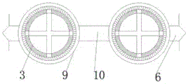
In the figure: the device comprises a box body 1, a baffle plate 2, a cloth filtering barrel 3, an air inlet pipe 4, an air blowing assembly 5, a cleaning assembly 6, a servo motor 7, a threaded rod 8, a brush barrel 9, a connecting block 10, a metal pipe 11, a punched mesh barrel 12, a turbofan 13, a spiral blade 14, an air suction pump 15, a pressurizing box 16, an electromagnetic valve 17, a vibration assembly 18, a vibration motor 19 and a funnel 20.
Detailed Description
The technical solutions in the embodiments of the present invention will be described clearly and completely with reference to the accompanying drawings in the embodiments of the present invention, and it is obvious that the described embodiments are only some embodiments of the present invention, not all embodiments.
Referring to fig. 1-3, the powder cleaning mechanism of the industrial dust collector comprises a box body 1, a baffle 2 is fixed on the inner wall of the box body 1, four symmetrically distributed mounting ports are arranged on the top of the baffle 2, a filter cloth cylinder 3 is fixed on the inner wall of the mounting ports through bolts, an air inlet is arranged on one side of the box body 1 and positioned on the upper side of the baffle 2, an air inlet pipe 4 is fixed on the inner wall of the air inlet, an air outlet is arranged on the bottom of the air inlet pipe 4 and positioned on the upper side of the filter cloth cylinder 3, an air blowing assembly 5 is fixed on the inner wall of the air outlet, the air blowing assembly 5 comprises a metal pipe 11, a spiral blade 14, a scroll 13 and a punching mesh cylinder 12, the punching mesh cylinder 12 is fixed on the inner wall of the mounting groove, one end of the spiral blade 14 is fixed on one side of the scroll 13, the spiral blade 14 forms a rotating fit with the inner, the blowing assembly 5 extends into the filter cloth cylinder 3, and drives the turbofan 13 to rotate and further drives the helical blade 14 to rotate when gas is subjected to back blowing, so that the pressure of the gas is higher during back blowing, and the gas is uniformly sprayed out by the punching screen cylinder 12, so that the dust filtering efficiency of the filter cloth cylinder 3 is improved;
the outer wall of the filter cloth cylinder 3 is provided with a cleaning component 6, the cleaning component 6 comprises a servo motor 7, a threaded rod 8, a brush cylinder 9 and a connecting block 10, the connecting block 10 is provided with a threaded hole, the inner wall of the threaded hole is in threaded fit with the threaded rod 8, an output shaft of the servo motor 7 is fixed at the top of the threaded rod 8 through a coupler, two sides of the brush barrel 9 are fixed at one end of the connecting block 10, the brush cylinder 9 and the filter cloth cylinder 3 form a sliding fit, the inner walls of the two sides of the box body 1 are provided with sliding chutes, the inner walls of the sliding chutes and the connecting blocks 10 form a sliding fit, the servo motor 7 is utilized to drive the threaded rod 8 to rotate through the servo motor 7, the threaded rod 8, the brush barrel 9 and the connecting block 10 which are arranged on the cleaning component 6, further driving the brush cylinder 9 to move up and down repeatedly, cleaning the dust and dirt condensed on the surface of the filter cloth cylinder 3, improving the filtering efficiency of the filter cloth cylinder 3 and further improving the working efficiency of the dust remover;
the bottom of the box body 1 is provided with a vibration component 18, the vibration component 18 comprises a funnel 20 and a vibration motor 19, the inner walls of two sides of the box body 1 are positioned at the lower side of the sliding groove and are provided with fixed grooves, the funnel 20 and the inner wall of the fixed groove form sliding fit, the bottom of the vibration motor 19 is fixed at the inner wall of the bottom of the fixed groove, the top of the vibration motor 19 is fixed at the bottom of the funnel 20, the top of the box body 1 is provided with an air outlet hole, the inner wall of the air outlet hole is connected with an air suction pump 15 through a pipe, the bottom of the box body 1 is provided with a discharge port, the inner wall of the discharge port is fixed with a discharge valve, the outer wall of the top of the box body 1 is fixed with a pressurizing box 16, one side of the pressurizing box 16 is provided with a mounting hole, the other side of the pressurizing box 16 is provided with a fixed hole, the fixed hole is connected with the air outlet end of the air suction pump 15 through a hose, the inner wall of the mounting hole is connected with an electromagnetic valve 17 through a connecting pipe, one end of the electromagnetic valve 17 is connected with a 4 through a mounting pipe, the inner wall of the metal pipe 11 is fixed with a cross frame which is symmetrically distributed, and both ends of the helical blade 14 are rotatably connected to the center of the cross through bearings.
The working principle is as follows: the air blowing assembly 5 extends into the filter cloth cylinder 3 through the metal pipe 11, the spiral blade 14, the turbofan 13 and the punching screen cylinder 12 which are arranged on the air blowing assembly 5, the turbofan 13 is driven to rotate during back blowing of air so as to drive the spiral blade 14 to rotate, the pressure of the air during back blowing is higher, the punching screen cylinder 12 is used for uniformly spraying, and the dust filtering efficiency of the filter cloth cylinder 3 is improved; through the servo motor 7, the threaded rod 8, the brush barrel 9 and the connecting block 10 which are arranged on the cleaning component 6, the servo motor 7 is utilized to drive the threaded rod 8 to rotate, so that the brush barrel 9 is driven to move up and down repeatedly, dust and dirt condensed on the surface of the filter cloth barrel 3 can be cleaned, the filtering efficiency of the filter cloth barrel 3 is improved, and the working efficiency of the dust remover is further improved; through the funnel 20 and the vibrating motor 19 that vibrating assembly 18 set up, can utilize the vibration to improve the speed of unloading, avoid the feed opening to block up.
In the description of the present invention, it is to be understood that the terms "center", "longitudinal", "lateral", "length", "width", "thickness", "upper", "lower", "front", "rear", "left", "right", "vertical", "horizontal", "top", "bottom", "inner", "outer", "clockwise", "counterclockwise", and the like indicate orientations or positional relationships based on the orientations or positional relationships shown in the drawings, and are only for convenience of description and to simplify the description, but do not indicate or imply that the device or element referred to must have a particular orientation, be constructed and operated in a particular orientation, and therefore should not be construed as limiting the present invention.
Furthermore, the terms "first", "second" and "first" are used for descriptive purposes only and are not to be construed as indicating or implying relative importance or implicitly indicating the number of technical features indicated. Thus, a feature defined as "first" or "second" may explicitly or implicitly include one or more of that feature. In the description of the present invention, "a plurality" means two or more unless specifically limited otherwise.
The above, only be the concrete implementation of the preferred embodiment of the present invention, but the protection scope of the present invention is not limited thereto, and any person skilled in the art is in the technical scope of the present invention, according to the technical solution of the present invention and the utility model, the concept of which is equivalent to replace or change, should be covered within the protection scope of the present invention.
Claims (6)
1. Clear powder mechanism of industrial dust remover, including box (1), its characterized in that, box (1) inner wall is fixed with baffle (2), and baffle (2) top is opened there are four symmetric distribution's installing port, and the installing port inner wall has filter cloth section of thick bamboo (3) through the bolt fastening, box (1) one side is located baffle (2) upside and is opened there is the air inlet, and the air inlet inner wall is fixed with intake pipe (4), intake pipe (4) bottom is located filter cloth section of thick bamboo (3) upside and is opened there is the gas outlet, and the gas outlet inner wall is fixed with the subassembly of blowing (5), the subassembly of blowing (5) includes tubular metal resonator (11), helical blade (14), turbofan (13) and the net section of thick bamboo that punches a hole (12), and tubular metal resonator (11) are opened there is the mounting groove, the net section of thick bamboo that punches a hole (12) are fixed at the mounting groove inner wall, helical blade (14) one end is fixed in turbofan (13) one side, and helical blade (14) and tubular metal resonator (11) inner wall form normal running fit, filter cloth section of thick bamboo (3) outer wall is equipped with cleans subassembly (6), and cleans subassembly (6) including servo motor (7), threaded rod (8), brush section of thick bamboo (9) and connecting block (10), threaded hole is opened in connecting block (10), and threaded hole inner wall and threaded rod (8) form the spiro union cooperation, the output shaft of servo motor (7) passes through the shaft coupling to be fixed at threaded rod (8) top, brush section of thick bamboo (9) both sides are all fixed in connecting block (10) one end, and brush section of thick bamboo (9) and filter cloth section of thick bamboo (3) form sliding fit, box (1) both sides inner wall is opened there is the spout, and spout inner wall and connecting block (10) form sliding fit.
2. The dust removing mechanism of the industrial dust collector as claimed in claim 1, wherein the bottom of the box body (1) is provided with a vibration component (18), the vibration component (18) comprises a funnel (20) and a vibration motor (19), the inner walls of two sides of the box body (1) are positioned at the lower side of the sliding groove and are provided with fixing grooves, the funnel (20) is in sliding fit with the inner walls of the fixing grooves, the bottom of the vibration motor (19) is fixed on the inner walls of the bottom of the fixing groove, and the top of the vibration motor (19) is fixed on the bottom of the funnel (20).
3. The powder cleaning mechanism of the industrial dust collector as claimed in claim 1, wherein the top of the box body (1) is provided with an air outlet, the inner wall of the air outlet is connected with a suction pump (15) through a guide pipe, the bottom of the box body (1) is provided with a discharge port, and the inner wall of the discharge port is fixed with a discharge valve.
4. The powder cleaning mechanism of the industrial dust collector as claimed in claim 3, wherein a pressure box (16) is fixed on the outer wall of the top of the box body (1), a mounting hole is formed on one side of the pressure box (16), a fixing hole is formed on the other side of the pressure box (16), and the fixing hole is connected with the air outlet end of the air suction pump (15) through a hose.
5. The dust removing mechanism of the industrial dust collector as claimed in claim 4, wherein the inner wall of the mounting hole is connected with an electromagnetic valve (17) through a connecting pipe, and one end of the electromagnetic valve (17) is connected with the air inlet pipe (4) through a mounting pipe.
6. The dust removing mechanism of the industrial dust collector as claimed in claim 1, wherein the inner wall of the metal tube (11) is fixed with a cross symmetrically distributed, and two ends of the helical blade (14) are rotatably connected with the center of the cross through a bearing.
Priority Applications (1)
| Application Number | Priority Date | Filing Date | Title |
|---|---|---|---|
| CN202023154845.6U CN214182234U (en) | 2020-12-24 | 2020-12-24 | Powder cleaning mechanism of industrial dust collector |
Applications Claiming Priority (1)
| Application Number | Priority Date | Filing Date | Title |
|---|---|---|---|
| CN202023154845.6U CN214182234U (en) | 2020-12-24 | 2020-12-24 | Powder cleaning mechanism of industrial dust collector |
Publications (1)
| Publication Number | Publication Date |
|---|---|
| CN214182234U true CN214182234U (en) | 2021-09-14 |
Family
ID=77656252
Family Applications (1)
| Application Number | Title | Priority Date | Filing Date |
|---|---|---|---|
| CN202023154845.6U Active CN214182234U (en) | 2020-12-24 | 2020-12-24 | Powder cleaning mechanism of industrial dust collector |
Country Status (1)
| Country | Link |
|---|---|
| CN (1) | CN214182234U (en) |
Cited By (1)
| Publication number | Priority date | Publication date | Assignee | Title |
|---|---|---|---|---|
| CN116212533A (en) * | 2023-05-08 | 2023-06-06 | 江苏丰鑫源环保集团有限公司 | Automatic cleaning type dust removing filter bag |
-
2020
- 2020-12-24 CN CN202023154845.6U patent/CN214182234U/en active Active
Cited By (1)
| Publication number | Priority date | Publication date | Assignee | Title |
|---|---|---|---|---|
| CN116212533A (en) * | 2023-05-08 | 2023-06-06 | 江苏丰鑫源环保集团有限公司 | Automatic cleaning type dust removing filter bag |
Similar Documents
| Publication | Publication Date | Title |
|---|---|---|
| CN205598817U (en) | Dust removal filter equipment with a rotatory section of thick bamboo and automatic deashing function of straining | |
| CN214182234U (en) | Powder cleaning mechanism of industrial dust collector | |
| CN112387024A (en) | A dust collecting equipment for weaving factory | |
| CN217188413U (en) | Air filter cleaning machine | |
| CN108079695A (en) | A kind of reverse dust-extraction unit | |
| CN212548704U (en) | Pulse dust collector for feed production | |
| CN215388220U (en) | Bag type pulse dust collector capable of easily cleaning dust | |
| CN109108259B (en) | Foundry goods processing is with shakeout device convenient to even feeding | |
| CN215026989U (en) | Device for improving dust removal efficiency of bag-type dust remover | |
| CN113856347A (en) | Novel energy-efficient dust exhausting fan | |
| CN213192877U (en) | A diffusion formula dust remover for clay sand is handled | |
| CN210728979U (en) | Environment-friendly filter drum dust remover | |
| CN212068020U (en) | Industrial fan dust collector | |
| CN113662473A (en) | All-weather uninterrupted dust collector | |
| CN212071643U (en) | Dust collector of shot blasting rust remover | |
| CN112316599A (en) | Efficient air compressor machine air supply system | |
| CN219701386U (en) | Double-inlet turbulence bag type dust collector | |
| CN220090809U (en) | Anti-blocking dust collection device | |
| CN215137889U (en) | Sack cleaner for ceramic manufacture | |
| CN219227978U (en) | Dust collector is used in circuit board production | |
| CN218458978U (en) | Strong effect cartridge filter | |
| CN219672813U (en) | Anti-blocking air inlet filtering structure | |
| CN217950685U (en) | Screw air compressor with easily cleaned air storage tank | |
| CN219441079U (en) | Self-cleaning type air suction dust remover | |
| CN114810588B (en) | Energy-saving electric vortex air conditioner compressor for new energy electric automobile |
Legal Events
| Date | Code | Title | Description |
|---|---|---|---|
| GR01 | Patent grant | ||
| GR01 | Patent grant |