CN215328221U - Improved laser quenching machining head - Google Patents
Improved laser quenching machining head Download PDFInfo
- Publication number
- CN215328221U CN215328221U CN202121665704.2U CN202121665704U CN215328221U CN 215328221 U CN215328221 U CN 215328221U CN 202121665704 U CN202121665704 U CN 202121665704U CN 215328221 U CN215328221 U CN 215328221U
- Authority
- CN
- China
- Prior art keywords
- machining head
- laser
- connecting plate
- laser beam
- straight section
- Prior art date
- Legal status (The legal status is an assumption and is not a legal conclusion. Google has not performed a legal analysis and makes no representation as to the accuracy of the status listed.)
- Active
Links
Images

Abstract
The utility model discloses an improved laser quenching machining head which comprises a laser machining head, an optical fiber interface and a workpiece, wherein the left side of the laser machining head is connected with the optical fiber interface, the workpiece is positioned below the laser machining head, the laser machining head comprises a straight section and an inclined section, a connecting plate is connected between the top of the right end of the straight section and the side wall in a sliding manner, a bifocal focusing lens is installed on one side, close to the optical fiber interface, of the connecting plate, a connecting column is hinged to the top of the side wall, far away from the bifocal focusing lens, of one side of the connecting plate, a threaded rod is screwed on the right side wall of the laser machining head, and one end, extending into the inner cavity of the laser machining head, of the threaded rod is rotatably connected with the connecting column.
Description
Technical Field
The utility model relates to the technical field of quenching machining heads, in particular to an improved laser quenching machining head.
Background
The laser quenching is a quenching technology which utilizes laser to heat the surface of a material to be above a phase change point, austenite is converted into martensite along with the self cooling of the material, so that the surface of the material is hardened. In recent years, the surface strengthening of parts such as molds and gears has been widely used.
The laser quenching tooth surface is adopted, the heating and cooling speed is high, the process period is short, no external quenching medium is needed, and the laser quenching tooth surface has the unique advantages of small workpiece deformation, clean working environment, no need of finish machining such as gear grinding and the like after treatment, no limitation of the size of the treated gear by the size of heat treatment equipment and the like.
The laser quenching has high power density and high cooling speed, does not need cooling media such as water or oil, and is a clean and rapid quenching process. Compared with the induction quenching, flame quenching and carburizing quenching processes, the laser quenching has the advantages of uniform hardening layer, high hardness (generally 1-3HRC higher than that of the induction quenching), small workpiece deformation, easy control of the depth of a heating layer and a heating track, easy realization of automation, no need of designing corresponding induction coils according to different part sizes like the induction quenching, no need of limitation of the size of a hearth during chemical heat treatment such as carburizing and quenching and the like for processing large parts, and thus the traditional processes such as the induction quenching, the chemical heat treatment and the like are gradually replaced in a plurality of industrial fields. In particular, the deformation of the workpiece before and after laser quenching is almost negligible, so that the method is particularly suitable for the surface treatment of parts with high precision requirements.
The position of a reflector in the existing laser quenching processing head is relatively fixed, so that the reflector is inconvenient to adjust, and a focus formed on the surface of a workpiece in the quenching process cannot be moved timely.
SUMMERY OF THE UTILITY MODEL
The present invention aims to provide an improved laser hardening machining head to solve the problems set forth in the background art described above.
In order to achieve the purpose, the utility model provides the following technical scheme: the utility model provides a follow-on laser quenching processing head, includes laser beam machining head, fiber interface and work piece, laser beam machining head's left side is connected with fiber interface, the work piece is located laser beam machining head's below, laser beam machining head is including straight section and oblique section, sliding connection has the connecting plate between the right-hand member top of straight section and the lateral wall, the bifocal focusing mirror is installed to one side that fiber interface is pressed close to the connecting plate, the lateral wall top that the connecting plate kept away from one side of bifocal focusing mirror articulates there is the spliced pole, laser beam machining head's right side wall spiro union has the threaded rod, the threaded rod stretches into the one end of laser inner chamber and is connected with the spliced pole looks rotation.
Preferably, the focal lengths of the two focal points of the bifocal focusing lens are the same.
Preferably, a first T-shaped sliding groove is formed in the top of the inner cavity of the straight section of the laser processing head, a first T-shaped block is connected to the inner cavity of the first T-shaped sliding groove in a sliding mode, a second T-shaped sliding groove is formed in the right side wall of the inner cavity of the straight section of the laser processing head, the second T-shaped sliding groove is located below the threaded rod, a second T-shaped block is connected to the inner cavity of the second T-shaped sliding groove in a sliding mode, and the second T-shaped block and the first T-shaped block are hinged to the two ends of the connecting plate respectively.
Preferably, the front end of the inner cavity of the straight section is provided with a collimating mirror.
Preferably, the included angle between the straight section and the inclined section of the laser processing head is 30-45 degrees.
Compared with the prior art, the utility model has the beneficial effects that:
the improved laser quenching processing head corrects the divergent light beam into a parallel light beam by the laser beam through the collimating lens, the laser beam forms two light spots on the surface of a workpiece after passing through the bifocal focusing lens, a right-angle surface laser quenching process can be carried out, meanwhile, the threaded rod, the connecting plate, the first T-shaped block and the second T-shaped block form an angle adjusting structure, the installation angle of the bifocal focusing lens is adjusted by the angle adjusting structure, the connecting plate is driven by rotating the threaded rod to move along the inner cavity side wall of the laser processing head, the first T-shaped block and the second T-shaped block in the inner cavity side wall of the laser processing head limit the two sides of the connecting plate, so that the possibility that the connecting plate is separated from the laser processing head 1 is reduced, and the threaded rod is connected above the connecting plate, therefore, the moving directions of the two sides of the connecting plate are different in the moving process of the threaded rod, and the angle of the connecting plate can be adjusted in real time, therefore, the angle of the bifocal focusing lens is adjusted, the processing range of the laser processing head is enlarged, and the quenching precision is improved.
Drawings
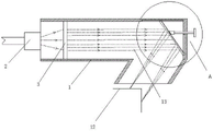
FIG. 1 is a front view in cross section of the overall structure of the present invention;
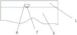
FIG. 2 is an enlarged view of part A of the present invention;
figure 3 is a cross-sectional side view of a laser machining head of the present invention;
in the figure, 1, a laser processing head; 2. an optical fiber interface; 3. a collimating mirror; 4. a connecting plate; 5. a bifocal focusing lens; 6. a first T-shaped chute; 7. a first T-shaped block; 8. a second T-shaped chute; 9. a second T-shaped block; 10. connecting columns; 11. a threaded rod; 12. a workpiece; 13. a laser beam.
Detailed Description
The technical solutions in the embodiments of the present invention will be clearly and completely described below with reference to the drawings in the embodiments of the present invention, and it is obvious that the described embodiments are only a part of the embodiments of the present invention, and not all of the embodiments. All other embodiments, which can be derived by a person skilled in the art from the embodiments given herein without making any creative effort, shall fall within the protection scope of the present invention.
Referring to fig. 1-3, an embodiment of the present invention is provided.
As shown in fig. 1-3, an improved laser quenching machining head, including laser machining head 1, optical fiber interface 2 and work piece 12, the left side of laser machining head 1 is connected with optical fiber interface 2, work piece 12 is located the below of laser machining head 1, laser machining head 1 includes straight section and oblique section, sliding connection has connecting plate 4 between the right-hand member top of straight section and the lateral wall, double-focus focusing mirror 5 is installed to one side that optical fiber interface 2 is pressed close to connecting plate 4, the lateral wall top that connecting plate 4 kept away from one side of double-focus focusing mirror 5 articulates there is spliced pole 10, the right side wall spiro union of laser machining head 1 has threaded rod 11, threaded rod 11 stretches into the one end of laser machining head 1 inner chamber and is connected with spliced pole 10 mutually and rotate.
It can be understood that the bifocal focusing lens 5 and the connecting plate 4 can be adhered by glue, or the connecting plate 4 is provided with a slot, and the bifocal focusing lens 5 is inserted into the slot and fixed.
Specifically, as shown in fig. 1, the focal lengths of the two focal points of the bifocal focusing lens 5 are the same, so that two circular light spots or two square light spots can be formed, thereby facilitating the quenching process at the right angle of the workpiece 12.
Further, as shown in fig. 2-3, a first T-shaped chute 6 is formed in the top of the inner cavity of the straight section of the laser processing head 1, a first T-shaped block 7 is slidably connected to the inner cavity of the first T-shaped chute 6, a second T-shaped chute 8 is formed in the right side wall of the inner cavity of the straight section of the laser processing head 1, the second T-shaped chute 8 is located below the threaded rod 11, a second T-shaped block 9 is slidably connected to the inner cavity of the second T-shaped chute 8, the second T-shaped block 9 and the first T-shaped block 7 are respectively hinged to two ends of the connecting plate 4, so that the sliding of two ends of the connecting plate 4 is facilitated, the angle of the bifocal focusing mirror 5 is adjusted, thereby quenching processing can be performed on different positions of the surface of the workpiece 12 with a right angle, and the quenching processing range of the device is expanded.
Further, the collimating mirror 3 is installed at the front end of the inner cavity of the straight section, and the collimating mirror 3 can change the laser beam 13 emitted by the optical fiber interface 2 into a parallel beam, so that the beam can be regularly irradiated onto the bifocal focusing mirror 5, and further the processing of the workpiece 12 is facilitated.
Furthermore, the included angle between the straight section and the inclined section of the laser processing head 1 is 30-45 degrees, so that the laser beam 13 can conveniently irradiate and quench the surface of the workpiece 12, and meanwhile, the focus generated by the light beam emitted by the double-focus focusing lens 5 can be ensured to accurately pass through the laser processing head 1 and be formed on the surface of the workpiece 12, and the accuracy of laser quenching processing is ensured.
The working principle is as follows: laser beams 13 emitted by an optical fiber interface 2 are output to the inside of a laser processing head 1, the laser beams 13 firstly reach a collimating mirror 3, the collimating mirror 3 converts astigmatism into parallel beams, the parallel beams are reflected after reaching a bifocal focusing mirror 5, the bifocal focusing mirror 5 consists of two focusing mirrors, the focal lengths of the two focusing mirrors are the same, only the positions of focal points are different, the focal positions of the focusing mirrors have certain distances, thus two round or square light spots can be formed and reach the surface of a workpiece 12, the two sides of the right-angle workpiece 12 are quenched in the direction vertical to the paper surface at a certain speed by adopting proper laser power and a laser head, when the position of the laser beams 13 irradiating the surface of the workpiece 12 does not reach a specified quenching area, a threaded rod 11 is manually adjusted, the rotating threaded rod 11 moves towards the left side and the right side of the laser processing head 1, the moving threaded rod 11 drives a connecting plate 4 to move along the inner cavity side wall of the laser processing head 1, the first T-shaped block 7 and the second T-shaped block 9 in the side wall of the inner cavity of the laser processing head 1 limit the two sides of the connecting plate 4, so that the possibility of separation of the connecting plate 4 and the laser processing head 1 is reduced, and the connecting plate 4 is fixedly connected with the bifocal focusing lens 5, so that the moving trend of the bifocal focusing lens 5 is the same as that of the connecting plate 4, the angle of the bifocal focusing lens 5 is adjusted, and the workpiece 12 is accurately quenched.
It will be evident to those skilled in the art that the utility model is not limited to the details of the foregoing illustrative embodiments, and that the present invention may be embodied in other specific forms without departing from the spirit or essential attributes thereof. The present embodiments are therefore to be considered in all respects as illustrative and not restrictive, the scope of the utility model being indicated by the appended claims rather than by the foregoing description, and all changes which come within the meaning and range of equivalency of the claims are therefore intended to be embraced therein. Any reference sign in a claim should not be construed as limiting the claim concerned.
Claims (5)
1. The utility model provides an improved generation laser hardening processing head, includes laser beam machining head (1), optic fibre interface (2) and work piece (12), its characterized in that: the left side of laser beam machining head (1) is connected with optical fiber interface (2), work piece (12) are located the below of laser beam machining head (1), laser beam machining head (1) is including straight section and oblique section, sliding connection has connecting plate (4) between the right-hand member top of straight section and the lateral wall, double-focal focusing mirror (5) are installed to one side that optical fiber interface (2) are pressed close to in connecting plate (4), the lateral wall top of one side of double-focal focusing mirror (5) is kept away from in connecting plate (4) articulates there is spliced pole (10), the right side wall spiro union of laser beam machining head (1) has threaded rod (11), threaded rod (11) stretch into the one end of laser beam machining head (1) inner chamber and are rotated mutually with spliced pole (10) and are connected.
2. An improved laser quench machining head as claimed in claim 1 wherein: the focal lengths of the two focuses of the bifocal focusing lens (5) are the same.
3. An improved laser quench machining head as claimed in claim 1 wherein: first T shape spout (6) have been seted up at the inner chamber top of the straight section of laser beam machining head (1), the inner chamber sliding connection of first T shape spout (6) has first T shape piece (7), second T shape spout (8) have been seted up to the inner chamber right side wall of the straight section of laser beam machining head (1), and second T shape spout (8) are located threaded rod (11) below, the inner chamber sliding connection of second T shape spout (8) has second T shape piece (9), second T shape piece (9) and first T shape piece (7) are articulated mutually with the both ends of connecting plate (4) respectively.
4. An improved laser quench machining head as claimed in claim 1 wherein: and the front end of the inner cavity of the straight section is provided with a collimating mirror (3).
5. An improved laser quench machining head as claimed in claim 1 wherein: the included angle between the straight section and the inclined section of the laser processing head (1) is 30-45 degrees.
Priority Applications (1)
| Application Number | Priority Date | Filing Date | Title |
|---|---|---|---|
| CN202121665704.2U CN215328221U (en) | 2021-07-21 | 2021-07-21 | Improved laser quenching machining head |
Applications Claiming Priority (1)
| Application Number | Priority Date | Filing Date | Title |
|---|---|---|---|
| CN202121665704.2U CN215328221U (en) | 2021-07-21 | 2021-07-21 | Improved laser quenching machining head |
Publications (1)
| Publication Number | Publication Date |
|---|---|
| CN215328221U true CN215328221U (en) | 2021-12-28 |
Family
ID=79569161
Family Applications (1)
| Application Number | Title | Priority Date | Filing Date |
|---|---|---|---|
| CN202121665704.2U Active CN215328221U (en) | 2021-07-21 | 2021-07-21 | Improved laser quenching machining head |
Country Status (1)
| Country | Link |
|---|---|
| CN (1) | CN215328221U (en) |
-
2021
- 2021-07-21 CN CN202121665704.2U patent/CN215328221U/en active Active
Similar Documents
| Publication | Publication Date | Title |
|---|---|---|
| US10106864B2 (en) | Method and apparatus for laser quenching | |
| CN1029597C (en) | Target domain profiling of target optical surfaces using excimer laser photoablation | |
| US4250372A (en) | Process and apparatus for the heat treatment by high energy beams of surfaces of steel products | |
| CN103290176B (en) | A kind of multi irradiation laser-quenching method and device | |
| CN206241474U (en) | A kind of laser processing device | |
| CN109848566B (en) | Method and device for grinding and polishing parts and dies by mixed laser | |
| CN109593919B (en) | Bearing surface laser quenching device and method based on distributed three-dimensional light beam scanning | |
| CN108816964B (en) | Random laser cleaning device and method | |
| CN103878495A (en) | Method and device for precisely machining deep groove and deep hole by varifocal lasers | |
| CN215328221U (en) | Improved laser quenching machining head | |
| CN202877731U (en) | Laser texturing processing device with focusing light dot controlled to be deflected | |
| CN102380706A (en) | Fiber laser texturing system | |
| CN104526157A (en) | Rotating beam preheating laser shock wave micro-texturing machining device and method | |
| CN104551408A (en) | System and method for multi-beam synthesizing and focusing type roll surface texturing laser processing | |
| JP2006168260A (en) | Manufacturing method of mold for molding light guide plate, mold for molding light guide plate, and light guide plate | |
| CN204248222U (en) | A kind of three axle dynamic focusing laser mark printing devices | |
| CN104294011A (en) | Inner bore laser quenching head and quenching method | |
| CN108559819A (en) | The laser transformation hardening method and processing unit (plant) of variable pitch/yaw bearing lasso raceway | |
| CN204824967U (en) | Laser hardening processing head | |
| CN104611536B (en) | Method for heat treatment of allow iron plate nut | |
| CN114231728A (en) | Device and method for strengthening curved surface part by laser impact on surface layer | |
| EP0062517A1 (en) | Heat treatment of workpiece by laser | |
| CN103667607B (en) | A kind of laser-quenching method based on scanning galvanometer and device | |
| CN2264189Y (en) | Special equipment of using laser for surface quenching to corrugated roller | |
| CN204417554U (en) | Allow iron plate capotasto thermal treatment unit |
Legal Events
| Date | Code | Title | Description |
|---|---|---|---|
| GR01 | Patent grant | ||
| GR01 | Patent grant |