CN215319979U - Quick replacement die device for plastic die machining - Google Patents
Quick replacement die device for plastic die machining Download PDFInfo
- Publication number
- CN215319979U CN215319979U CN202121644260.4U CN202121644260U CN215319979U CN 215319979 U CN215319979 U CN 215319979U CN 202121644260 U CN202121644260 U CN 202121644260U CN 215319979 U CN215319979 U CN 215319979U
- Authority
- CN
- China
- Prior art keywords
- fixedly connected
- disc
- plastic
- die
- mounting
- Prior art date
- Legal status (The legal status is an assumption and is not a legal conclusion. Google has not performed a legal analysis and makes no representation as to the accuracy of the status listed.)
- Active
Links
Images


Abstract
The utility model provides a quick die replacing device for plastic die machining, and relates to the technical field of plastic die machining. This quick replacement die set is used in processing of plastic mold, comprises a workbench, workstation bottom end fixedly connected with supporting leg, the workstation top is provided with the spout, the inside swing joint of spout has the threaded rod, threaded rod surface fixed connection has the action wheel. This quick replacement die set is used in processing of plastic mold, through the cylinder, a slide rail, the disc, mounting disc and fastening bolt, the user twists the mould that will be originally and pulls down from the mounting disc with mounting bolt, later the mould that will change passes through mounting bolt and installs on the mounting disc, comparatively convenient and fast, through the spout, the threaded rod, the action wheel, the hold-in range, from the driving wheel, servo motor, the slider, splint, the cutting, spring and lug, it is fixed to further centre gripping of mould, centre gripping fastening nature has been improved, the condition that the mould takes place to become flexible in the course of working has been avoided.
Description
Technical Field
The utility model relates to the technical field of plastic die machining, in particular to a quick die replacing device for plastic die machining.
Background
The plastic mold is a mold for plastic molding, can be divided into an injection mold, a compression mold and a transmission mold according to a molding principle, and is mainly used for realizing the processing of the appearance of the plastic mold through the change of the physical state of a molded material so as to process various plastic molds, and the mold needs to be frequently replaced in the processing process, so that the quick mold replacing device for plastic mold processing is widely used in the plastic mold production industry.
Current quick replacement die set for plastic mold processing often only fixes and is equipped with single mould, to the mould goods of difference, and the user of service needs to change the mould and makes, and is comparatively troublesome when changing the mould, causes work efficiency to reduce easily, and is relatively poor to the centre gripping fastening nature of mould, leads to the mould to take place not hard up in the course of working, influences the shaping effect, is not convenient for use widely.
Therefore, it is necessary to provide a quick-change mold device for plastic molding to solve the above problems.
SUMMERY OF THE UTILITY MODEL
Technical problem to be solved
Aiming at the defects of the prior art, the utility model provides a quick-change die device for plastic die processing, which solves the problems that the existing quick-change die device for plastic die processing provided in the background art is troublesome in die replacement and poor in clamping and fastening performance on a die.
(II) technical scheme
In order to achieve the purpose, the utility model is realized by the following technical scheme: a quick-replacement die device for plastic die machining comprises a workbench, wherein a supporting leg is fixedly connected to the bottom end of the workbench, a chute is arranged at the top end of the workbench, a threaded rod is movably connected inside the chute, an active wheel is fixedly connected to the outer surface of the threaded rod, a synchronous belt is sleeved on the outer surface of the active wheel, a driven wheel is movably connected to one side, far away from the active wheel, of the inner wall of the synchronous belt, a servo motor is fixedly connected to the outer surface of the active wheel, a sliding block is sleeved on the outer surface of the threaded rod, a clamping plate is fixedly connected to the top end of the sliding block, an inserting strip is movably connected inside the clamping plate, a spring is sleeved on the outer surface of the inserting strip, a convex block is fixedly connected to the outer surface of the inserting strip, a mounting plate is fixedly connected to one side, located on the chute, of the top end of the mounting plate, a cylinder is fixedly connected to the top end of the mounting plate, and a sliding rail is connected to one side, located on the cylinder, the piston rod is movably connected to the bottom end of the air cylinder, a disc is fixedly connected to the bottom end of the piston rod, an installation disc is fixedly connected to the bottom end of the disc, and an installation bolt penetrates through the installation disc.
Preferably, the servo motor and the cylinder are electrically connected with an external power supply.
Preferably, the number of the threaded rods is two, the two threaded rods are respectively connected with the driving wheel and the driven wheel, and the thread directions of the outer surfaces of the threaded rods are opposite.
Preferably, the driving wheel is connected with the servo motor through a bearing.
Preferably, the slide rail is movably connected with the disc.
Preferably, a sliding hole is formed in the mounting disc, and the sliding hole is matched with the sliding rail.
(III) advantageous effects
The utility model provides a quick die replacing device for plastic die machining. The method has the following beneficial effects:
1. this quick replacement die set is used in processing of plastic mold, through the cylinder, a slide rail, the disc, mounting disc and fastening bolt, when needs processing polytype plastic mold, the user twists the mould that will be originally of mounting bolt and pulls down from the mounting disc, later the mould that will change passes through mounting bolt and installs on the mounting disc, it begins work to control the cylinder, its piston rod downstream drives disc and mounting disc and along slide rail downstream, be convenient for carry out the punching press preparation, and comparatively convenient and fast, comparatively troublesome problem when having solved the change mould.
2. This quick replacement die set is used in processing of plastic mold, through the spout, the threaded rod, the action wheel, the hold-in range, from the driving wheel, servo motor, the slider, splint, the cutting, spring and lug, servo motor passes through the bearing and drives the action wheel and rotate, drive simultaneously under the effect of hold-in range and rotate from the driving wheel, two threaded rods are synchronous at the spout internal rotation this moment, and then drive the slider and move on the threaded rod, under the drive of slider, two splint are synchronous to the inboard motion, carry out the centre gripping to the mould, when the size of mould is great, the user of service is to both sides pulling lug, the lug drives the spring and the cutting moves to the outside this moment, it is fixed to further centre gripping to the mould, centre gripping fastening nature has been improved, the not hard up condition of mould emergence in the course of working has been avoided, the relatively poor problem of centre gripping fastening nature to the mould has been solved.
Drawings
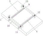
FIG. 1 is a schematic structural view of the present invention;
FIG. 2 is a schematic view of a worktable according to the present invention;
FIG. 3 is a schematic side view of the present invention;
FIG. 4 is a schematic top view of the present invention.
In the figure: 1. a work table; 2. supporting legs; 3. a chute; 4. a threaded rod; 5. a driving wheel; 6. a synchronous belt; 7. a driven wheel; 8. a servo motor; 9. a slider; 10. a splint; 11. cutting; 12. a spring; 13. a bump; 14. mounting a plate; 15. a cylinder; 16. a slide rail; 17. a piston rod; 18. a disc; 19. mounting a disc; 20. and (6) installing a bolt.
Detailed Description
The technical solutions in the embodiments of the present invention will be clearly and completely described below with reference to the drawings in the embodiments of the present invention, and it is obvious that the described embodiments are only a part of the embodiments of the present invention, and not all of the embodiments. All other embodiments, which can be derived by a person skilled in the art from the embodiments given herein without making any creative effort, shall fall within the protection scope of the present invention.
The embodiment of the utility model provides a quick die replacing device for plastic die processing, which comprises a workbench 1, wherein the bottom end of the workbench 1 is fixedly connected with a supporting leg 2, the top end of the workbench 1 is provided with a chute 3, the chute 3 is internally and movably connected with a threaded rod 4, the outer surface of the threaded rod 4 is fixedly connected with a driving wheel 5, the outer surface of the driving wheel 5 is sleeved with a synchronous belt 6, the inner wall of the synchronous belt 6 and one side far away from the driving wheel 5 are movably connected with a driven wheel 7, the outer surface of the driving wheel 5 is fixedly connected with a servo motor 8, the outer surface of the threaded rod 4 is sleeved with a sliding block 9, the top end of the sliding block 9 is fixedly connected with a clamping plate 10, the inner part of the clamping plate 10 is movably connected with an inserting strip 11, the outer surface of the inserting strip 11 is sleeved with a spring 12, the outer surface of the inserting strip 11 is fixedly connected with a lug 13, the servo motor 8 drives the driving wheel 5 to rotate through a bearing, and simultaneously drives the driven wheel 7 to rotate under the action of the synchronous belt 6, at the moment, the two threaded rods 4 synchronously rotate in the sliding grooves 3, so as to drive the sliding blocks 9 to move on the threaded rods 4, under the driving of the sliding blocks 9, the two clamping plates 10 synchronously move inwards to clamp the die, when the size of the die is larger, a user pulls the convex blocks 13 towards two sides, at the moment, the convex blocks 13 drive the springs 12 and the inserting strips 11 to move outwards, the die is further clamped and fixed, the clamping tightness is improved, and the condition that the die is loosened in the machining process is avoided, the top end of the workbench 1 and one side of the sliding grooves 3 are fixedly connected with a mounting plate 14, the top end of the mounting plate 14 is fixedly connected with an air cylinder 15, one side of the top end of the mounting plate 14, which is positioned on the air cylinder 15, is penetrated by a sliding rail 16, the bottom end of the air cylinder 15 is movably connected with a piston rod 17, the bottom end of the piston rod 17 is fixedly connected with a circular disc 18, the bottom end of the circular disc 18 is fixedly connected with a mounting disc 19, and a mounting bolt 20 is penetrated inside the mounting disc 19, when multiple types of plastic mold need to be processed, a user twists installation bolt 20 to detach the original mold from installation disc 19, then installs the replaced mold on installation disc 19 through installation bolt 20, controls cylinder 15 to start working, and moves piston rod 17 downwards and drives disc 18 and installation disc 19 to move downwards along slide rail 16, so that the punching manufacture is facilitated, and the operation is convenient and fast.
The working principle is as follows: when the die is used, an external power supply is switched on, when various types of plastic dies need to be processed, a user twists and drives the mounting bolt 20 to detach the original die from the mounting disc 19, then the replaced die is mounted on the mounting disc 19 through the mounting bolt 20, the control cylinder 15 starts to work, the piston rod 17 of the control cylinder moves downwards and drives the disc 18 and the mounting disc 19 to move downwards along the slide rail 16, the stamping manufacture is convenient, and the control cylinder is convenient and quick to use, the servo motor 8 drives the driving wheel 5 to rotate through the bearing, the driven wheel 7 is driven to rotate under the action of the synchronous belt 6, at the moment, the two threaded rods 4 synchronously rotate in the sliding grooves 3, the sliding blocks 9 are driven to rotate on the threaded rods 4, the two clamping plates 10 synchronously move inwards under the driving of the sliding blocks 9, the die is clamped, when the size of the die is large, the user pulls the convex blocks 13 towards two sides, at this moment, the convex block 13 drives the spring 12 and the inserting strip 11 to move outwards, the mold is further clamped and fixed, the clamping tightness is improved, and the condition that the mold is loosened in the machining process is avoided.
It is noted that, herein, relational terms such as first and second, and the like may be used solely to distinguish one entity or action from another entity or action without necessarily requiring or implying any actual such relationship or order between such entities or actions. Also, the terms "comprises," "comprising," or any other variation thereof, are intended to cover a non-exclusive inclusion, such that a process, method, article, or apparatus that comprises a list of elements does not include only those elements but may include other elements not expressly listed or inherent to such process, method, article, or apparatus. Without further limitation, an element defined by the phrase "comprising an … …" does not exclude the presence of other identical elements in a process, method, article, or apparatus that comprises the element.
Although embodiments of the present invention have been shown and described, it will be appreciated by those skilled in the art that changes, modifications, substitutions and alterations can be made in these embodiments without departing from the principles and spirit of the utility model, the scope of which is defined in the appended claims and their equivalents.
Claims (6)
1. The utility model provides a quick replacement mould device is used in processing of plastic mold, includes workstation (1), its characterized in that: the bottom end of the workbench (1) is fixedly connected with a supporting leg (2), the top end of the workbench (1) is provided with a chute (3), the inside of the chute (3) is movably connected with a threaded rod (4), the outer surface of the threaded rod (4) is fixedly connected with an action wheel (5), the outer surface of the action wheel (5) is sleeved with a synchronous belt (6), one side of the inner wall of the synchronous belt (6) far away from the action wheel (5) is movably connected with a driven wheel (7), the outer surface of the action wheel (5) is fixedly connected with a servo motor (8), the outer surface of the threaded rod (4) is sleeved with a sliding block (9), the top end of the sliding block (9) is fixedly connected with a clamping plate (10), the inside of the clamping plate (10) is movably connected with an inserting strip (11), the outer surface of the inserting strip (11) is sleeved with a spring (12), and the outer surface of the inserting strip (11) is fixedly connected with a convex block (13), workstation (1) top just is located one side fixedly connected with mounting panel (14) of spout (3), mounting panel (14) top fixedly connected with cylinder (15), one side that mounting panel (14) top just is located cylinder (15) has been crossed and has been had slide rail (16), cylinder (15) bottom swing joint has piston rod (17), piston rod (17) bottom fixedly connected with disc (18), disc (18) bottom fixedly connected with mounting disc (19), mounting disc (19) inside has been crossed and has been had been connected mounting bolt (20).
2. The quick change die apparatus for plastic molding according to claim 1, wherein: the servo motor (8) and the air cylinder (15) are electrically connected with an external power supply.
3. The quick change die apparatus for plastic molding according to claim 1, wherein: the two threaded rods (4) are respectively connected with the driving wheel (5) and the driven wheel (7), and the thread directions of the outer surfaces of the threaded rods (4) are opposite.
4. The quick change die apparatus for plastic molding according to claim 1, wherein: the driving wheel (5) is connected with the servo motor (8) through a bearing.
5. The quick change die apparatus for plastic molding according to claim 1, wherein: the slide rail (16) is movably connected with the disc (18).
6. The quick change die apparatus for plastic molding according to claim 1, wherein: and a sliding hole is formed in the mounting disc (19) and is matched with the sliding rail (16).
Priority Applications (1)
| Application Number | Priority Date | Filing Date | Title |
|---|---|---|---|
| CN202121644260.4U CN215319979U (en) | 2021-07-19 | 2021-07-19 | Quick replacement die device for plastic die machining |
Applications Claiming Priority (1)
| Application Number | Priority Date | Filing Date | Title |
|---|---|---|---|
| CN202121644260.4U CN215319979U (en) | 2021-07-19 | 2021-07-19 | Quick replacement die device for plastic die machining |
Publications (1)
| Publication Number | Publication Date |
|---|---|
| CN215319979U true CN215319979U (en) | 2021-12-28 |
Family
ID=79568478
Family Applications (1)
| Application Number | Title | Priority Date | Filing Date |
|---|---|---|---|
| CN202121644260.4U Active CN215319979U (en) | 2021-07-19 | 2021-07-19 | Quick replacement die device for plastic die machining |
Country Status (1)
| Country | Link |
|---|---|
| CN (1) | CN215319979U (en) |
-
2021
- 2021-07-19 CN CN202121644260.4U patent/CN215319979U/en active Active
Similar Documents
| Publication | Publication Date | Title |
|---|---|---|
| CN1799815A (en) | Full-automatic plastic suction forming machine | |
| CN211135145U (en) | Punching device for automatic machining of textile crankshafts | |
| CN215319979U (en) | Quick replacement die device for plastic die machining | |
| CN213917164U (en) | Rotary positioning fixture for mold machining | |
| CN213002211U (en) | Mechanical stamping device | |
| CN209015992U (en) | A kind of automatic assembling apparatus of breaker of plastic casing pedestal assembly | |
| CN209334587U (en) | A kind of flexible clamp | |
| CN219543472U (en) | Automatic cutting machine | |
| CN215703306U (en) | Assembled cutting and placing integrated machine | |
| CN218425109U (en) | Adjustable automatic punching device | |
| CN219766526U (en) | Multifunctional movable combined punching machine | |
| CN220426533U (en) | Stamping die for stamping metal products | |
| CN219253891U (en) | Pressure transition backing plate | |
| CN215657351U (en) | Movable press workbench | |
| CN213919332U (en) | Gear injection mold | |
| CN209550409U (en) | Based on mechanical devices mould punching formed punch driving structure | |
| CN215315277U (en) | Mould stamping device convenient to quick drawing of patterns | |
| CN219191264U (en) | Modified plastic production stretcher with clamping and adjusting functions | |
| CN212070510U (en) | Mould parts machining clamping device | |
| CN218693178U (en) | Adjustable stamping die | |
| CN214419543U (en) | Quick replacement structure for mold of blow molding machine | |
| CN217020893U (en) | Antifouling insulator drawing of patterns tilting mechanism | |
| CN216614717U (en) | Leather cutting equipment for producing automobile cushion sleeve | |
| CN210588299U (en) | Mold blank positioning device for processing automobile mold blank | |
| CN220278949U (en) | Die clamping mechanism with size adjusting structure |
Legal Events
| Date | Code | Title | Description |
|---|---|---|---|
| GR01 | Patent grant | ||
| GR01 | Patent grant |