CN215305627U - Driving device for cleaning mechanism of mop bucket - Google Patents
Driving device for cleaning mechanism of mop bucket Download PDFInfo
- Publication number
- CN215305627U CN215305627U CN202120369724.9U CN202120369724U CN215305627U CN 215305627 U CN215305627 U CN 215305627U CN 202120369724 U CN202120369724 U CN 202120369724U CN 215305627 U CN215305627 U CN 215305627U
- Authority
- CN
- China
- Prior art keywords
- gear
- mop
- cleaning mechanism
- cleaning
- driving
- Prior art date
- Legal status (The legal status is an assumption and is not a legal conclusion. Google has not performed a legal analysis and makes no representation as to the accuracy of the status listed.)
- Active
Links
Images


Landscapes
- Cleaning Implements For Floors, Carpets, Furniture, Walls, And The Like (AREA)
Abstract
The utility model discloses a driving device of a cleaning mechanism for a mop bucket, wherein the cleaning mechanism is used for cleaning a mop head of a mop arranged in the mop bucket, the driving device is used for controlling the operation and the stop of the cleaning mechanism, the mop bucket comprises a water storage area and a mop placing area, and the cleaning mechanism is arranged at the position, close to the mop placing area, of the water storage area; the driving device comprises a driving mechanism for driving the cleaning mechanism to operate and a control mechanism for controlling the driving mechanism to operate and stop; the mop drives the driving mechanism to operate from top to bottom. The mop cleaning machine has the advantages that the cleaning mechanism is driven by the driving device to clean and wring the mop, the mop is inserted for cleaning, and the mop is taken out for wringing, so that the problem of manual cleaning is solved, and the mop cleaning machine is simple and reasonable in structure, convenient to operate and use, good in cleaning effect and low in production cost, and the cleaning and wringing are alternately carried out; meanwhile, the automatic reset control mechanism is arranged, so that the device is more convenient.
Description
Technical Field
The utility model relates to the technical field of mop buckets, in particular to a driving device of a cleaning mechanism for a mop bucket.
Background
The flat mop is a cleaning tool for scrubbing the floor, which is very popular in recent years, and is widely used in households, small offices, commercial places and the like. Dull and stereotyped mop comprises mop pole, bottom plate and mop, and the bottom plate adopts dull and stereotyped design, and its advantage that has: (1) the stress area between the flat bottom plate and the ground is large, the stress is uniform, hairs and fine dust on the ground can be stuck, and the cleanliness of the mopping floor is improved; (2) compared with a circular bottom plate, the flat bottom plate can increase the mopping area and improve the mopping efficiency.
However, the flat mop has the following problems during use: before use, the wet mop needs to be manually squeezed, then the mop needs to be fixed above the flat mop for use, and after use, the mop needs to be detached from the flat mop for manual cleaning and squeezing, so that the working efficiency is low, and the hands are dirtied during cleaning and squeezing, and the requirements of the broad masses of consumers on cleanness and sanitation cannot be met.
SUMMERY OF THE UTILITY MODEL
Technical problem to be solved
The utility model aims to solve the technical problem of providing a driving device for a cleaning mechanism of a mop bucket, which is used for cleaning and wringing mop by driving the cleaning mechanism through the driving device, cleaning is carried out by inserting the mop, wringing is carried out by taking out the mop, the problem of manual cleaning is solved, and the driving device has the advantages of simple and reasonable structure, convenient operation and use, alternate cleaning and wringing, good cleaning effect and low production cost.
(II) technical scheme
The utility model solves the technical problem by adopting the scheme that the driving device is used for the cleaning mechanism of the mop bucket, the cleaning mechanism is used for cleaning the mop head of the mop arranged in the mop bucket, and the driving device is used for controlling the operation and the stop of the cleaning mechanism; the mop bucket comprises a water storage area and a mop placing area, and the cleaning mechanism is arranged at the position, close to the mop placing area, of the water storage area; the driving device comprises a driving mechanism for driving the cleaning mechanism to operate and a control mechanism for controlling the driving mechanism to operate and stop; the mop drives the driving mechanism to operate from top to bottom.
Specifically, the mop comprises a mop head and a mop handle, and when the mop head rotates to be parallel to the mop handle, the mop head can be placed into the mop bucket for cleaning and squeezing.
By adopting the scheme, the mop is cleaned and squeezed by the driving device driving the cleaning mechanism, the problem that hands can be dirtied when the mop is manually cleaned is solved, and the mop cleaning device is simple and reasonable in structure, simple and convenient to operate and good in manual cleaning effect.
Furthermore, the driving mechanism comprises a gear set, the gear set comprises a driving gear, a first gear in transmission connection with the driving gear, a one-way gear meshed with the first gear, and a second gear meshed with the one-way gear, wherein the driving gear is driven by the mop to operate, and the second gear is in transmission connection with the cleaning mechanism.
Furthermore, a fixing piece is arranged on the outer side of the one-way gear, and the fixing piece is provided with a tooth-shaped area matched with the one-way gear.
By adopting the scheme, the gear area is matched with the one-way gear, so that the one-way operation of the one-way gear can be ensured, and the mop can not rotate reversely when moving upwards, thereby ensuring that the cleaning mechanism can not be driven and the mop head can be squeezed to dry.
Furthermore, the one-way gear has a one-way gear rotating shaft, a poking tooth is arranged on the one-way gear rotating shaft, the poking tooth is meshed with a third gear, the third gear is connected with the control mechanism, and the control mechanism is used for controlling the operation and the stop of the third gear.
Preferably, a poking tooth is arranged on the one-way gear rotating shaft, the one-way gear rotates for a circle, and the poking tooth pokes the third gear once to enable the third gear to rotate for the distance of one tooth.
Preferably, the gear ring of the third gear is provided with 21 teeth, so that the one-way gear rotates 21 times, and the third gear rotates exactly once.
Preferably, the mop is inserted into the mop placing area from top to bottom until the mop placing area is completely inserted, the driving gear can be driven to rotate for 7 circles, then the one-way gear rotates for 7 circles, and the third gear is stirred to rotate for a distance of 7 teeth, so that the mop is inserted for 3 times, and the third gear just rotates for a circle.
Further, the control mechanism comprises an operating part and a reset part which is connected with the operating part and enables the operating part to have a trend of always facing upwards.
Preferably, the operating member includes a driving portion for driving the third gear and an operating portion for facilitating a user's operation.
Further, the operating member has a stopping portion for controlling the third gear to stop, and correspondingly, the third gear has an abutting portion matched with the stopping portion; the third gear rotates until the abutting portion contacts the stop portion, and the third gear stops operating; the operating member is operated to disengage the stop portion from the abutment portion, and the third gear is re-operated.
Furthermore, a fixing frame is installed at the opening end of the mop bucket, the lower end of the fixing frame extends downwards to form an extending wall, and the fixing piece is detachably installed on the extending wall.
Preferably, the stopping portion is formed at an end of the third gear close to the fixed frame, and when the operating member is at the initial position, the stopping portion of the operating member is restricted from contacting the abutting portion of the third gear, and the third gear stops rotating; simultaneously, the operating parts is provided with the promotion portion, presses during the operating parts, support to move down by the portion, stop with support to break away from by the portion, promotion portion propelling movement the tooth of third gear makes its rotation, drives simultaneously stop the portion takes place to rotate, then stops to press the operating parts, when the operating parts returns initial position, stop can not contact support by the portion, the third gear can by the rotation is driven to one-way gear.
Preferably, the driving gear is rotatably mounted on the fixing frame; the fixing member is mounted to the fixing frame to form a space for accommodating the first gear, the one-way gear, the second gear, and the third gear.
By adopting the scheme, the fixing piece is detachably arranged on the fixing frame, so that the subsequent maintenance of the gear set is facilitated.
Furthermore, the inner wall downwardly extending of mount forms a locating part, the one end of piece that resets is connected the operating parts, the other end connection is connected the locating part.
Preferably, the longitudinal section of the limiting member is L-shaped.
Preferably, the limiting member is disposed at a top end of the third gear, and does not limit rotation of the third gear.
Specifically, the piece that resets is arranged in the operating parts with between the locating part, can guarantee the operating parts is installed on the drive frame, when pressing the operating parts, the piece that resets receives extrusion reserve elastic potential energy, stops to press, the elastic potential that resets gives the operating parts can make with an effort the operating parts resumes to initial position.
Furthermore, the fixing frame is provided with an opening for the operating part to pass through, and the operating part is provided with a limiting part for limiting the operating part to be separated from the fixing frame.
Further, the reset member includes a compression spring.
Specifically, when the operating element is pressed, the abutting part of the operating element moves downwards, the pushing part pushes the third gear to rotate, the stopping part of the third gear rotates to be separated from the abutting part of the operating element, the third gear can be driven by the one-way gear, meanwhile, the cleaning mechanism normally operates to clean the mop, and at the moment, the resetting element is squeezed to store elastic potential energy; when the operating piece stops being pressed, the operating piece is restored to the initial position through the elastic potential energy of the restoring piece, after the third gear rotates for a circle, the stopping portion of the third gear is limited by the abutting portion of the operating piece, the third gear stops running, and therefore the cleaning mechanism stops running to squeeze the mop.
(III) advantageous effects
Compared with the prior art, the driving device for the cleaning mechanism of the mop bucket is designed, the driving device drives the cleaning mechanism to clean and squeeze mop, the mop is inserted into the cleaning mechanism for cleaning, and the mop is taken out for squeezing, so that the problem of manual cleaning is solved, and the mop bucket cleaning device is simple and reasonable in structure, convenient to operate and use, good in cleaning effect and low in production cost, and cleaning and squeezing can be carried out alternately; meanwhile, the automatic reset control mechanism is arranged, so that the device is more convenient.
Drawings
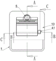
FIG. 1 is a schematic view (perspective view) of the mop bucket of this embodiment;
FIG. 2 is a schematic view of the mop bucket of this embodiment;
FIG. 3 is a cross-sectional view taken at A-A of FIG. 2;
FIG. 4 is a cross-sectional view taken at B-B of FIG. 2;
FIG. 5 is an enlarged view of FIG. 4 at D;
FIG. 6 is a cross-sectional view taken at C-C of FIG. 2;
FIG. 7 is a schematic view of the fixing frame and the fixing member of the present embodiment;
FIG. 8 is a schematic view of the mounting bracket and the driving mechanism of the present embodiment;
FIG. 9 is a schematic view of the operating member and the driving mechanism of the present embodiment in combination (with the fixing member removed);
FIG. 10 is a schematic view showing the operation member and the driving mechanism of the present embodiment.
Description of reference numerals: 1. a mop bucket; 11. a water storage area; 12. a mop placement area; 13. a fixed mount; 131. an extension wall; 132. a limiting member; 133. an opening; 2. a cleaning mechanism; 3. a drive mechanism; 31. a driving gear; 32. a first gear; 33. a one-way gear; 331. a unidirectional gear rotating shaft; 331-1, toggle teeth; 34. a second gear; 35. a fixing member; 351. a toothed region; 36. a third gear; 361. an abutting portion; 4. a control mechanism; 41. an operating member; 411. a stop portion; 412. a limiting part; 413. a drive section; 414. an operation section; 415. a pushing part 42, a reset piece; 5. a mop; 51. a mop head; 52. a mop handle.
Detailed Description
The following detailed description of embodiments of the present invention is provided in connection with the accompanying drawings and examples. The following examples are intended to illustrate the utility model but are not intended to limit the scope of the utility model.
In the description of the present invention, it should be noted that, unless otherwise explicitly specified or limited, the terms "mounted," "connected," and "connected" are to be construed broadly, e.g., as meaning either a fixed connection, a removable connection, or an integral connection; can be mechanically or electrically connected; they may be connected directly or indirectly through intervening media, or they may be interconnected between two elements. The specific meanings of the above terms in the present invention can be understood in specific cases to those skilled in the art.
In this embodiment:
as shown in fig. 1-3, 5 and 9, the driving device of the cleaning mechanism for the mop bucket of the embodiment is used for cleaning a mop head 51 of a mop 5 placed in the mop bucket 1, the driving device is used for controlling the operation and the stop of the cleaning mechanism 2; the mop bucket 1 comprises a water storage area 11 and a mop placing area 12, and the cleaning mechanism 2 is arranged at the position, close to the mop placing area 12, of the water storage area 11; the driving device comprises a driving mechanism 3 for driving the cleaning mechanism 2 to operate and a control mechanism 4 for controlling the operation and stop of the driving mechanism 3; the mop 5 drives the driving mechanism 3 to operate from top to bottom. Specifically, the mop 5 comprises a mop head 51 and a mop handle 52, and when the mop head 51 is rotated to be parallel to the mop handle 52, the mop head can be put into the mop bucket 1 for washing and squeezing. Adopt above-mentioned scheme, drive wiper mechanism 2 through drive arrangement and wash and wring out the mop, solved the manual work and washed the problem that can make dirty hand, and simple structure is reasonable, easy operation is convenient, compares manual cleaning effect good.
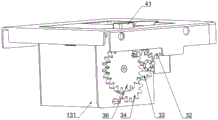
As shown in fig. 6, fig. 8-fig. 10, further, the driving mechanism 3 comprises a gear set, the gear set comprises a driving gear 31, a first gear 32 in transmission connection with the driving gear 31, a one-way gear 33 engaged with the first gear 32, and a second gear 34 engaged with the one-way gear 33, wherein the driving gear 31 is driven by the mop 5 to operate, and the second gear 34 is in transmission connection with the cleaning mechanism 2. Further, a fixing member 35 is disposed outside the one-way gear 33, and the fixing member 35 has a matching tooth-shaped region 351 with the one-way gear 33. By adopting the scheme, the gear area is matched with the one-way gear 33, so that the one-way operation of the one-way gear 33 can be ensured, and the mop 5 cannot rotate reversely when moving upwards, so that the cleaning mechanism 2 cannot be driven, and the mop head 51 can be squeezed.
As shown in fig. 6, fig. 8 to fig. 9, further, the one-way gear 33 has a one-way gear rotating shaft 331, a dial tooth 331-1 is provided on the one-way gear rotating shaft 331, the dial tooth 331-1 is in meshing connection with a third gear 36, the third gear 36 is connected to the control mechanism 4, and the control mechanism 4 is configured to control operation and stop of the third gear 36. Preferably, the one-way gear rotating shaft 331 is provided with a shifting tooth 331-1, the one-way gear 33 rotates one turn, and the shifting tooth 331-1 shifts the third gear 36 once to rotate by one tooth. Preferably, the gear ring of the third gear 36 is provided with 21 teeth, and the one-way gear 33 rotates 21 times, and the third gear 36 rotates exactly once. Preferably, the mop 5 is inserted into the mop placing area 12 from top to bottom until the mop is completely inserted, the driving gear 31 can be driven to rotate for 7 circles, the one-way gear 33 rotates for 7 circles, and the third gear 36 is shifted to rotate for 7 teeth, so that the mop 5 is inserted for 3 times, and the third gear 36 just rotates for one circle.
Further, the control mechanism 4 includes an operating member 41 and a reset member 42 connected to the operating member 41 such that the operating member 41 tends to face upward at all times. Preferably, the operating member 41 includes a driving portion 413 for driving the third gear 36 and an operating portion 414 for facilitating the operation of the user. Further, the operating member 41 has a stopping portion 411 for controlling the third gear 36 to stop, and correspondingly, the third gear 36 has an abutting portion 361 matched with the stopping portion 411; the third gear 36 rotates until the abutting portion 361 contacts the stop portion 411, and the third gear 36 stops operating; the operation of the operating member 41 disengages the stop portion 411 from the abutting portion 361, and the third gear 36 is re-operated.
As shown in fig. 1, 7-10, further, a fixing frame 13 is installed at the open end of the mop bucket 1, the lower end of the fixing frame 13 extends downwards to form an extending wall 131, and the fixing member 35 is detachably installed on the extending wall 131. Preferably, the stopping portion 411 is formed at an end of the third gear 36 close to the fixed frame 13, and when the operating element 41 is at the initial position, the stopping portion 411 of the operating element 41 is restricted from contacting the abutting portion 361 of the third gear 36, and the rotation of the third gear 36 is stopped; meanwhile, the operating element 41 is provided with a pushing portion 415, when the operating element 41 is pressed, the abutting portion 361 moves downwards, the stop portion 411 is separated from the abutting portion 361, the pushing portion 415 pushes the teeth of the third gear 36 to rotate, meanwhile, the stop portion 411 is driven to rotate, then the pressing of the operating element 41 is stopped, when the operating element 41 returns to the initial position, the stop portion 411 does not contact the abutting portion 361, and the third gear 36 can be driven to rotate by the one-way gear 33. Preferably, the driving gear 31 is rotatably mounted on the fixing frame 13; the fixing member 35 is mounted to the fixing frame 13 to form a space for accommodating the first gear 32, the one-way gear 33, the second gear 34, and the third gear 36. By adopting the above scheme, the fixing piece 35 is detachably mounted on the fixing frame 13, which is beneficial to subsequent maintenance of the gear set.
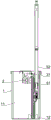
As shown in fig. 4-5 and 9-10, further, the inner wall of the fixing frame 13 extends downward to form a limiting member 132, and one end of the resetting member 42 is connected to the operating member 41, and the other end is connected to the limiting member 132. Preferably, the limiting member 132 has an L-shaped longitudinal section. Preferably, the limiting member 132 is disposed at the top end of the third gear 36, and does not limit the rotation of the third gear 36. Specifically, the reset member 42 is disposed between the operating member 41 and the limiting member 132, so that the operating member 41 is mounted on the driving frame, when the operating member 41 is pressed, the reset member 42 receives a stored elastic potential energy, and stops pressing, and the elastic potential energy of the reset member 42 provides an acting force for the operating member 41, so that the operating member 41 can be restored to an initial position. Further, the fixing frame 13 is provided with an opening 133 through which the operating element 41 passes, and the operating element 41 has a stopper 412 for restricting the operating element from being detached from the fixing frame 13. Further, the restoring member 42 includes a compression spring.
The working principle of the embodiment is as follows:
when cleaning is needed, the operating element 41 is pressed, the abutting part 361 of the operating element 41 moves downwards, the pushing part pushes the third gear 36 to rotate, the stopping part 411 of the third gear 36 rotates to be separated from the abutting part 361 of the operating element 41, the third gear 36 can be driven by the one-way gear 33, the mop 5 is inserted from top to bottom, the mop head 51 of the mop 5 drives the driving gear 31 to rotate, the cleaning mechanism 2 is driven to operate through the second gear 34, cleaning of the mop 5 is carried out, and when the mop 5 is used, the resetting element 42 is squeezed to store elastic potential energy;
after the operating element 41 is stopped being pressed, the elastic potential energy of the reset element 42 restores the operating element 41 to the initial position, after the mop 5 is inserted for 3 times, the third gear 36 just rotates for one circle, at this time, the stop part 411 of the third gear 36 is limited by the abutting part 361 of the operating element 41, the third gear 36 stops running, so that the cleaning mechanism 2 stops running, and the mop head 51 is squeezed; it should be noted that when the mop 5 is drawn out upward, the cleaning mechanism 2 cannot be driven to operate due to the function of the one-way gear 33.
The above is only a preferred embodiment of the present invention, and it should be noted that, for those skilled in the art, it is possible to make several improvements and modifications without departing from the technical principle of the present invention, and these improvements and modifications should also be considered as the protection scope of the present invention.
Claims (10)
1. A drive arrangement for a cleaning mechanism of a mop bucket, the cleaning mechanism (2) being used for cleaning a mop head (51) of a mop (5) placed in the mop bucket (1), the drive arrangement being used for controlling the operation and stop of the cleaning mechanism (2), characterized in that: the mop bucket (1) comprises a water storage area (11) and a mop placing area (12), and the cleaning mechanism (2) is arranged at the position, close to the mop placing area (12), of the water storage area (11); the driving device comprises a driving mechanism (3) for driving the cleaning mechanism (2) to operate and a control mechanism (4) for controlling the operation and stop of the driving mechanism (3); the mop (5) drives the driving mechanism (3) to operate from top to bottom.
2. The drive for a cleaning mechanism for a mop bucket of claim 1, wherein: the driving mechanism (3) comprises a gear set, the gear set comprises a driving gear (31), a first gear (32) in transmission connection with the driving gear (31), a one-way gear (33) meshed with the first gear (32), and a second gear (34) meshed with the one-way gear (33), wherein the driving gear (31) is driven by the mop (5) to operate, and the second gear (34) is in transmission connection with the cleaning mechanism (2).
3. The drive for a cleaning mechanism for a mop bucket of claim 2, wherein: a fixing piece (35) is arranged on the outer side of the one-way gear (33), and the fixing piece (35) is provided with a tooth-shaped area (351) matched with the one-way gear (33).
4. The drive for a cleaning mechanism for a mop bucket of claim 2, wherein: one-way gear (33) have one-way gear axis of rotation (331), be equipped with on one-way gear axis of rotation (331) and dial tooth (331-1), it is connected with third gear (36) to dial tooth (331-1) meshing, third gear (36) are connected control mechanism (4), control mechanism (4) are used for controlling the operation and the stopping of third gear (36).
5. The drive for a cleaning mechanism for a mop bucket of claim 4, wherein: the control mechanism (4) comprises an operating element (41) and a resetting element (42) which is connected with the operating element (41) and enables the operating element (41) to have a trend of always facing upwards.
6. The drive for a cleaning mechanism for a mop bucket of claim 5, wherein: the operating piece (41) is provided with a stop part (411) for controlling the third gear (36) to stop, and correspondingly, the third gear (36) is provided with an abutting part (361) matched with the stop part (411); the third gear (36) rotates until the abutting portion (361) comes into contact with the stop portion (411), and the third gear (36) stops operating; the operation member (41) is operated to disengage the stop portion (411) from the abutting portion (361), and the third gear (36) is operated again.
7. The drive for a cleaning mechanism for a mop bucket of claim 4, wherein: a fixing frame (13) is installed at the opening end of the mop bucket (1), the lower end of the fixing frame (13) extends downwards to form an extending wall (131), and the fixing piece (35) is detachably installed on the extending wall (131).
8. The drive for a cleaning mechanism for a mop bucket of claim 7, wherein: the inner wall of mount (13) downwardly extending forms a locating part (132), the one end of piece (42) that resets is connected operating parts (41), the other end connection the locating part (132).
9. The drive for a cleaning mechanism for a mop bucket of claim 7, wherein: the fixing frame (13) is provided with an opening (133) for the operating piece (41) to pass through, and the operating piece (41) is provided with a limiting part (412) for limiting the operating piece to be separated from the fixing frame (13).
10. A drive arrangement for a cleaning mechanism for a mop bucket according to any one of claims 5 to 9, wherein: the return member (42) comprises a compression spring.
Priority Applications (1)
| Application Number | Priority Date | Filing Date | Title |
|---|---|---|---|
| CN202120369724.9U CN215305627U (en) | 2021-02-08 | 2021-02-08 | Driving device for cleaning mechanism of mop bucket |
Applications Claiming Priority (1)
| Application Number | Priority Date | Filing Date | Title |
|---|---|---|---|
| CN202120369724.9U CN215305627U (en) | 2021-02-08 | 2021-02-08 | Driving device for cleaning mechanism of mop bucket |
Publications (1)
| Publication Number | Publication Date |
|---|---|
| CN215305627U true CN215305627U (en) | 2021-12-28 |
Family
ID=79581321
Family Applications (1)
| Application Number | Title | Priority Date | Filing Date |
|---|---|---|---|
| CN202120369724.9U Active CN215305627U (en) | 2021-02-08 | 2021-02-08 | Driving device for cleaning mechanism of mop bucket |
Country Status (1)
| Country | Link |
|---|---|
| CN (1) | CN215305627U (en) |
-
2021
- 2021-02-08 CN CN202120369724.9U patent/CN215305627U/en active Active
Similar Documents
| Publication | Publication Date | Title |
|---|---|---|
| CN110664328B (en) | Indoor wall cleaning equipment | |
| CN214804444U (en) | Mop assembly and cleaning robot | |
| CN211674011U (en) | Floor wiping brush head with dust collection function | |
| CN107348913A (en) | Floor mopping cloth strainer and floor cleaning machine | |
| CN215383722U (en) | Cleaning robot | |
| CN215305627U (en) | Driving device for cleaning mechanism of mop bucket | |
| CN210788264U (en) | Fill electric pile and clean system | |
| CN218552238U (en) | Ground cleaning device | |
| CN101879051A (en) | Electrical mopping and sweeping machine | |
| KR102025847B1 (en) | Manual Vacuum Cleaner | |
| CN210249724U (en) | Cleaning device | |
| CN112220425A (en) | Device for automatically cleaning and tidying bowls and chopsticks in household kitchen | |
| CN211155623U (en) | Mop bucket | |
| CN215305632U (en) | Driving device of cleaning mechanism for mop bucket | |
| CN108126962B (en) | A kind of cleaning device | |
| CN112890710A (en) | Rotary mop cleaning tool with centrifugal clamping mechanism | |
| KR200458082Y1 (en) | a wet floorcloth cleaner of floorcloth fiber mounting and holder having thereof | |
| CN112057001A (en) | Floor cleaning robot | |
| CN214804521U (en) | Mop bucket | |
| CN217013915U (en) | Cleaning device of cleaning machine and cleaning machine | |
| CN213821284U (en) | Electric mop cleaning barrel with efficient cleaning and draining functions | |
| CN217310161U (en) | Mop device | |
| CN215777875U (en) | Water guide device | |
| CN216907835U (en) | Automatic cleaning device and electric cleaner | |
| CN218528640U (en) | Round brush subassembly for ground cleaning device |
Legal Events
| Date | Code | Title | Description |
|---|---|---|---|
| GR01 | Patent grant | ||
| GR01 | Patent grant |