CN215208144U - Erection equipment - Google Patents
Erection equipment Download PDFInfo
- Publication number
- CN215208144U CN215208144U CN202121253576.0U CN202121253576U CN215208144U CN 215208144 U CN215208144 U CN 215208144U CN 202121253576 U CN202121253576 U CN 202121253576U CN 215208144 U CN215208144 U CN 215208144U
- Authority
- CN
- China
- Prior art keywords
- leg
- main beam
- supporting
- erection
- front auxiliary
- Prior art date
- Legal status (The legal status is an assumption and is not a legal conclusion. Google has not performed a legal analysis and makes no representation as to the accuracy of the status listed.)
- Active
Links
Images


Abstract
The utility model provides an erect equipment relates to subway vehicle section construction erection equipment technical field, erect equipment and be used for erectting assembled vehicle section station, assembled vehicle section station includes multilayer structure, it includes to erect equipment: a main beam; the hoisting trolley is movably arranged on the main beam and used for hoisting the prefabricated box girder; the support leg assembly comprises a front support leg and a middle support leg which are arranged on the main beam; when the front supporting legs are in a working state, the height of the front supporting legs is greater than that of the middle supporting legs; the front supporting legs are suitable for standing on the lower structure of the assembled vehicle section/station, and the middle supporting legs are suitable for standing on the upper structure of the assembled vehicle section/station; the front supporting leg and the middle supporting leg are respectively in driving connection with one cart travelling mechanism. The utility model discloses an erect equipment, carry out the assembled construction to the railcar section through this equipment, saving manpower, time and energy consumption cost that can be very big.
Description
Technical Field
The utility model relates to a subway vehicle section construction erects equipment technical field, particularly, relates to an erection equipment.
Background
In recent years, along with the construction of subway lines of various cities in the country, governments at all levels have made high demands on the efficiency, cost, influence on the surrounding environment and the like of subway construction.
SUMMERY OF THE UTILITY MODEL
The utility model discloses aim at solving the current railcar section and adopt the low, big technical problem of environmental impact of efficiency of construction that the cast in situ construction exists.
In order to achieve the above object, the utility model provides an erect equipment, including being used for erectting fabricated vehicle section/station, fabricated vehicle section/station includes multilayer structure, erect equipment and include:
a main beam;
the hoisting trolley is movably arranged on the main beam and used for hoisting the prefabricated box girder;
a leg assembly including a front leg and a center leg disposed on the main beam; when in a working state, the height of the front supporting leg is higher than that of the middle supporting leg; the front supporting leg is suitable for standing on a lower structure of the assembled vehicle section/station, and the middle supporting leg is suitable for standing on an upper structure of the assembled vehicle section/station;
and the front supporting leg and the middle supporting leg are respectively in driving connection with one cart running mechanism.
Erect equipment, walk the mechanism drive through the cart of preceding landing leg and well landing leg bottom the girder carries out the sideslip or indulges and moves, the trolley hoist in advance prefabricated case roof beam and move on the girder to the case roof beam that will treat to assemble moves the position and assembles the completion, compares in the construction methods of current cast-in-place case roof beam, adopts the equipment of erectting of this application to carry out assembled vehicle section/station and erects and to make the efficiency of construction show the improvement.
Optionally, the leg assembly further comprises a front auxiliary leg and a rear leg arranged on the main beam, the front auxiliary leg being adapted to stand on an underlying structure of the fabricated vehicle section/station, and the rear leg being adapted to stand on an overlying structure of the fabricated vehicle section/station.
Optionally, the front auxiliary supporting leg, the front supporting leg, the middle supporting leg and the rear supporting leg are respectively provided with a telescopic structure, and the front auxiliary supporting leg, the front supporting leg, the middle supporting leg and the rear supporting leg are all suitable for adjusting the supporting height through the telescopic structures.
Optionally, a walking wheel is arranged below the front auxiliary supporting leg, and a fixed fulcrum is arranged below the rear supporting leg and used for supporting the main beam;
the front supporting legs and/or the middle supporting legs are suitable for driving the main beams to move forwards through the cart running mechanism, and the front auxiliary supporting legs and the front supporting legs are suitable for being stretched in a crossed mode and supported on the lower-layer framework, so that the erection equipment is over-high and uneven in the longitudinal direction.
Optionally, the main beam is a single main beam or a double main beam, when the single main beam is adopted, the front support leg and the trolley are respectively connected with the lower lug of the main beam through a first suspension gear and a second suspension gear, and the middle support leg is connected with the upper lug of the main beam through a third suspension gear;
when the double-girder is adopted, the front supporting leg and the middle supporting leg are respectively connected with the lower lug of the girder through a fourth supporting hanging wheel and a fifth supporting hanging wheel, and the crane trolley runs above the girder.
Optionally, walking wheels are respectively arranged below the front auxiliary supporting leg and the rear supporting leg, so as to be suitable for the bidirectional walking of the erection equipment.
Optionally, the front auxiliary leg, the front leg, the middle leg and the rear leg are of a segmented type, the front auxiliary leg is installed with one more segment than the rear leg, the front leg is installed with one more segment than the middle leg, the length of the segment where the front auxiliary leg is installed with more segment than the rear leg is the same as the length of the segment where the front leg is installed with more segment than the middle leg, and the segments installed on the front leg and the front auxiliary leg are suitable for being installed on the middle leg and the rear leg after being detached, so that the erection equipment can be erected reversely;
or the front supporting leg and the rear supporting leg jack the main beam in a walking manner through the telescopic structure so as to enable the erection equipment to be reversely erected.
Optionally, the front auxiliary leg comprises a first leg and a second leg, the front leg comprises a third leg and a fourth leg, the third leg and the fourth leg are located between the first leg and the second leg, and the first leg and the third leg, the third leg and the fourth leg, and the second leg and the fourth leg are respectively suitable for being connected through a connecting rod.
Optionally, the cart running mechanism is adapted to rotate 360 ° relative to the front or middle support leg, and the cart running mechanism is of a wheel-rail type or a tire type.
Optionally, the trolley is provided with a plurality of spreaders, at least one spreader being a rotary spreader.
Drawings
Fig. 1 is a first schematic structural view of the erection equipment according to the embodiment of the present invention;
FIG. 2 is a schematic view of the mounting structure of the front auxiliary leg and the front leg on the main beam in FIG. 1;
FIG. 3 is a schematic view of the mounting structure of the center leg of FIG. 1 on the main beam;
FIG. 4 is a schematic view of the mounting structure of the rear leg on the main beam in FIG. 1;
fig. 5 is a schematic view of a second structure of the erecting equipment according to the embodiment of the present invention;
FIG. 6 is a schematic view of the mounting structure of the front auxiliary leg and the front leg on the main beam in FIG. 5;
FIG. 7 is a schematic view of the mounting structure of the center leg on the main beam in FIG. 5;
FIG. 8 is a schematic view of the mounting structure of the rear leg on the main beam of FIG. 5;
fig. 9 is a third schematic structural view of the erecting device according to the embodiment of the present invention;
FIG. 10 is a schematic view of the mounting structure of the rear leg on the main beam of FIG. 9;
fig. 11 is a schematic structural diagram corresponding to a first state in the first erection method according to the embodiment of the present invention;
fig. 12 is a schematic structural diagram corresponding to the second state in the first erection method according to the embodiment of the present invention;
fig. 13 is a schematic structural diagram corresponding to a third state in the first erection method according to the embodiment of the present invention;
fig. 14 is a schematic structural diagram corresponding to a fourth state in the first erection method according to the embodiment of the present invention;
fig. 15 is a schematic structural diagram corresponding to a fifth state in the first erection method according to the embodiment of the present invention;
fig. 16 is a schematic structural diagram corresponding to a sixth state in the first erection method according to the embodiment of the present invention;
fig. 17 is a schematic structural diagram corresponding to a seventh state in the first erection method according to the embodiment of the present invention;
fig. 18 is a schematic structural diagram corresponding to an eighth state in the first erection method according to the embodiment of the present invention;
fig. 19 is a schematic structural diagram corresponding to a ninth state in the first erection method according to the embodiment of the present invention;
fig. 20 is a schematic structural diagram corresponding to a tenth state in the first erection method according to the embodiment of the present invention;
fig. 21 is a schematic structural diagram of the apparatus S01 after traversing in the method for preventing surface unevenness according to the embodiment of the present invention;
fig. 22 is a schematic structural diagram of the method for preventing uneven surface according to the embodiment of the present invention, in which S02 corresponds to the first support point of the front leg after contracting;
fig. 23 is a schematic structural diagram of the method for preventing uneven surface according to the embodiment of the present invention, wherein S03 corresponds to the method after contracting the second support point of the front leg;
fig. 24 is a schematic structural diagram of the apparatus S03 after traversing in the method for preventing surface unevenness according to the embodiment of the present invention;
FIG. 25 is a fourth structural schematic diagram of the erecting equipment according to the embodiment of the present invention;
FIG. 26 is a top view of the front leg and front auxiliary frame rail of the erection device of FIG. 25;
FIG. 27 is a schematic view of the center leg frame rail of the erection device of FIG. 25 in a lowermost position;
FIG. 28 is a schematic view of the lower most rear leg rest bar of the erection device of FIG. 25;
fig. 29 is a schematic structural diagram corresponding to step one of the second erection method according to the embodiment of the present invention;
fig. 30 is a schematic structural diagram corresponding to step two of the second erection method according to the embodiment of the present invention;
fig. 31 is a schematic structural diagram corresponding to step four of the second erection method according to the embodiment of the present invention;
fig. 32 is a schematic structural diagram corresponding to step five of the second erection method according to the embodiment of the present invention;
fig. 33 is a schematic structural diagram corresponding to step six of the second erection method according to the embodiment of the present invention;
fig. 34 is a schematic structural diagram corresponding to step seven of the second erection method according to the embodiment of the present invention;
fig. 35 is a schematic structural diagram corresponding to step eight of the second erection method according to the embodiment of the present invention;
fig. 36 is a schematic structural diagram corresponding to step nine of the second erection method according to the embodiment of the present invention;
fig. 37 is a schematic structural diagram corresponding to step ten of the second erection method according to the embodiment of the present invention;
fig. 38 is a schematic structural diagram corresponding to step eleven of the second erection method according to the embodiment of the present invention;
fig. 39 is a schematic structural diagram corresponding to step twelve of the second erection method according to the embodiment of the present invention;
fig. 40 is a schematic structural diagram corresponding to a thirteenth step of the second erection method according to the embodiment of the present invention;
fig. 41 is a schematic structural view of a tower crane passed by a fourth erection device in the embodiment of the present invention;
fig. 42 is a schematic structural diagram corresponding to S11 in the through-hollowing method according to the embodiment of the present invention;
fig. 43 is a schematic structural diagram corresponding to S12 in the through-hollowing method according to the embodiment of the present invention;
fig. 44 is a schematic structural diagram corresponding to S13 in the through-hollowing method according to the embodiment of the present invention;
fig. 45 is a schematic structural diagram of the through-hollowing method of the embodiment of the present invention corresponding to S14.
Description of reference numerals:
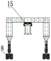
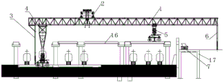
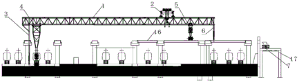
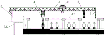
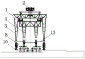
1. a main beam; 2. a trolley; 3. a front auxiliary leg; 4. a front leg; 5. a middle support leg; 6. a rear leg; 7. carrying a beam vehicle; 8. a cart travelling mechanism; 9. a retractable structure; 10. a running wheel; 11. fixing the supporting point; 12. a spreader; 13. a connecting rod; 14. a first change gear; 15. a third hanging wheel; 16. a box girder; 17. an enclosure structure; 18. and (5) tower crane.
Detailed Description
In order to make the aforementioned objects, features and advantages of the present invention more comprehensible, embodiments accompanied with figures are described in detail below.
In the description of the present invention, it should be noted that terms such as "upper", "lower", "front", "rear", and the like in the embodiments indicate terms of orientation, and are only used for simplifying the description of positional relationships based on the drawings of the specification, and do not represent that the elements, devices, and the like indicated in the description must be operated according to specific orientations and defined operations and methods, configurations, and such terms of orientation do not constitute limitations of the present invention.
In addition, it should be noted that, in the description of the present invention, unless otherwise explicitly specified or limited, the terms "mounted," "connected," and "coupled" are to be construed broadly and may include, for example, a fixed connection, a detachable connection, or an integral connection; they may be connected directly or indirectly through intervening media, or they may be interconnected between two elements. The specific meaning of the above terms in the present invention can be understood by those skilled in the art according to specific situations.
The subway assembly type vehicle section/station is a latest form of an assembly type building and comprises the procedures of digging a foundation pit, hoisting pier columns, splicing box girders and the like, wherein the pier columns and the box girders need to be prefabricated in advance, reinforcing steel bars and concrete adopted in the traditional construction are poured in a factory to form prefabricated components, then the prefabricated components are transported to an installation site through transportation tools in the process of erection construction, the components are assembled, the purpose of rapid construction is achieved, and the factory production of construction of a building structure is realized.
As shown in fig. 1-4, the utility model discloses an erection equipment of first embodiment for erect fabricated vehicle section/station, fabricated vehicle section/station includes multilayer structure, erection equipment includes:
a main beam 1;
the hoisting trolley 2 is movably arranged on the main beam 1 and used for hoisting and transporting the prefabricated box girder;
a leg assembly comprising a front leg 4 and a middle leg 5 disposed on the main beam 1; when in the working state, the height of the front support leg 4 is higher than that of the middle support leg 5; the front leg 4 is adapted to stand on the substructure of the fabricated vehicle section/station, and the center leg 5 is adapted to stand on the superstructure of the fabricated vehicle section/station;
the front supporting leg 4 and the middle supporting leg 5 are respectively in driving connection with one cart travelling mechanism 8.
In the embodiment, the crane trolley 2 moves along the direction of the main beam 1, so as to lift the prefabricated box girder and walk along the direction of the main beam 1 to adjust the position of the girder piece, and the cart traveling mechanism 8 drives the main beam 1 to move transversely or longitudinally, so as to move the prefabricated box girder 16 to be assembled and poured to a preset position for assembling operation, wherein the transverse movement refers to the movement along the width direction of the main beam 1, and the longitudinal movement refers to the movement along the length direction of the main beam 1. The erection equipment of this application is adopted and is realized erectting the assembled of subway vehicle section, compares and is showing in the construction mode of current cast in situ box girder and promotes and erect efficiency.
The front supporting legs 4 are higher than the middle supporting legs 5, the structural design of the high-low legs can meet the erection requirement of subway vehicle section buildings, the subway vehicle sections are generally multi-layer buildings, when a first layer is erected, the front supporting legs 4 stand in a foundation pit, and the middle supporting legs 5 stand on the erected and poured first-layer box girders 16; when erecting the second floor, the front support legs 4 stand on the first floor, and the middle support legs 5 stand on the second floor box girder 16 which is erected and poured.
Optionally, the leg assembly further comprises a front auxiliary leg 3 and a rear leg 6 arranged on the main beam 1, the front auxiliary leg 3 is suitable for standing on the lower structure, and the rear leg 6 is suitable for standing on the upper structure.
In this embodiment, the front auxiliary leg 3, the front leg 4, the middle leg 5 and the rear leg 6 are sequentially connected to the main beam 1 in this order; the front auxiliary supporting legs 3 are mainly used for enabling equipment to pass through the height unevenness by being converted with the front supporting legs 4 when the equipment walks to the height unevenness position; the front auxiliary leg 3 and the rear leg 6 can also be used to assist in support.
Optionally, the trolley 2 is provided with a plurality of spreaders 12, at least one spreader 12 being a rotary spreader.
In the embodiment, the trolley 2 is provided with a plurality of lifting appliances 12, so that the mounting efficiency of the beam piece can be obviously improved; the rotary lifting appliance on the lifting trolley 2 can transversely or longitudinally place the beam pieces according to requirements, and the rest fixed lifting appliances are mainly used for erecting the beam pieces at the sides of some foundation pits; preferably, a trolley 2 with cantilevers at two ends and three lifting appliances in total is adopted, the middle lifting appliance can rotate, and the lifting appliances at two ends are fixed lifting appliances.
In other embodiments, the trolley 2 with a rotating function can be adopted, so that the same technical effect as the embodiment can be achieved, and the beam piece can be rotated to a proper placing position.
Optionally, the front auxiliary leg 3, the front leg 4, the middle leg 5, and the rear leg 6 are respectively provided with a telescopic structure 9, and the front auxiliary leg 3, the front leg 4, the middle leg 5, and the rear leg 6 are all adapted to adjust the supporting height through the telescopic structure 9.
In this embodiment, the telescopic structures 9 are installed on the support legs, so that the erection stability can be ensured under uneven road conditions, the erection terrain is not limited, and the requirements of the terrain can be better met.
In this embodiment, the front auxiliary leg 3 and the rear leg 6 are fixedly connected to the main beam 1, and the front leg 4 and the middle leg 5 are slidably connected to the main beam 1. The front support leg 4 and the middle support leg 5 can move back and forth along the main beam 1.
Optionally, one of the front auxiliary leg 3 and the rear leg 6 is provided with a running wheel 10, and the other is a fixed leg for supporting the main beam 1.
The first condition is as follows: a walking wheel 10 is arranged below the front auxiliary supporting leg 3, and a fixed supporting point 11 is arranged below the rear supporting leg 6; case two: the front auxiliary supporting leg 3 is a fixed supporting point 11, and a walking wheel 10 is arranged below the rear supporting leg 6.
In this embodiment, the front supporting legs 4 run along the length direction of the main beam 1 through the running wheels 10, and are used for the erection equipment to pass through the height and unevenness through the leg conversion when running to the height and unevenness position, and in addition, when the load of a certain supporting leg is too large and exceeds the bearing requirement, the load transfer is performed in a manner that: for example, when the load of the middle supporting leg is overlarge, the rear supporting leg actively lifts the load upwards to the main beam by jacking the oil cylinder below the rear supporting leg so as to share part of the load of the middle supporting leg and enable the load to meet the requirement; the front auxiliary supporting leg 3 can bear partial load to share the wheel pressure of the front supporting leg so as to meet the bearing requirement of the beam piece.
Optionally, the main beam 1 is a single main beam or a double main beam; when a single main beam is adopted, as shown in fig. 5-8, the front support leg 4 and the trolley 2 are respectively connected with the lower lug of the main beam 1 through a first suspension gear 14 and a second suspension gear, and the middle support leg 5 is connected with the upper lug of the main beam 1 through a third suspension gear 15;
when the double main beams are adopted, as shown in fig. 1-4, the front supporting leg 4 and the middle supporting leg 5 are respectively connected with the lower part of the main beam 1 through a fourth supporting hanging wheel and a fifth supporting hanging wheel, and the trolley 2 runs above the main beam 1.
In this embodiment, the main beam 1 may be a single main beam or a double main beam.
When the single main beam is adopted, the weight reduction advantage is achieved; a certain distance is reserved between the middle supporting leg 5 and the rear supporting leg 6, so that a beam transporting trolley can pass through the beam transporting trolley, and the requirement of taking materials between the middle supporting leg 5 and the rear supporting leg 6 is met. The front supporting leg 4 is connected with the lower ear of the main beam 1 in a sliding way through a first hanging wheel 14, so that the front supporting leg 4 can move back and forth along the direction of the main beam 1; the trolley 2 is in sliding connection with the lower lug of the main beam 1 through a second hanging wheel, so that the trolley 2 can move back and forth along the length direction of the main beam 1; the middle support leg 5 is connected with the upper ear of the main beam 1 in a sliding way through the third hanging wheel 15, so that the middle support leg 5 can move back and forth along the main beam 1.
When the double main beams are adopted, the stability of the structure can be improved; the middle supporting leg 5 and the rear supporting leg 6 are spaced at a certain distance, so that a beam transporting trolley can pass through the middle supporting leg 5 and the rear supporting leg 6, and the requirement of taking materials between the middle supporting leg 5 and the rear supporting leg 6 is met, and the point is the same as that of taking materials between a single main beam. The front supporting leg 4 and the middle supporting leg 5 slide on the main beam 1 through a fourth supporting change gear and a fifth supporting change gear. The trolley 2 runs on the main beam 1. When the double main beams 1 are adopted, the two main beams 1 are vertically connected through the connecting beam, and under the condition that the main beams 1 are not moved, the hoisting trolley 2 can move along the direction vertical to the main beams 1 to erect a plurality of box beams, so that the overall erection efficiency is improved.
Optionally, running wheels 10 are arranged below the front auxiliary supporting leg 3 and the rear supporting leg 6; the front auxiliary supporting leg 3, the front supporting leg 4, the middle supporting leg 5 and the rear supporting leg 6 are all in a sectional type.
In this embodiment, adopt the convenient nimble installation of use needs, the dismantlement festival section according to the scene of festival section to satisfy the demand to the landing leg height.
In the present embodiment, as shown in fig. 9 to 10, the front auxiliary leg 3 and the rear leg 6 have the same structural form, interface with the main beam 1, and base distance, and the front auxiliary leg 3 is different from the rear leg 6 only in that: the front auxiliary leg 3 is provided with one or more sections more than the rear leg 6, the front leg 4 and the middle leg 5 have the same structural form as the main beam 1 interface and base distance, and the front leg 4 and the middle leg 5 only differ from each other in that: the front leg 4 is installed with one or more sections more than the middle leg 5;
when the second layer of erection is to be carried out after the erection of the forward erection beam of the equipment is finished, a section with the same length is detached from the front auxiliary supporting leg 3 and the front supporting leg 4 and is respectively installed on the rear supporting leg 6 and the middle supporting leg 5, at the moment, the height of the rear supporting leg 6 and the height of the middle supporting leg 5 are greater than that of the front supporting leg 4 and the front auxiliary supporting leg 3, the rear supporting leg 6 and the middle supporting leg 5 stand on a lower layer structure (a first layer of box girder at the moment), the front auxiliary supporting leg 3 and the front supporting leg 4 stand on an upper layer structure (an enclosure structure outside a foundation pit), and then the steps of the first layer of erection (the functions of the rear supporting leg 6 and the middle supporting leg 5 during the reverse erection are equivalent to the front auxiliary supporting leg 3 and the front supporting leg 4 during the forward erection, and the functions of the front auxiliary supporting leg 3 and the front supporting leg 4 during the reverse erection are equivalent to the front supporting leg 6 and the front supporting leg during the erection of the forward erection beam, Middle support leg 5), can realize erectting the reverse frame roof beam of equipment, erect efficiently.
Naturally, instead of the above reverse erection by removing the leg sections, the whole leg wheel set can be removed together, for example, during the reverse erection, the front auxiliary leg 3 and the front leg 4 are removed together with the wheel set below from the main beam 1, and are installed at the positions of the rear leg 6 and the middle leg 5, the front rear leg 6 and the middle leg 5 are removed together with the wheel set below to be installed at the positions of the front auxiliary leg 3 and the front leg 4, and after the installation is completed, the erection of the second floor of box girder is started.
Optionally, the front auxiliary leg 3 comprises a first leg and a second leg, the front leg 4 comprises a third leg and a fourth leg, the third leg and the fourth leg are located between the first leg and the second leg, and the front leg 4 and the front auxiliary leg 3 are connected by a connecting rod 13.
In this embodiment, when the road is in an excessively uneven road condition, the front leg 4 is overlapped on the inner side of the front auxiliary leg 3 (that is, the front leg 4 and the front auxiliary leg 3 run into the same plane), and the first leg and the third leg, the third leg and the fourth leg, and the second leg and the fourth leg are connected by the connecting rod 13, so as to increase the rigidity and stability.
Optionally, the cart running gear 8 is adapted to rotate 360 ° with respect to the front leg 4 or the middle leg 5, and the cart running gear 8 is of a wheel-rail type or a tire-type.
In this embodiment, the cart running mechanism 8 can rotate 360 degrees to drive the erection equipment to move transversely or longitudinally; when the cart running mechanism 8 is in a wheel rail type, a double-rail wheel rail can be adopted.
Optionally, the telescopic structure 9 is in a telescopic oil cylinder, a motor-driven screw, a rack and pinion, a gear pin transmission or a winch stretching structure.
In this embodiment, the retraction of each leg generally adopts the mode of gradually lifting and gradually retracting the oil cylinder, and of course, the technical effect of the telescopic leg can also be achieved by adopting the mode of driving a screw rod, a gear rack, a gear pin transmission or a winch stretching by a motor.
Erection of a fabricated vehicle section/station can be performed using the erection equipment described in the first embodiment, and the concrete erection process exemplarily includes the following steps:
s1: the front leg 4 and the front auxiliary leg 3 of the erection device stand on the lower structure of the fabricated vehicle section/station, and the middle leg 5 and the rear leg 6 of the erection device stand on the upper structure of the fabricated vehicle section/station, as shown in the first state diagram of fig. 11.
In the step, when the device is initially positioned, the front support leg 4 and the front auxiliary support leg 3 of the erection device are positioned in the foundation pit, the middle support leg 5 of the erection device is positioned on an enclosure structure 17 outside the foundation pit, and the rear support leg 6 can be suspended and also can be positioned on the enclosure structure 17.
S2: the beam transporting vehicle 7 transports the prefabricated box girder to the lower part of the erection equipment, the lifting trolley 2 of the erection equipment lifts the girder, the longitudinal box girder and the transverse box girder which span the hollow are installed, and the box girder 16 on the opposite side is poured with a node and a laminated layer.
Exemplarily, wherein S2 includes:
s2.1, installing three middle-spanning rows of longitudinal beams below the erection equipment, and pouring nodes and superposed layers on the 1 st and 2 nd rows of box girders 16 on opposite sides, as shown in a second state diagram of fig. 12; and the erecting equipment moves transversely and continues to erect until the three rows of erecting equipment are completed. Of course, the three columns may be two columns or any other number of columns, which is only used as an example and is not meant to limit the present invention.
S2.2: the rear legs 6 are supported on a building envelope 17 outside the foundation pit, and the middle legs 5 are partially dismantled and stand on the poured first-layer box girder 16, as shown in a third state diagram in fig. 13.
S3: the front auxiliary supporting legs 3 are contracted, the front supporting legs 4 are not moved in standing position, a cart travelling mechanism 8 connected with the middle supporting legs 5 drives the main beam 1 of the erection equipment to move forwards, the front auxiliary supporting legs 3 extend downwards to be supported on the lower layer structure, and the middle supporting legs 5 and the rear supporting legs 6 stand on the erected box beam; the front legs 4 are advanced along the length of the main beam 1 and supported on the substructure.
Exemplarily, wherein the S3 includes:
s3.1: when the height of the front auxiliary supporting legs is over the longitudinal height, the front auxiliary supporting legs 3 are contracted and the front supporting legs 4 are driven to drive the whole erection equipment to move forwards in a row, and a fourth state diagram is shown in fig. 14;
s3.2: the front legs 4 are also simultaneously moved forward one row and the rear legs 6 are removed from part of the section waiting to stand on the poured first layer of box girders 16, as shown in the fifth state diagram of fig. 15.
And S3, the whole erection equipment moves forwards by one row, at the moment, the front supporting leg 4 and the front auxiliary supporting leg 3 stand in the foundation pit, and the middle supporting leg 5 and the rear supporting leg 6 stand on the poured first-layer box girder 16. Naturally, according to the actual needs, multiple rows of erection at a time can be adopted for erection, at this time, S3.1-S3.2 are repeated, the whole erection equipment is moved forward to the right position, and then the erection equipment is erected and assembled, such as the sixth state diagram and the seventh state diagram shown in fig. 16-17.
S4: operations S2-S3 are repeated until the front auxiliary leg 3, the front leg 4 are moved to stand to the last column of the lower structure, as shown in the eighth state diagram of fig. 18.
S5: operation S2 is repeated to complete the last column of padding.
In this step, part of the sections of the front auxiliary support legs 3 are removed, the front support legs 4 stand still, and the cart travelling mechanism 8 drives the main beam 1 to move forward, so that the front auxiliary support legs 3 stand on the upper-layer structure, as shown in a ninth state diagram shown in fig. 19; dismantling a part of the sections of the front support legs 4, moving the front support legs 4 to stand on the upper structure, transporting the beams by the beam transporting vehicle 7 to the lower part of the erection equipment, taking the beams by the hoisting trolley 2, and erecting and pouring the last column of box beams 16, as shown in a tenth state diagram of fig. 20.
S6: after the first layer of box girders 16 are erected and poured, the pier stud can be hoisted, and then the operations S1-S5 are repeated to erect the second layer of box girders 16, when the second layer of box girders 16 are erected, the lower layer structure in the step S1 is the first layer of box girders 16, and the upper layer structure is a building enclosure outside the foundation pit.
The erection equipment according to the first embodiment can be used for over-height and unevenness (transverse over-height and unevenness), and the process of specifically using the over-height and unevenness comprises the following steps:
s01: when the front auxiliary leg 3 and the front leg 4 of the erection device are located in the low plane of the uneven surface and the distance between the first leg of the front auxiliary leg 3 and the high plane of the uneven surface reaches a preset distance, the third leg and the fourth leg of the front leg 4 are supported on the ground, the first leg of the front auxiliary leg 3 and the second leg of the front auxiliary leg 3 are retracted from the ground, and the erection device is laterally moved until the first leg of the front auxiliary leg 3 is supported on the high plane, as shown in fig. 21.
In this step, when the height is too high and uneven, the third leg and the fourth leg of the front leg 4 are located between the first leg and the second leg of the front auxiliary leg 3 and located in the same plane, and the connecting rod 13 is used for connecting the front auxiliary leg 3 and the front leg 4 to increase the rigidity and stability.
The first leg of the front auxiliary leg 3 is the leg of the front auxiliary leg 3 close to the high side.
S02: when the erecting device is moved laterally until the distance between the third leg of the front leg 4 and the high surface reaches the preset distance, the third leg of the front leg 4 is retracted from the ground, and the traversing of the erecting device is continued until the third leg of the front leg 4 is supported on the high surface, as shown in fig. 22.
In this step, the third leg of the front leg 4 is the leg of the front leg 4 close to the high side.
S03: the second leg of the front auxiliary leg 3 is extended down to rest on the ground and the fourth leg of the front leg 4 is retracted off the ground, and the traversing of the erection device is continued until the fourth leg of the front leg 4 rests on the high surface, as shown in fig. 23-24.
S04: the second leg of the front auxiliary leg 3 is retracted and the erection device is moved laterally so that the second leg of the front auxiliary leg 3 is supported on the high surface, whereupon the erection device completes the transverse over-height and out-of-plane.
On the basis of the first embodiment, the utility model discloses the erection equipment of erection of assembled vehicle section station of second embodiment, preceding auxiliary leg 3 preceding landing leg 4 well landing leg 5 reaches back landing leg 6 all adopts monolithic structure, and each landing leg is connected with the extending structure 9 of big flexible stroke, and the below of each landing leg all takes the cart to walk capable mechanism 8, and concrete structure is shown as figure 25-28, and wherein trolley 2 is prior art, mainly plays the effect of lifting by crane case roof beam 16, and the erection equipment of this kind of structure can cross the erection of some fretwork positions and boundary beam.
Erection of a fabricated vehicle section/station can be performed using the erection equipment described in the second embodiment, and the concrete erection process exemplarily includes the following steps:
the method comprises the following steps: as shown in fig. 29, the front support leg 4 and the front auxiliary support leg 3 of the erection equipment stand are located in the foundation pit, and the middle support leg 5 and the rear support leg 6 stand on the road outside the foundation pit;
step two: as shown in fig. 30, the girder transporting vehicle 7 transports the girder to the lower part of the main girder 1 of the erection equipment, the trolley 2 lifts the girder, three rows of longitudinal and transverse beams in the span are installed, and the 1 st and 2 nd rows of box girders on the opposite sides are cast with nodes and superposed layers. (after the node and the superposed layer are poured, the upper layer can stand on the equipment);
step three: after three rows of supporting legs are erected, the box girder 16 at the initial position is poured, the middle supporting legs 5 are suspended and moved into the foundation pit along the main girder 1, and the cart travelling mechanisms 8 of the supporting legs are turned by 90 degrees;
step four: as shown in fig. 31, the middle support leg 5 rises into the foundation pit along the main beam 1, and the trolley 2 is positioned at the side of the front support leg 4;
step five: as shown in fig. 32, the erection equipment is moved forward to the place where the front auxiliary leg 3 meets the step;
step six: as shown in fig. 33, the front auxiliary leg 3 is retracted and suspended, and the front leg 4 and the middle leg 5 push the erection equipment to move forward one row, so that the front auxiliary leg 3 stands on the step;
step seven: as shown in fig. 34, the front leg 4 moves forward to the next row along the main beam 1, supports on the ground, and retracts the front auxiliary leg 3;
step eight: as shown in fig. 35, the middle leg 5 is retracted and suspended, and moves backwards along the main beam 1, so as to reduce the rear suspension distance (i.e. the distance between the middle leg 5 and the rear leg 6);
step nine: as shown in fig. 36, the rear leg 6 is retracted and suspended, and the main beam 1 of the erection equipment moves forward until the rear leg 6 stands on the erected box beam;
step ten: as shown in fig. 37, the erection equipment is integrally moved forward by two rows, and the cart running mechanisms 8 of the front auxiliary support legs 3, the front support legs 4, the middle support legs 5 and the rear support legs 6 are all turned by 90 degrees and are continuously erected;
step eleven: as shown in fig. 38, the erection of the beams is sequentially performed according to the above-mentioned erection manner until the last row, so that the erection of the first layer side is completed;
step twelve: as shown in fig. 39, the telescopic structure 9 of each leg lifts the main beam 1 upwards;
step thirteen: as shown in fig. 40, the front auxiliary support leg 3 and the front support leg 4 of the erection equipment stand on the erected first-layer box girder, and the middle support leg 5 and the rear support leg 6 stand on the outer enclosure of the foundation pit or the second-layer erected box girder, so as to erect the second-layer box girder.
The erection equipment of the second embodiment can pass through a tower crane, and the specific process of passing through the tower crane comprises the following steps: when the tower crane 18 is erected, the large arm direction of the tower crane 18 is perpendicular to the main beam 1 direction of the erection equipment by turning the tower crane 18, the height of the tower crane 18 is lowered, and the height of the main beam of the equipment is raised, so that the equipment passes through the tower crane 18, as shown in fig. 41.
The erecting equipment adopting the second embodiment can be used for passing through hollow, and for example, the specific process of passing through hollow is similar to the process of passing through high and low non-plane, and specifically comprises the following steps:
s11: when the front auxiliary leg 3 and the front leg 4 of the erection device are located at the hollow (or step), the first leg of the front auxiliary leg 3 is suspended, and the erection device continues to move laterally, so that the first leg of the front auxiliary leg 3 is supported on the next floor, as shown in fig. 42.
In the present embodiment, the third leg and the fourth leg of the front leg 4 are located between the first leg and the second leg of the front auxiliary leg 3, and at the initial time, the first leg, the second leg, the third leg and the fourth leg are located in the same plane. The first leg of the front auxiliary leg 3 is the leg of the front auxiliary leg 3 close to the next floor.
S12: the first leg support of the front auxiliary leg 3 stands on the next floor and suspends the third leg of the front leg 4, and the traversing of the erection device is continued so that the third leg of the front leg 4 is supported on the next floor, as shown in fig. 43.
S13: the fourth leg of the front leg 4 is suspended and the traversing of the erection device is continued so that the fourth leg is supported on the next level, as shown in figure 44.
S14: at this time, both the two legs of the front leg 4 are supported on the next layer, the second leg of the front auxiliary leg 3 is suspended, the erecting equipment continues to move transversely, so that the second leg of the front auxiliary leg 3 is also supported on the next layer, and the whole process of hollowing is completed, as shown in fig. 45.
Although the present disclosure has been described above, the scope of the present disclosure is not limited thereto. Various changes and modifications may be made by those skilled in the art without departing from the spirit and scope of the present disclosure, and these changes and modifications are intended to fall within the scope of the present disclosure.
Claims (10)
1. An erection device, for erecting a fabricated vehicle section/station including a multi-layer structure, the erection device comprising:
a main beam (1);
the lifting trolley (2) is movably arranged on the main beam (1) and is used for lifting and transporting the prefabricated box girder;
a leg assembly comprising a front leg (4) and a middle leg (5) disposed on the main beam (1); when in the working state, the height of the front supporting leg (4) is greater than that of the middle supporting leg (5); the front leg (4) is suitable for standing on the lower structure of the assembled vehicle section/station, and the middle leg (5) is suitable for standing on the upper structure of the assembled vehicle section/station;
the front supporting leg (4) and the middle supporting leg (5) are respectively in driving connection with the cart travelling mechanism (8).
2. Erection device according to claim 1, characterized in that said leg assembly further comprises a front auxiliary leg (3) and a rear leg (6) provided on said main beam (1), said front auxiliary leg (3) being adapted to stand on said substructure and said rear leg (6) being adapted to stand on said superstructure.
3. Erection device according to claim 2, characterized in that said front auxiliary leg (3), said front leg (4), said middle leg (5) and said rear leg (6) are provided with a telescopic structure (9) thereon, said front auxiliary leg (3), said front leg (4), said middle leg (5) and said rear leg (6) being adapted to adjust the support height by means of said telescopic structure (9).
4. Erection device according to claim 2, characterized in that under said front auxiliary leg (3) there are running wheels (10), under said rear leg (6) there are fixed fulcrums for supporting said main beam (1);
the front supporting leg (4) and/or the middle supporting leg (5) are/is suitable for driving the main beam (1) to move forwards through the cart running mechanism (8), and the front auxiliary supporting leg (3) and the front supporting leg (4) are suitable for being stretched in a cross mode and supported on the underlying structure, so that the erection equipment is over-high and over-low uneven in the longitudinal direction.
5. The erection equipment according to claim 4, wherein the main beam (1) is a single main beam or a double main beam, when a single main beam is adopted, the front support leg (4) and the trolley (2) are respectively connected with the lower lug of the main beam (1) through a first suspension gear (14) and a second suspension gear, and the middle support leg (5) is connected with the upper lug of the main beam (1) through a third suspension gear (15);
when the double-girder is adopted, the front supporting leg (4) and the middle supporting leg (5) are respectively connected with the lower lug of the girder (1) through a fourth supporting hanging wheel and a fifth supporting hanging wheel, and the trolley (2) runs above the girder (1).
6. Erection device according to claim 3, characterized in that running wheels (10) are provided under the front auxiliary leg (3) and the rear leg (6), respectively, to be adapted to the bidirectional running of the erection device.
7. The erection device according to claim 6, wherein said front auxiliary leg (3), said front leg (4), said middle leg (5) and said rear leg (6) are all of a segmented type, said front auxiliary leg (3) is installed at a greater length than said rear leg (6), said front leg (4) is installed at a greater length than said middle leg (5), said front auxiliary leg (3) is installed at a greater length than said rear leg (6) than said middle leg (5), said segments installed on said front leg (4) and said front auxiliary leg (3) are adapted to be removed and then installed on said middle leg (5) and said rear leg (6) to reverse the erection device;
or the front supporting leg (4) and the rear supporting leg (6) jack the main beam (1) in a walking manner through the telescopic structure (9) so as to enable the erection equipment to be reversely erected.
8. Erection device according to claim 2, characterized in that said front auxiliary leg (3) comprises a first leg and a second leg, said front leg (4) comprises a third leg and a fourth leg, said third leg and said fourth leg being located between said first leg and said second leg, said first leg and said third leg, said third leg and said fourth leg and said second leg and said fourth leg being adapted to be connected by means of a connecting rod (13), respectively.
9. Erection device according to claim 2, characterized in that said cart running gear (8) is adapted to make a 360 ° rotation with respect to said front (4) or middle (5) legs, said cart running gear (8) being of the wheel-track or wheel-tyre type.
10. Erection device according to claim 1, characterized in that said trolley (2) is provided with a plurality of spreaders (12), at least one of said spreaders (12) being a rotary spreader.
Priority Applications (1)
| Application Number | Priority Date | Filing Date | Title |
|---|---|---|---|
| CN202121253576.0U CN215208144U (en) | 2021-06-02 | 2021-06-02 | Erection equipment |
Applications Claiming Priority (1)
| Application Number | Priority Date | Filing Date | Title |
|---|---|---|---|
| CN202121253576.0U CN215208144U (en) | 2021-06-02 | 2021-06-02 | Erection equipment |
Publications (1)
| Publication Number | Publication Date |
|---|---|
| CN215208144U true CN215208144U (en) | 2021-12-17 |
Family
ID=79423632
Family Applications (1)
| Application Number | Title | Priority Date | Filing Date |
|---|---|---|---|
| CN202121253576.0U Active CN215208144U (en) | 2021-06-02 | 2021-06-02 | Erection equipment |
Country Status (1)
| Country | Link |
|---|---|
| CN (1) | CN215208144U (en) |
-
2021
- 2021-06-02 CN CN202121253576.0U patent/CN215208144U/en active Active
Similar Documents
| Publication | Publication Date | Title |
|---|---|---|
| CN108677742B (en) | Movable cantilever bridge girder erection machine for full-prefabricated bridge pier, bearing platform and girder body assembled construction | |
| US5327690A (en) | Erection workbench for constructing a frame | |
| CN212079327U (en) | Hydraulic pressure regulation formula side wall template platform truck | |
| JP2023164952A (en) | Heavy object movement device and heavy object movement method using the heavy object movement device | |
| WO1996036780A1 (en) | Temporary frame structure for construction of building | |
| CN110804958B (en) | Whole hole beam frame changing method | |
| CN112195798A (en) | Segmental assembling integrated bridge girder erection machine and construction method thereof | |
| CN110777681A (en) | Whole hole roof beam trades a equipment | |
| CN110804960B (en) | Whole hole beam frame replacing method | |
| CN111733872B (en) | Pipe gallery construction method | |
| CN210827111U (en) | Environment-friendly down self-propelled steel trestle structure | |
| CN112726442A (en) | Construction method of large-span thin-wall concrete sound barrier pouring trolley | |
| CN215208144U (en) | Erection equipment | |
| CN111675112A (en) | Height-adjustable bridge pier hoisting machine, construction method and overpass method | |
| CN112211112A (en) | Steel box girder installation method adopting double-guide-girder erection machine on existing bridge | |
| CN110747757A (en) | Whole hole beam replacement frame equipment | |
| CN116553372A (en) | Lifting equipment for bridge construction and bridge construction method | |
| CN215925692U (en) | Overlength multispan assembly type integrated multifunctional bridge girder erection machine | |
| CN113233343A (en) | Erection equipment, erection method and method for preventing plane from being too high or too low | |
| CN110172923B (en) | Environment-friendly type descending self-propelled steel trestle structure | |
| CN113944112A (en) | Construction method for rebuilding and expanding bridge | |
| CN114352323A (en) | Tunnel steel lining installation system and construction method | |
| CN111926706A (en) | Prefabricated pier erecting device, erecting method and obstacle passing method | |
| CN112431397A (en) | High-rise building construction system and installation and use method thereof | |
| CN216277928U (en) | Tunnel steel lining mounting system |
Legal Events
| Date | Code | Title | Description |
|---|---|---|---|
| GR01 | Patent grant | ||
| GR01 | Patent grant |