CN214995755U - A foot rest for green fitment construction - Google Patents
A foot rest for green fitment construction Download PDFInfo
- Publication number
- CN214995755U CN214995755U CN202120007943.2U CN202120007943U CN214995755U CN 214995755 U CN214995755 U CN 214995755U CN 202120007943 U CN202120007943 U CN 202120007943U CN 214995755 U CN214995755 U CN 214995755U
- Authority
- CN
- China
- Prior art keywords
- rods
- foot rest
- supporting
- supporting plate
- green
- Prior art date
- Legal status (The legal status is an assumption and is not a legal conclusion. Google has not performed a legal analysis and makes no representation as to the accuracy of the status listed.)
- Active
Links
Images


Abstract
The utility model discloses a foot rest for green decoration construction, which comprises a support plate and an adjusting component; supporting rods movably penetrate through the corners of the supporting plate, an installation frame is arranged at the center of the bottom of the supporting plate, a first bevel gear is rotatably arranged inside the installation frame, an L-shaped driving rod movably penetrates through the middle of the supporting plate, and the bottom end of the L-shaped driving rod penetrates through the installation frame and is connected with the first bevel gear; the first bevel gear is connected with a plurality of second bevel gears in a meshed mode, the plurality of screw rods are respectively in rotating connection with the corresponding supporting rods, the end portions of the screw rods penetrate through the mounting frame and are connected with the corresponding second bevel gears, and the top ends of the transmission rods are hinged to the bottom sides of the supporting plates. The utility model discloses a rotate L shape actuating lever, L shape actuating lever drives a plurality of screw rods and rotates in step, and the screw rod drives the transfer line and rotates, and a plurality of transfer lines drive the backup pad and reciprocate, and then accomplish the altitude mixture control to the backup pad.
Description
Technical Field
The utility model relates to a construction foot rest technical field especially relates to a foot rest for green fitment construction.
Background
The scaffold is a working platform which is erected for ensuring that each construction process is smoothly carried out, and is divided into an outer scaffold and an inner scaffold according to the erected position; the scaffold can be divided into a wood scaffold, a bamboo scaffold and a steel pipe scaffold according to different materials; the scaffold is divided into a vertical rod type scaffold, a bridge type scaffold, a door type scaffold, a suspension type scaffold, a hanging type scaffold, a lifting type scaffold and a climbing type scaffold according to the structural form.
The construction foot rest is used for assisting the staff construction, after foot rest altitude mixture control, the staff stands and is under construction on the foot rest, in the work progress, the position that often appears needing to be under construction differs with the height, need adjust along with the height of foot rest at any time, this has just led to the staff and has needed to leave the foot rest and carry out altitude mixture control to the foot rest again, get back to the work post again after the regulation is ended, this kind of regulation mode wastes time and energy, and reciprocating on the foot rest makes a round trip has increased staff's fatigue more.
SUMMERY OF THE UTILITY MODEL
An object of the utility model is to provide a foot rest for green fitment construction through rotating L shape actuating lever for L shape actuating lever drives a plurality of screws and rotates simultaneously, and the screw rod drives the transfer line and rotates, and the transfer line drives the backup pad and removes, and then accomplishes the altitude mixture control to the backup pad.
In order to achieve the above purpose, the utility model adopts the following technical scheme: a foot rest for green decoration construction comprises a supporting plate and an adjusting assembly;
supporting rods movably penetrate through the corners of the supporting plate, an installation frame is arranged at the center of the bottom of the supporting plate, a first bevel gear is rotatably arranged inside the installation frame, an L-shaped driving rod movably penetrates through the middle of the supporting plate, and the bottom end of the L-shaped driving rod penetrates through the installation frame and is connected with the first bevel gear;
the adjusting assembly comprises a plurality of screw rods and a plurality of transmission rods, a plurality of second bevel gears are connected to the first bevel gears in a meshed mode, the screw rods are respectively rotatably connected with the corresponding supporting rods, the end portions of the screw rods penetrate through the mounting frame and are connected with the corresponding second bevel gears, threaded sleeves are sleeved on the screw rods in a threaded mode, the transmission rods are respectively hinged to the corresponding threaded sleeves, and the top ends of the transmission rods are hinged to the bottom sides of the supporting plates.
As a further description of the above technical solution:
the locking assembly is further included; the locking assembly comprises a clamping block and a compression spring, a sliding groove is formed in the inner wall of the rectangular opening for penetrating the supporting rod, the clamping block is arranged in the sliding groove in a sliding mode, a plurality of clamping grooves are formed in the supporting rod at equal intervals, the clamping block is matched with the clamping grooves, and two ends of the compression spring are connected with the inner walls of the clamping block and the sliding groove respectively.
As a further description of the above technical solution:
the end part of the clamping block is an inclined plane.
As a further description of the above technical solution:
the supporting plate is provided with an L-shaped opening communicated with the sliding groove, a sliding block is arranged in the L-shaped opening in a sliding mode, and the sliding block is connected with the clamping block in a sliding mode.
As a further description of the above technical solution:
the top surface of the supporting plate is provided with a plurality of anti-skid lugs.
The utility model provides a foot rest for green fitment construction possesses following beneficial effect:
an object of the utility model is to provide a foot rest for green fitment construction, through rotating L shape actuating lever, make L shape actuating lever drive a plurality of screw rods and rotate in step, make the screw rod pass through the swivel nut and drive the transfer line and remove, thereby make the synchronous drive backup pad of a plurality of transfer lines remove, make the height of backup pad obtain adjusting, this kind can adjust the foot rest height at any time to the regulation mode of foot rest height, and labour saving and time saving, when having solved the staff and having adjusted the foot rest, need leave the foot rest and carry out altitude mixture control's problem again, staff's work efficiency has been increased, make the staff need not reciprocate from the foot rest when adjusting the foot rest height and reciprocate, staff's factor of safety has been increased.
Drawings
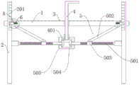
Fig. 1 is a schematic structural view of a foot rest for green decoration construction provided by the utility model;
fig. 2 is a top view of a foot rest for green decoration construction provided by the utility model;
FIG. 3 is an enlarged view of FIG. 1 at A;
FIG. 4 is an enlarged view of FIG. 2 at B;
FIG. 5 is an assembly view of the first bevel gear and the second bevel gear of the present invention;
fig. 6 is an assembly view of the middle slider and the clamping block of the present invention.
Illustration of the drawings:
1. a support plate; 2. a support bar; 201. a card slot; 3. an anti-slip bump; 4. an L-shaped drive rod; 401. a first bevel gear; 5. an adjustment assembly; 501. a screw; 502. a transmission rod; 503. a threaded sleeve; 504. a second bevel gear; 505. a mounting frame; 6. locking the assembly; 601. a clamping block; 602. a compression spring; 603. an L-shaped opening; 604. a slider; 605. a chute.
Detailed Description
The technical solutions in the embodiments of the present invention will be described clearly and completely with reference to the accompanying drawings in the embodiments of the present invention, and it is obvious that the described embodiments are only some embodiments of the present invention, not all embodiments.
Referring to fig. 1 to 6, a foot rest for green finishing construction includes a support plate 1 and an adjustment assembly 5;
the supporting rods 2 are movably penetrated through the corners of the supporting plate 1, the mounting frame 505 is arranged at the center of the bottom of the supporting plate 1, the first bevel gear 401 is rotatably arranged inside the mounting frame 505, the L-shaped driving rod 4 is movably penetrated through the middle part of the supporting plate 1, and the bottom end of the L-shaped driving rod 4 penetrates through the mounting frame 505 and is connected with the first bevel gear 401;
the adjusting assembly 5 comprises a plurality of screw rods 501 and a plurality of transmission rods 502, a plurality of second bevel gears 504 are meshed and connected to the first bevel gears 401, the plurality of screw rods 501 are respectively rotatably connected to the corresponding support rods 2, the end portions of the screw rods 501 penetrate through the mounting frame 505 and are connected to the corresponding second bevel gears 504, threaded sleeves 503 are sleeved on the screw rods 501 in a threaded manner, the plurality of transmission rods 502 are respectively hinged to the corresponding threaded sleeves 503, and the top ends of the transmission rods 502 are hinged to the bottom sides of the support plates 1.
The mounting bracket 505 is used for limiting the L-shaped driving rod 4 by the mounting bracket 505, so that the first bevel gear 401 at the bottom end of the L-shaped driving rod 4 can not be disengaged from the second bevel gear 504 when the L-shaped driving rod 4 rotates.
When the staff stands on the backup pad 1, when needing to adjust the height of backup pad 1, L shape actuating lever 4 is rotated to the positive direction, L shape actuating lever 4 rotates and drives first bevel gear 401 and rotate, first bevel gear 401 drives a plurality of second bevel gears 504 and rotates in step, second bevel gear 504 drives screw rod 501 and rotates, screw rod 501 rotates, make swivel nut 503 take place to remove on screw rod 501, swivel nut 503 drives transfer line 502 and removes, a plurality of transfer lines 502 synchronous motion drives backup pad 1 rebound, thereby backup pad 1 is holding in the palm the staff rebound on the backup pad 1.
Also comprises a locking assembly 6; the locking assembly 6 comprises a clamping block 601 and a compression spring 602, a sliding groove 605 is formed in the inner wall of the rectangular opening of the support plate 1, the inner wall of the rectangular opening is used for penetrating through the support rod 2, the clamping block 601 is arranged in the sliding groove 605 in a sliding mode, a plurality of clamping grooves 201 are formed in the support rod 2 at equal intervals, the clamping block 601 is matched with the clamping grooves 201, and two ends of the compression spring 602 are connected with the inner walls of the clamping block 601 and the sliding groove 605 respectively.
The end of the latch 601 is a ramp.
An L-shaped opening 603 communicated with the sliding groove 605 is formed in the supporting plate 1, a sliding block 604 is arranged in the L-shaped opening 603 in a sliding mode, and the sliding block 604 is connected with the clamping block 601 in a sliding mode.
When the support plate 1 moves upwards, the end face of the fixture block 601 is an inclined face, so that the support plate 1 can drive the fixture block 601 to move upwards, the compression spring 602 is compressed and reset in the process that the fixture block 601 moves upwards, the fixture block 601 is separated from and clamped with the clamping groove 201, when the support plate 1 moves upwards to a proper position, the support plate 1 drives the fixture block 601 to be clamped with the clamping groove 201, a plurality of fixture blocks 601 replace the transmission rod 502 to support the support plate 1, the bearing of the transmission rod 502 is reduced, and the transmission rod 502 is not easy to damage;
when the support plate 1 needs to move downwards, the fixture block 601 clamped with the clamping groove 201 is firstly pulled out of the clamping groove 201, the compression spring 602 is stressed to compress, then the sliding block 604 is slid to clamp the sliding block 604 with the vertical end of the L-shaped opening 603, so that the fixture block 601 is limited and is not moved due to the elasticity of the compression spring 602, the L-shaped driving rod 4 is rotated in the opposite direction, and similarly, the support plate 1 moves downwards, when the support plate 1 reaches a specified height, the sliding block 604 is slid to separate the sliding block 604 from the vertical end of the L-shaped opening 603, the compression spring 602 is reset under the elasticity of the compression spring 602, the compression spring 602 pushes the fixture block 601 to clamp the corresponding clamping groove 201, and therefore, the downwards movement adjustment of the support plate 1 is completed.
The top surface of the supporting plate 1 is provided with a plurality of anti-skid lugs 3.
The anti-skid lugs 3 are used for increasing the friction force between the vamps of the workers on the support plate 1 and the support plate 1, so that the anti-skid effect is achieved, and the workers are safer during construction.
The above, only be the concrete implementation of the preferred embodiment of the present invention, but the protection scope of the present invention is not limited thereto, and any person skilled in the art is in the technical scope of the present invention, according to the technical solution of the present invention and the utility model, the concept of which is equivalent to replace or change, should be covered within the protection scope of the present invention.
Claims (5)
1. The utility model provides a foot rest for green fitment construction which characterized in that includes: a support plate (1) and an adjustment assembly (5);
supporting rods (2) are movably arranged at the corners of the supporting plate (1) in a penetrating mode, an installation frame (505) is arranged at the center of the bottom of the supporting plate (1), a first bevel gear (401) is rotatably arranged inside the installation frame (505), an L-shaped driving rod (4) is movably arranged in the middle of the supporting plate (1) in a penetrating mode, and the bottom end of the L-shaped driving rod (4) penetrates through the installation frame (505) and is connected with the first bevel gear (401);
the adjusting assembly (5) comprises a plurality of screw rods (501) and a plurality of transmission rods (502), a plurality of second bevel gears (504) are connected to the first bevel gears (401) in a meshed mode, the screw rods (501) are respectively connected with the corresponding supporting rods (2) in a rotating mode, the end portions of the screw rods (501) penetrate through the mounting frame (505) and are connected with the corresponding second bevel gears (504), threaded sleeves (503) are sleeved on the screw rods (501) in a threaded mode, the transmission rods (502) are hinged to the corresponding threaded sleeves (503), and the top ends of the transmission rods (502) are hinged to the bottom side of the supporting plate (1).
2. A foot rest for green finishing construction as claimed in claim 1, further comprising a locking assembly (6); the locking assembly (6) comprises a clamping block (601) and a compression spring (602), a sliding groove (605) is formed in the inner wall of a rectangular opening, which is used for penetrating through the supporting rod (2), of the supporting plate (1), the clamping block (601) is arranged in the sliding groove (605) in a sliding mode, a plurality of clamping grooves (201) are formed in the supporting rod (2) at equal intervals, the clamping block (601) is matched with the clamping grooves (201), and two ends of the compression spring (602) are connected with the inner walls of the clamping block (601) and the sliding groove (605) respectively.
3. A foot rest for green finishing construction as claimed in claim 2, wherein the end of the clip (601) is a slope.
4. A foot stool for green decoration construction according to claim 1, characterized in that, the support plate (1) is provided with an L-shaped opening (603) communicated with the sliding groove (605), the L-shaped opening (603) is provided with a sliding block (604) in a sliding manner, and the sliding block (604) is connected with the clamping block (601) in a sliding manner.
5. A foot rest for green finishing construction according to claim 1, characterized in that the top surface of the support plate (1) is provided with a plurality of anti-slip projections (3).
Priority Applications (1)
| Application Number | Priority Date | Filing Date | Title |
|---|---|---|---|
| CN202120007943.2U CN214995755U (en) | 2021-01-05 | 2021-01-05 | A foot rest for green fitment construction |
Applications Claiming Priority (1)
| Application Number | Priority Date | Filing Date | Title |
|---|---|---|---|
| CN202120007943.2U CN214995755U (en) | 2021-01-05 | 2021-01-05 | A foot rest for green fitment construction |
Publications (1)
| Publication Number | Publication Date |
|---|---|
| CN214995755U true CN214995755U (en) | 2021-12-03 |
Family
ID=79143017
Family Applications (1)
| Application Number | Title | Priority Date | Filing Date |
|---|---|---|---|
| CN202120007943.2U Active CN214995755U (en) | 2021-01-05 | 2021-01-05 | A foot rest for green fitment construction |
Country Status (1)
| Country | Link |
|---|---|
| CN (1) | CN214995755U (en) |
-
2021
- 2021-01-05 CN CN202120007943.2U patent/CN214995755U/en active Active
Similar Documents
| Publication | Publication Date | Title |
|---|---|---|
| CN112975675A (en) | Wood system connecting tenon preparation system of processing | |
| CN214995755U (en) | A foot rest for green fitment construction | |
| CN210683119U (en) | Lifting frame convenient to adjust for building | |
| CN209876328U (en) | Height increasing bracket for jack | |
| CN111877719A (en) | Scaffold for construction convenient to aggregate erection | |
| CN217233383U (en) | Hydraulic engineering overhauls cat ladder | |
| CN214575999U (en) | Assembled building bearing structure | |
| CN214061941U (en) | Liftable steel structure frame | |
| CN219175780U (en) | Green's auxiliary device is laid with ceramic tile to interior decoration | |
| CN212450250U (en) | Special lifting appliance for outdoor construction of transformer substation | |
| CN204152417U (en) | A kind of removable hanging ladder | |
| CN213015683U (en) | Adjustable electronic communication tower convenient to installation | |
| CN211007704U (en) | Template hoisting device for building | |
| CN110902624B (en) | Indoor high-altitude installation working device and using method thereof | |
| CN112267673A (en) | Aluminum template connecting and fixing mechanism for civil engineering | |
| CN111633797A (en) | Prefabricated plate napping device | |
| CN211313291U (en) | Indoor outer decoration is with device of ascending a height | |
| CN211473328U (en) | Protective hanging basket for continuous beam construction | |
| CN218539002U (en) | Various steel sheet construction installation hoist and mount frame with prevent empting function | |
| CN213927510U (en) | Aluminum template connecting and fixing mechanism for civil engineering | |
| CN216196460U (en) | Cat ladder for construction | |
| CN212388918U (en) | Lifting type self-stabilizing building equipment | |
| CN217203706U (en) | Warning fence based on construction engineering construction site | |
| CN220725164U (en) | Assembled building foundation skeleton texture | |
| CN220117700U (en) | Building construction builds current frame of jumping fast |
Legal Events
| Date | Code | Title | Description |
|---|---|---|---|
| GR01 | Patent grant | ||
| GR01 | Patent grant |