CN210683119U - Lifting frame convenient to adjust for building - Google Patents
Lifting frame convenient to adjust for building Download PDFInfo
- Publication number
- CN210683119U CN210683119U CN201921325446.6U CN201921325446U CN210683119U CN 210683119 U CN210683119 U CN 210683119U CN 201921325446 U CN201921325446 U CN 201921325446U CN 210683119 U CN210683119 U CN 210683119U
- Authority
- CN
- China
- Prior art keywords
- fixedly connected
- building
- adjust
- convenient
- rod
- Prior art date
- Legal status (The legal status is an assumption and is not a legal conclusion. Google has not performed a legal analysis and makes no representation as to the accuracy of the status listed.)
- Expired - Fee Related
Links
Images


Landscapes
- Ladders (AREA)
Abstract
The utility model provides a crane convenient to adjust for building, which comprises a fixed base, the top both sides fixed mounting of fixing base has the mount, the spout has been seted up to one side symmetry of mount, the inside fixedly connected with slide bar of mount, the slider has been cup jointed on the surface of slide bar, is located compression spring has been cup jointed on the slide bar of slider bottom, compression spring's one end fixed connection is at the upper surface of fixing base, the top fixedly connected with spliced pole of slider, the top fixedly connected with workstation of spliced pole. This for building is convenient for adjust the lifter when rotating the carousel, upwards pulls up the pin rod for the pin rod breaks away from the first through-hole of positioning disk, and after the adjustment height was accomplished, unclamps the pin rod, makes the pin rod insert first through-hole, is favorable to the location to the carousel, avoids the carousel to rotate, makes the workstation fix at corresponding height, and convenient operation is swift, and labour saving and time saving has guaranteed the safety of construction simultaneously.
Description
Technical Field
The utility model relates to a building technical field specifically is a crane convenient to adjust for building.
Background
Along with the development of the society, the construction industry is also developed vigorously, the variety of some auxiliary machinery in the construction industry is more and more, the construction machinery is a general name of mechanical equipment used for engineering construction and urban and rural construction, the construction machinery is also called as construction machinery, engineering machinery and the like in China, and in the construction auxiliary mechanical equipment, a lifting frame serving as one of the auxiliary machinery is the most common, and the lifting frame is a working platform which is erected for ensuring the smooth proceeding of each construction process.
The crane is convenient to use, and simple structure receives liking of master workers deeply in the construction of building, but the crane among the prior art when needs increase the height, is not convenient for increase the height, needs the worker people to set up and adds the height, and not only work efficiency is low like this, wastes a large amount of manpowers moreover, causes the potential safety hazard easily.
SUMMERY OF THE UTILITY MODEL
Technical problem to be solved
Not enough to prior art, the utility model provides a crane for building be convenient for adjust has solved the problem of mentioning in the above background art.
(II) technical scheme
In order to achieve the above purpose, the utility model discloses a following technical scheme realizes: a lifting frame convenient to adjust for buildings comprises a fixed seat, wherein fixed frames are fixedly arranged on two sides of the top of the fixed seat, sliding grooves are symmetrically formed in one side of each fixed frame, a sliding rod is fixedly connected inside each fixed frame, a sliding block is sleeved on the surface of the sliding rod, a compression spring is sleeved on the sliding rod positioned at the bottom of the sliding block, one end of each compression spring is fixedly connected to the upper surface of the fixed seat, a connecting column is fixedly connected to the top of the sliding block, a workbench is fixedly connected to the top of the connecting column, a supporting frame is fixedly arranged on one side of the workbench, a positioning disc is fixedly arranged on the top of the supporting frame, a plurality of first through holes are formed in the positioning disc, a bearing is sleeved at the middle position of the positioning disc, a threaded rod is movably connected to the bearing, a rotary disc is fixedly connected to, the surface of the turntable is provided with a second through hole, a pin rod is inserted in the second through hole, one side of the surface of the connecting column is fixedly connected with a cross rod, and one side of the cross rod is fixedly connected with a thread block.
Preferably, one end of the sliding block is fixedly connected with a fixing rod, and one end of the fixing rod is fixedly provided with a pulley.
Preferably, the surface of the workbench is provided with anti-skid lines, and guard rails are fixedly mounted around the workbench.
Preferably, one side of the workbench is fixedly connected with a vertical ladder.
Preferably, one end of the threaded rod is fixedly connected with a limiting plate.
Preferably, a hydraulic rod is fixedly mounted at the bottom of the fixed seat, and a universal wheel is fixedly mounted at one side of the bottom of the fixed seat, which is located on the hydraulic rod.
(III) advantageous effects
The utility model provides a crane convenient to adjust for building. Has the following beneficial effects:
1. the dwang through rotating the setting drives the carousel and rotates, the carousel drives the threaded rod and rotates, make the fillet of thread realize reciprocating on the threaded rod, the fillet of thread drives the horizontal pole, spliced pole and slide bar reciprocate on the slide bar, thereby make the workstation rise, the slider of setting moves on the slide bar, the stability that the workstation goes up and down has been guaranteed, the dead lever and the pulley of setting reduce friction when making the lift, it is more laborsaving, the slider bottom sets up compression spring and gives thrust when the workstation rises, when descending, play the cushioning effect, the security of using is improved.
2. Vertical ladder through setting up is convenient from top to bottom in the master worker, in the rotation carousel, upwards pull up the pin rod, make the pin rod break away from the first through-hole of positioning disk, after the adjustment height is accomplished, loosen the pin rod, make the pin rod insert in first through-hole, be favorable to the location to the carousel, avoid the carousel to rotate, make the workstation fix at corresponding height, the universal wheel of setting is convenient to move it to the position of use, and lock it, according to the topography needs when using the device, raise its hydraulic stem, make the device leveling, guarantee it steadily, guarantee the safety of master worker's construction.
Drawings
Fig. 1 is a front view of the present invention;
fig. 2 is a top view of the present invention;
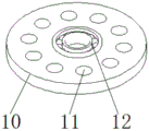
FIG. 3 is a structural diagram of the positioning plate of the present invention;
fig. 4 is an enlarged view of a portion a of fig. 1 according to the present invention;
fig. 5 is a structural view of the fixing frame of the present invention.
In the figure: the device comprises a fixed seat 1, a fixed frame 2, a sliding chute 3, a sliding rod 4, a sliding block 5, a compression spring 6, a connecting column 7, a workbench 8, a supporting frame 9, a positioning disc 10, a first through hole 11, a bearing 12, a threaded rod 13, a rotating disc 14, a rotating rod 15, a second through hole 16, a pin rod 17, a cross rod 18, a threaded block 19, a fixed rod 20, a pulley 21, an anti-skid thread 22, a protective guard 23, a vertical ladder 24, a limiting plate 25, a hydraulic rod 26 and a universal wheel 27.
Detailed Description
The invention is explained in more detail below with reference to the figures and examples.
The embodiment of the utility model provides a crane for building is convenient for adjust, as shown in figure 1-5, including fixing base 1, fixing frame 2 is fixedly installed on both sides of the top of fixing base 1, the installed fixing frame 2 is used for connecting slide block 5, etc., indirect is used for supporting workbench 8, one side of fixing frame 2 is symmetrically provided with slide groove 3, the inside of fixing frame 2 is fixedly connected with slide bar 4, slide block 5 is sleeved on the surface of slide bar 4, compression spring 6 is sleeved on slide bar 4 at the bottom of slide block 5, one end of compression spring 6 is fixedly connected on the upper surface of fixing base 1, slide groove 3 arranged on fixing frame 2 is used for the orbit of pulley 21, slide block 5 arranged inside of fixing frame 2 moves on slide bar 4, the stability of the lifting of workbench 8 is ensured, compression spring 6 arranged at the bottom of slide block 5 gives thrust when workbench 8 rises, when the device descends, the buffer effect is achieved, the use safety of the device is improved, a connecting column 7 is fixedly connected to the top of a sliding block 5, a workbench 8 is fixedly connected to the top of the connecting column 7, the workbench 8 is used for the range of movement of teachers and masters of workers, a support frame 9 is fixedly installed on one side of the workbench 8, a positioning disc 10 is fixedly installed on the top of the support frame 9, a plurality of first through holes 11 are formed in the positioning disc 10, a bearing 12 is sleeved on the middle position of the positioning disc 10, a threaded rod 13 is movably connected to the bearing 12, a rotary disc 14 is fixedly connected to one end of the threaded rod 13, a rotary rod 15 is fixedly connected to one side of the top of the rotary disc 14, a second through hole 16 is formed in the surface of the rotary disc 14, a pin rod 17 is inserted in the second through hole 16, the support frame 9 is used for installing the positioning disc 10, the first through hole 11 formed in the positioning disc 10, guarantee that it does not take place to reciprocate when rotating, the carousel 14 and the dwang 15 that set up are used for driving threaded rod 13, the second through-hole 16 that sets up on carousel 14 is used for pegging graft round pin rod 17, round pin rod 17 can peg graft to the first through-hole 11 of positioning disk 10 simultaneously, it is fixed with threaded rod 13, do not let it take place to rotate, the height of workstation has been guaranteed to be certain, surface one side fixedly connected with horizontal pole 18 of spliced pole 7, one side fixedly connected with thread block 19 of horizontal pole 18, the thread block 19 of setting makes when threaded rod 13 rotates, thread block 19 removes along threaded rod 13, drive horizontal pole 18 and spliced pole 7 and reciprocate, and then realize workstation 8's raising and lowering functions.
Specifically, the one end fixedly connected with dead lever 20 of slider 5, the one end fixed mounting of dead lever 20 has pulley 21, and the dead lever 20 and the pulley 21 that set up remove in spout 3 for reduce the friction during the lift, lift the device more laborsaving.
Specifically, the surface of workstation 8 is provided with anti-skidding line 22, and workstation 8 fixed mounting has rail guard 23 all around, sets up anti-skidding line 22 and prevents that master workers from slipping to fall down, and rail guard 23 prevents that use tools and master workers from falling down, guarantees the security of during operation.
Specifically, one side fixedly connected with of workstation 8 erects ladder 24, and this crane about the workman of being convenient for is erected ladder 24 in the installation, guarantees that its safety has save time.
Specifically, one end of the threaded rod 13 is fixedly connected with a limiting plate 25, and one end of the threaded rod 13 is fixedly connected with the limiting plate 25 to prevent the threaded block 19 from sliding out of the threaded rod 13.
Specifically, the bottom fixed mounting of fixing base 1 has hydraulic stem 26, and one side fixed mounting that the bottom of fixing base 1 is located hydraulic stem 26 has universal wheel 27, and the universal wheel 27 of setting conveniently moves it to the position of use to lock it, according to the topography needs when using the device, rise its hydraulic stem 26, make the device leveling, guarantee its steadily, guarantee the safety of master worker's construction.
The working principle is as follows: when the device is in use, it is moved to the use position, the universal wheels 27 are locked, the hydraulic rods 26 of the device are lifted according to the terrain requirements, the device is leveled and is ensured to be stable, the working platform 8 is ascended through the vertical ladder 24, when the height needs to be adjusted, the pin 17 is pulled upwards, so that the pin 17 is separated from the first through hole 11 of the positioning disk 10, the rotating rod 15 is rotated to drive the rotating disk 14 to rotate, the rotating disk 14 drives the threaded rod 13 to rotate, the threaded rod 13 rotates and simultaneously enables the threaded block 19 to move up and down, the threaded block 19 drives the cross rod 18, the connecting column 7 and the sliding block 5 to move along the sliding rod 4, thereby driving the worktable 8 to move, and when the height adjustment is completed, the pin rod 17 is loosened, so that the pin rod 17 is inserted into the first through hole 11, the positioning of the rotary table 14 is facilitated, the rotary table 14 is prevented from rotating, and the workbench 8 is fixed at a corresponding height.
Although embodiments of the present invention have been shown and described, it will be appreciated by those skilled in the art that changes, modifications, substitutions and alterations can be made in these embodiments without departing from the principles and spirit of the invention, the scope of which is defined in the appended claims and their equivalents.
Claims (6)
1. The utility model provides a crane for building be convenient for adjust, includes fixing base (1), its characterized in that: the fixing device is characterized in that fixing frames (2) are fixedly mounted on two sides of the top of the fixing base (1), sliding grooves (3) are symmetrically formed in one side of each fixing frame (2), a sliding rod (4) is fixedly connected to the inside of each fixing frame (2), a sliding block (5) is sleeved on the surface of each sliding rod (4), a compression spring (6) is sleeved on each sliding rod (4) at the bottom of each sliding block (5), one end of each compression spring (6) is fixedly connected to the upper surface of the corresponding fixing base (1), a connecting column (7) is fixedly connected to the top of each sliding block (5), a workbench (8) is fixedly connected to the top of each connecting column (7), a supporting frame (9) is fixedly mounted on one side of each workbench (8), a positioning disc (10) is fixedly mounted on the top of each supporting frame (9), and a plurality of first through holes, bearing (12) have been cup jointed to the intermediate position of positioning disk (10), swing joint has threaded rod (13) on bearing (12), one end fixedly connected with carousel (14) of threaded rod (13), top one side fixedly connected with dwang (15) of carousel (14), second through-hole (16) have been seted up on the surface of carousel (14), it has cotter (17) to peg graft in second through-hole (16), surface one side fixedly connected with horizontal pole (18) of spliced pole (7), one side fixedly connected with thread block (19) of horizontal pole (18).
2. The crane convenient to adjust for building of claim 1, wherein: one end fixedly connected with dead lever (20) of slider (5), the one end fixed mounting of dead lever (20) has pulley (21).
3. The crane convenient to adjust for building of claim 1, wherein: the surface of workstation (8) is provided with anti-skidding line (22), fixed mounting has rail guard (23) around workstation (8).
4. The crane convenient to adjust for building of claim 1, wherein: one side of the working table (8) is fixedly connected with a vertical ladder (24).
5. The crane convenient to adjust for building of claim 1, wherein: one end of the threaded rod (13) is fixedly connected with a limiting plate (25).
6. The crane convenient to adjust for building of claim 1, wherein: the hydraulic rod (26) is fixedly installed at the bottom of the fixing seat (1), and the universal wheel (27) is fixedly installed on one side, located on the hydraulic rod (26), of the bottom of the fixing seat (1).
Priority Applications (1)
| Application Number | Priority Date | Filing Date | Title |
|---|---|---|---|
| CN201921325446.6U CN210683119U (en) | 2019-08-15 | 2019-08-15 | Lifting frame convenient to adjust for building |
Applications Claiming Priority (1)
| Application Number | Priority Date | Filing Date | Title |
|---|---|---|---|
| CN201921325446.6U CN210683119U (en) | 2019-08-15 | 2019-08-15 | Lifting frame convenient to adjust for building |
Publications (1)
| Publication Number | Publication Date |
|---|---|
| CN210683119U true CN210683119U (en) | 2020-06-05 |
Family
ID=70892626
Family Applications (1)
| Application Number | Title | Priority Date | Filing Date |
|---|---|---|---|
| CN201921325446.6U Expired - Fee Related CN210683119U (en) | 2019-08-15 | 2019-08-15 | Lifting frame convenient to adjust for building |
Country Status (1)
| Country | Link |
|---|---|
| CN (1) | CN210683119U (en) |
Cited By (2)
| Publication number | Priority date | Publication date | Assignee | Title |
|---|---|---|---|---|
| CN112388533A (en) * | 2020-11-16 | 2021-02-23 | 浙江瑞昭科技股份有限公司 | Fastener with adjustable angle |
| CN114406750A (en) * | 2022-01-20 | 2022-04-29 | 漳州明德工贸有限公司 | Intelligent processing equipment and processing technology for lithium battery |
-
2019
- 2019-08-15 CN CN201921325446.6U patent/CN210683119U/en not_active Expired - Fee Related
Cited By (2)
| Publication number | Priority date | Publication date | Assignee | Title |
|---|---|---|---|---|
| CN112388533A (en) * | 2020-11-16 | 2021-02-23 | 浙江瑞昭科技股份有限公司 | Fastener with adjustable angle |
| CN114406750A (en) * | 2022-01-20 | 2022-04-29 | 漳州明德工贸有限公司 | Intelligent processing equipment and processing technology for lithium battery |
Similar Documents
| Publication | Publication Date | Title |
|---|---|---|
| CN210683119U (en) | Lifting frame convenient to adjust for building | |
| CN208428491U (en) | A kind of metope rail drilling mechanism with assist device | |
| CN215254391U (en) | Hanging flower basket is used to green building outer wall fitment | |
| CN108756743B (en) | Soil normal position direct pushing type sampling and restoring integrated drilling machine | |
| CN212581461U (en) | Lifting platform for housing construction | |
| CN215252954U (en) | Side slope supporting device for foundation engineering construction | |
| CN110893606A (en) | Hydraulic wrench lifting device | |
| CN205170321U (en) | Lifting platform | |
| CN214360123U (en) | Small-size lift is used in engineering construction | |
| CN212888292U (en) | Movable automatic lifting rack of drilling machine for reinforcing railway retaining wall | |
| CN214031553U (en) | Subway bogie lifting platform | |
| CN213710286U (en) | Adjustable scaffold | |
| CN212269375U (en) | Electromechanical device mounting frame | |
| CN211114707U (en) | Hydraulic template mounting tool | |
| CN112239185A (en) | Lifting device for electric power overhaul | |
| CN221295785U (en) | Adjustable elevator supporting device | |
| CN221220337U (en) | Crawling ladder for equipment overhaul of energy storage power station | |
| CN219217286U (en) | Lifting equipment for corridor | |
| CN214192459U (en) | Lamp cloth installation device | |
| CN212837608U (en) | Derrick for ultra-deep well drilling machine | |
| CN214246536U (en) | Scaffold convenient to move | |
| CN214197853U (en) | Cradle working height adjusting mechanism | |
| CN217439486U (en) | Scaffold for building construction for preventing slope collapse | |
| CN220926208U (en) | Automatic mechanical lifting equipment for building | |
| CN219489422U (en) | Inner climbing type tower crane |
Legal Events
| Date | Code | Title | Description |
|---|---|---|---|
| GR01 | Patent grant | ||
| GR01 | Patent grant | ||
| CF01 | Termination of patent right due to non-payment of annual fee | ||
| CF01 | Termination of patent right due to non-payment of annual fee |
Granted publication date: 20200605 Termination date: 20210815 |