CN214966041U - Incision traction device for orthopedic surgery - Google Patents
Incision traction device for orthopedic surgery Download PDFInfo
- Publication number
- CN214966041U CN214966041U CN202120336505.0U CN202120336505U CN214966041U CN 214966041 U CN214966041 U CN 214966041U CN 202120336505 U CN202120336505 U CN 202120336505U CN 214966041 U CN214966041 U CN 214966041U
- Authority
- CN
- China
- Prior art keywords
- worm
- plates
- rotating
- servo motor
- traction device
- Prior art date
- Legal status (The legal status is an assumption and is not a legal conclusion. Google has not performed a legal analysis and makes no representation as to the accuracy of the status listed.)
- Expired - Fee Related
Links
- 230000000399 orthopedic effect Effects 0.000 title claims abstract description 19
- 238000001356 surgical procedure Methods 0.000 title claims abstract description 19
- 230000007246 mechanism Effects 0.000 claims abstract description 11
- 238000005286 illumination Methods 0.000 claims 1
- 238000012829 orthopaedic surgery Methods 0.000 claims 1
- 230000000474 nursing effect Effects 0.000 description 2
- 238000006467 substitution reaction Methods 0.000 description 2
- 230000004075 alteration Effects 0.000 description 1
- 210000003484 anatomy Anatomy 0.000 description 1
- 230000009286 beneficial effect Effects 0.000 description 1
- 210000000988 bone and bone Anatomy 0.000 description 1
- 230000006378 damage Effects 0.000 description 1
- 238000001804 debridement Methods 0.000 description 1
- 201000010099 disease Diseases 0.000 description 1
- 208000037265 diseases, disorders, signs and symptoms Diseases 0.000 description 1
- 238000006073 displacement reaction Methods 0.000 description 1
- 229940079593 drug Drugs 0.000 description 1
- 239000003814 drug Substances 0.000 description 1
- 238000009413 insulation Methods 0.000 description 1
- 238000000034 method Methods 0.000 description 1
- 230000004048 modification Effects 0.000 description 1
- 238000012986 modification Methods 0.000 description 1
- 210000000056 organ Anatomy 0.000 description 1
- 230000001575 pathological effect Effects 0.000 description 1
- 230000007170 pathology Effects 0.000 description 1
- 238000000053 physical method Methods 0.000 description 1
- 230000035479 physiological effects, processes and functions Effects 0.000 description 1
- 230000008439 repair process Effects 0.000 description 1
- 210000002027 skeletal muscle Anatomy 0.000 description 1
- 210000002435 tendon Anatomy 0.000 description 1
- 210000001519 tissue Anatomy 0.000 description 1
- 230000000472 traumatic effect Effects 0.000 description 1
Images


Abstract
The utility model discloses an incision traction device for orthopedic surgery, which relates to the field of orthopedic surgery equipment and comprises two supporting plates, a fixed plate and a movable plate, wherein the bottom end of the fixed plate is provided with two fixed blocks which are symmetrically distributed, a first worm and two sliding rods are fixedly arranged between the two fixed blocks, the top end of the movable plate is provided with two rotating plates, a second worm is arranged between the two rotating plates and is spirally matched and connected with the first worm, the bottom end of the movable plate is provided with a rotating motor, the output end of the rotating motor is provided with a gear, the movable plate is also provided with a rotating disk which is rotatably connected, the side wall of the rotating disk is provided with a rack, the rack is meshed and connected with the gear, the rotating disk is provided with a fixed box, a clamping mechanism is arranged in the fixed box, the utility model reduces the labor force for medical care, the medical staff is convenient to carry out the traction work of the incision, and the working efficiency is increased.
Description
Technical Field
The utility model relates to the field of orthopedic surgery equipment, in particular to an incision traction device for orthopedic surgery.
Background
Orthopedics is one of the most common departments in various hospitals, mainly studies the anatomy, physiology and pathology of the skeletal muscle system, and maintains and develops the normal form and function of the system by using medicines, operations and physical methods, and the orthopedic operation is the main treatment method of surgery. Aims to cure or diagnose diseases, such as removing pathological tissues, repairing injuries, transplanting organs, improving the functions and the shapes of bodies, and the like.
Orthopedic surgery generally divide into the level four, and the level one operation is debridement art, and the level two operation is traumatic tendon repair art, and the tertiary operation is internal fixation of fracture etc. and the level four is for mainly referring to the operation at cervical vertebra position, and the higher incision of operation is great darker to the level, and simple centre gripping is taken off the words, and the quality and the efficiency of performing the operation for a long time can greatly reduced, and current draw gear is inconvenient many and pulls the incision of incision length overlength, can not follow the angle and the size of incision and carry out appropriate traction adjustment to the incision.
SUMMERY OF THE UTILITY MODEL
The utility model aims to provide an incision traction device for orthopedic surgery to solve the problems in the background technology,
in order to achieve the above object, the utility model provides a following technical scheme:
an incision traction device for orthopedic surgery comprises four electric telescopic rods, two supporting plates, a fixed plate, a first servo motor and a movable plate, wherein the two supporting plates are fixedly connected with the fixed plate, the four electric telescopic rods are respectively distributed at the bottom ends of the two supporting plates, the bottom end of the fixed plate is symmetrically provided with two fixed blocks, a first worm and two sliding rods are fixedly arranged between the two fixed blocks, the top end of the movable plate is provided with two rotating plates, sliding holes are formed in the two rotating plates, the two sliding holes are respectively in sliding connection with the two sliding rods, a second worm is arranged between the two rotating plates, one end of the second worm penetrates through one of the rotating plates to be fixedly connected with the output end of the first servo motor, and the second worm is in spiral fit connection with the first worm, the bottom of movable plate is provided with the rotating electrical machines, the output of rotating electrical machines is provided with the gear, still be provided with the rotary disk that rotates the connection on the movable plate, be provided with the rack on the lateral wall of rotary disk, the rack is connected with the gear engagement, be provided with the fixed case on the rotary disk, the bottom of fixed case is provided with logical groove, be provided with clamping mechanism in the fixed case.
On the basis of the technical scheme, the utility model discloses still provide following optional technical scheme:
in one alternative: the movable plates are two and are respectively connected with the two sliding rods in a sliding mode.
In one alternative: clamping mechanism includes second servo motor, threaded rod, two clamp plates, the fixed one end that sets up at the set bin of second servo motor, the both sides screw thread direction of threaded rod, the one end of threaded rod and second servo motor's output fixed connection, two the top and the threaded rod looks screw fit of clamp plate are connected, two clamp plates all with the lateral wall sliding connection who leads to the groove.
In one alternative: and illuminating lamps are arranged on two sides of the through groove.
In one alternative: one of them the top of backup pad is provided with the control button box, the control button box is connected with four electric telescopic handle, the equal electric property of first servo motor and rotating electrical machines.
In one alternative: the first worm and the second worm form an angle of 90 degrees, and the lead angle of the threads is 45 degrees.
Compared with the prior art, the beneficial effects of the utility model are as follows:
the utility model discloses incision draw gear for orthopedic surgery drives the movable plate through the interact of the first worm that sets up, first servo motor and second worm and moves on first worm, rotates through the clamping mechanism of the fixed incasement on the electric rotary disk of rotating electrical machines simultaneously, and the convenience is drawn the incision of different angles and size, and realizes the adjustment at any time to the incision size through the clamping mechanism on two movable plates that set up, the utility model discloses reduce medical and nursing's labour, made things convenient for medical personnel to carry out notched traction work, increased work efficiency.
Drawings
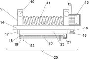
Fig. 1 is a schematic structural view of the incision traction device for orthopedic surgery of the present invention.
Fig. 2 is a schematic view of the bottom structure of the middle fixing plate of the present invention.
Fig. 3 is a schematic side view of the middle moving plate of the present invention.
Fig. 4 is a schematic bottom view of the fixing box of the present invention.
Notations for reference numerals: the device comprises an electric telescopic rod 1, a supporting rod 2, a fixing plate 3, a control button box 4, a light strip 5, a fixing block 6, a sliding rod 7, a first worm 8, a rotating plate 9, a sliding hole 10, a second worm 11, a first servo motor 12, a sound insulation box 13, a moving plate 14, a rotating motor 15, a gear 16, a rack 17, a fixing box 18, a through groove 19, a threaded rod 20, a second servo motor 21, a clamping plate 22, a rotating disc 23, a lighting lamp 24 and a clamping mechanism 25.
Detailed Description
The present invention will be described in detail with reference to the following embodiments, wherein like or similar elements are designated by like reference numerals throughout the drawings or description, and wherein the shape, thickness or height of the various elements may be expanded or reduced in practical applications. The embodiments of the present invention are provided only for illustration, and not for limiting the scope of the present invention. Any obvious and obvious modifications or alterations to the present invention can be made without departing from the spirit and scope of the present invention.
Example 1
Referring to fig. 1 to 4, in an embodiment of the present invention, an incision traction device for orthopedic surgery includes four electric telescopic rods 1, two supporting plates 2, a fixed plate 3, a first servo motor 12, and a moving plate 14, two of the supporting plates 2 are fixedly connected to the fixed plate 3, four electric telescopic rods 1 are respectively disposed at the bottom ends of the two supporting plates 2, two fixed blocks 6 are disposed at the bottom end of the fixed plate 3, a first worm 8 and two sliding rods 7 are fixedly disposed between the two fixed blocks 6, two rotating plates 9 are disposed at the top end of the moving plate 14, sliding holes 10 are disposed on the two rotating plates 9, the two sliding holes 10 are respectively slidably connected to the two sliding rods 7, a second worm 11 is disposed between the two rotating plates 9, one end of the second worm 11 passes through one of the rotating plates 9 and is fixedly connected to an output end of the first servo motor 12, the second worm 11 is spirally matched and connected with the first worm 8, a rotating motor 15 is arranged at the bottom end of the moving plate 14, a gear 16 is arranged at the output end of the rotating motor 15, a rotating disc 23 which is rotatably connected with the moving plate 14 is further arranged on the moving plate 14, a rack 17 is arranged on the side wall of the rotating disc 23, the rack 17 is meshed and connected with the gear 16, a fixed box 18 is arranged on the rotating disc 23, a through groove 19 is arranged at the bottom end of the fixed box 18, and a clamping mechanism 25 is arranged in the fixed box 18;
moving plate 14 is two and equally divide do not with two slide bar 7 sliding connection, clamping mechanism 25 includes second servo motor 21, threaded rod 20, two clamp plates 22, the fixed one end that sets up at fixed case 18 of second servo motor 21, the both sides screw thread direction of threaded rod 20, the one end of threaded rod 20 and the output fixed connection of second servo motor 21, two the top and the threaded rod 20 of clamp plate 22 are connected with the screw-thread fit mutually, two clamp plates 22 all with the lateral wall sliding connection who leads to groove 19, it all is provided with light 24 to lead to groove 19 both sides, makes the doctor observe the clarity that the wound can be more, one of them the top of backup pad 2 is provided with control button box 4, control button box 4 is connected with four electric telescopic handle 1, first servo motor 12 and the equal electrical property of rotating electrical machines 15, conveniently controls whole device first worm 8 and second worm 11 are angle of 90 degrees and threaded leading title angle is 45 degrees And the utility model discloses reduce medical and nursing's labour, made things convenient for medical personnel to carry out notched traction work, increased work efficiency.
The utility model discloses a theory of operation is: when using the utility model discloses carry out the notched work of pulling of bone surgery, prevent earlier whole device in notched upper end, then start four electric telescopic handle 1 and make fixed plate 3 go up and down to suitable position, then start rotating electrical machines 15, make gear 16 be connected with the meshing of rack 17, it constructs to suitable position to drive clamping mechanism 24, then start first servo motor 12 and drive second worm 11 and first worm 8 meshing connection, then drive movable plate 14 and slide to notched positive upper end along slide bar 7, then start second servo motor 21 and drive threaded rod 20 and rotate, drive another clamp plate 22 mutual displacement simultaneously, the realization is to notched pulling.
Example 2
Referring to fig. 2, the present embodiment is different from embodiment 1 in that a plurality of light bars 5 are disposed on a bottom end surface of the fixing plate 3, and medical staff can observe the incision position of a patient more conveniently through the light bars 5, so that the medical staff can use the device more conveniently.
The above description is only for the specific embodiments of the present disclosure, but the scope of the present disclosure is not limited thereto, and any person skilled in the art can easily conceive of the changes or substitutions within the technical scope of the present disclosure, and all the changes or substitutions should be covered within the scope of the present disclosure. Therefore, the protection scope of the present disclosure shall be subject to the protection scope of the claims.
Claims (6)
1. An incision traction device for orthopedic surgery comprises four electric telescopic rods (1), two supporting plates (2), a fixing plate (3), a first servo motor (12) and a moving plate (14), and is characterized in that the two supporting plates (2) are fixedly connected with the fixing plate (3), the four electric telescopic rods (1) are respectively distributed and arranged at the bottom ends of the two supporting plates (2), the bottom end of the fixing plate (3) is provided with two fixing blocks (6) which are symmetrically distributed, a first worm (8) and two sliding rods (7) are fixedly arranged between the two fixing blocks (6), the top end of the moving plate (14) is provided with two rotating plates (9), the two rotating plates (9) are respectively provided with sliding holes (10), the two sliding holes (10) are respectively in sliding connection with the two sliding rods (7), and a second worm (11) is arranged between the two rotating plates (9), the output fixed connection of one of them rotor plate (9) and first servo motor (12) is passed to the one end of second worm (11), second worm (11) and first worm (8) are connected in coordination mutually spirally, the bottom of movable plate (14) is provided with rotating electrical machines (15), the output of rotating electrical machines (15) is provided with gear (16), still be provided with on movable plate (14) and rotate rotary disk (23) of connecting, be provided with rack (17) on the lateral wall of rotary disk (23), rack (17) are connected with gear (16) meshing, be provided with on rotary disk (23) fixed case (18), the bottom of fixed case (18) is provided with logical groove (19), be provided with clamping mechanism (25) in fixed case (18).
2. Incision traction device for orthopaedic surgery according to claim 1, characterized in that said moving plates (14) are two and are each slidingly connected with two sliding rods (7), respectively.
3. The incision traction device for the orthopedic surgery, according to claim 1, characterized in that the clamping mechanism (25) comprises a second servo motor (21), a threaded rod (20), and two clamping plates (22), wherein the second servo motor (21) is fixedly disposed at one end of the fixed box (18), the threaded rod (20) has two side thread directions, one end of the threaded rod (20) is fixedly connected with the output end of the second servo motor (21), the top ends of the two clamping plates (22) are spirally connected with the threaded rod (20), and the two clamping plates (22) are both slidably connected with the side wall of the through slot (19).
4. Incision traction device for orthopedic surgery according to claim 3, characterized in that illumination lamps (24) are arranged on both sides of the through slot (19).
5. The incision traction device for orthopedic surgery according to claim 1, characterized in that a control button box (4) is arranged at the top end of one of the supporting plates (2), and the control button box (4) is electrically connected with four electric telescopic rods (1), the first servo motor (12) and the rotating motor (15).
6. Incision traction device for orthopedic surgery according to claim 1, characterized in that the first worm (8) and the second worm (11) are at an angle of 90 degrees and the thread lead angle is 45 degrees.
Priority Applications (1)
| Application Number | Priority Date | Filing Date | Title |
|---|---|---|---|
| CN202120336505.0U CN214966041U (en) | 2021-02-05 | 2021-02-05 | Incision traction device for orthopedic surgery |
Applications Claiming Priority (1)
| Application Number | Priority Date | Filing Date | Title |
|---|---|---|---|
| CN202120336505.0U CN214966041U (en) | 2021-02-05 | 2021-02-05 | Incision traction device for orthopedic surgery |
Publications (1)
| Publication Number | Publication Date |
|---|---|
| CN214966041U true CN214966041U (en) | 2021-12-03 |
Family
ID=79147083
Family Applications (1)
| Application Number | Title | Priority Date | Filing Date |
|---|---|---|---|
| CN202120336505.0U Expired - Fee Related CN214966041U (en) | 2021-02-05 | 2021-02-05 | Incision traction device for orthopedic surgery |
Country Status (1)
| Country | Link |
|---|---|
| CN (1) | CN214966041U (en) |
-
2021
- 2021-02-05 CN CN202120336505.0U patent/CN214966041U/en not_active Expired - Fee Related
Similar Documents
| Publication | Publication Date | Title |
|---|---|---|
| CN111227923A (en) | Fracture coaptation auxiliary fixture for orthopedics | |
| CN211750017U (en) | Clinical nail device of getting of orthopedics | |
| CN202168853U (en) | Six-degree-of-freedom external fixing apparatus for fracture reduction | |
| CN107951547A (en) | A kind of spinal surgery puncture aid and its application method | |
| CN107625602A (en) | A kind of Orthopaedic nursing dressing change device | |
| CN214966041U (en) | Incision traction device for orthopedic surgery | |
| CN109528354B (en) | Telescopic multi-section type 3D printing artificial rib | |
| CN202161389U (en) | Parallelogram dilator | |
| CN211289747U (en) | Lighting device for neurosurgical care | |
| CN108836510B (en) | Based on arm bone surgery positioning device | |
| CN204480568U (en) | A kind of minimally invasive spine surgical analog force feedback surgery training device | |
| CN213911176U (en) | Auxiliary fixing device for orthopedic surgery | |
| CN111494017A (en) | Multifunctional auxiliary frame for gynecological operation | |
| CN111297457A (en) | Relay type bone moving device based on gear power and using method | |
| CN112155864A (en) | External nursing bandage winding device | |
| CN213525761U (en) | Clinical multi-purpose clamping device of orthopedics | |
| CN215306228U (en) | Convenient-to-operate distraction device for oral and maxillofacial surgery | |
| CN212973063U (en) | Nail extractor for orthopedic operation | |
| CN212213858U (en) | Relay type bone moving device based on gear power | |
| CN214712633U (en) | Strutting device for orthopedic doctor operation | |
| CN213249635U (en) | Clinical nail device of getting of orthopedics | |
| CN214712973U (en) | Fixing splint for surgical nursing bone | |
| CN212789011U (en) | Nursing device for orthopedics department | |
| CN214128783U (en) | Four-hand operation movable instrument cabinet | |
| CN219439257U (en) | Incision retractor for leg operation |
Legal Events
| Date | Code | Title | Description |
|---|---|---|---|
| GR01 | Patent grant | ||
| GR01 | Patent grant | ||
| CF01 | Termination of patent right due to non-payment of annual fee |
Granted publication date: 20211203 |
|
| CF01 | Termination of patent right due to non-payment of annual fee |