CN214950213U - Kitchen garbage processor - Google Patents
Kitchen garbage processor Download PDFInfo
- Publication number
- CN214950213U CN214950213U CN202120597580.2U CN202120597580U CN214950213U CN 214950213 U CN214950213 U CN 214950213U CN 202120597580 U CN202120597580 U CN 202120597580U CN 214950213 U CN214950213 U CN 214950213U
- Authority
- CN
- China
- Prior art keywords
- air duct
- wall
- air
- housing
- kitchen waste
- Prior art date
- Legal status (The legal status is an assumption and is not a legal conclusion. Google has not performed a legal analysis and makes no representation as to the accuracy of the status listed.)
- Active
Links
- 239000010813 municipal solid waste Substances 0.000 title description 16
- 238000010438 heat treatment Methods 0.000 claims abstract description 76
- 239000010806 kitchen waste Substances 0.000 claims description 26
- 229920003023 plastic Polymers 0.000 claims description 11
- 239000004033 plastic Substances 0.000 claims description 11
- 239000010445 mica Substances 0.000 claims description 4
- 229910052618 mica group Inorganic materials 0.000 claims description 4
- 239000011159 matrix material Substances 0.000 claims description 2
- 230000008878 coupling Effects 0.000 abstract description 3
- 238000010168 coupling process Methods 0.000 abstract description 3
- 238000005859 coupling reaction Methods 0.000 abstract description 3
- 230000002035 prolonged effect Effects 0.000 abstract description 3
- 230000002349 favourable effect Effects 0.000 description 8
- 230000009286 beneficial effect Effects 0.000 description 7
- 238000009434 installation Methods 0.000 description 7
- 239000000463 material Substances 0.000 description 7
- 238000001035 drying Methods 0.000 description 3
- 238000004519 manufacturing process Methods 0.000 description 3
- 238000000034 method Methods 0.000 description 3
- 230000017525 heat dissipation Effects 0.000 description 2
- 229910052751 metal Inorganic materials 0.000 description 2
- 239000002184 metal Substances 0.000 description 2
- 230000008569 process Effects 0.000 description 2
- 230000009467 reduction Effects 0.000 description 2
- 229910000838 Al alloy Inorganic materials 0.000 description 1
- 241000894006 Bacteria Species 0.000 description 1
- 241000238631 Hexapoda Species 0.000 description 1
- 229920000122 acrylonitrile butadiene styrene Polymers 0.000 description 1
- 230000007547 defect Effects 0.000 description 1
- 238000004332 deodorization Methods 0.000 description 1
- 238000010586 diagram Methods 0.000 description 1
- 238000005516 engineering process Methods 0.000 description 1
- 230000007613 environmental effect Effects 0.000 description 1
- 238000003912 environmental pollution Methods 0.000 description 1
- 238000009413 insulation Methods 0.000 description 1
- 235000021190 leftovers Nutrition 0.000 description 1
- 235000012054 meals Nutrition 0.000 description 1
- 150000002739 metals Chemical class 0.000 description 1
- 238000000746 purification Methods 0.000 description 1
- 239000002994 raw material Substances 0.000 description 1
- 238000005507 spraying Methods 0.000 description 1
- 239000010935 stainless steel Substances 0.000 description 1
- 229910001220 stainless steel Inorganic materials 0.000 description 1
- 238000003756 stirring Methods 0.000 description 1
- 239000000758 substrate Substances 0.000 description 1
- 235000013311 vegetables Nutrition 0.000 description 1
Images


Landscapes
- Processing Of Solid Wastes (AREA)
Abstract
The application discloses surplus refuse treatment ware in kitchen includes: the machine comprises a machine body, a treatment barrel is arranged in the machine body, an air inlet is also formed in the outer wall of the machine body, an air channel is arranged in the machine body, at least part of area of the air channel is communicated with the treatment barrel and the air inlet, and a heating assembly is arranged in the area, close to the treatment barrel, in the air channel; further comprising: and the connecting assembly is used for fixing the heating assembly on the inner wall of the air duct, and a gap is formed between the heating assembly and the inner wall of the air duct. The coupling assembling of this application has reduced the area of contact between heating element and the wind channel inner wall, avoids the large tracts of land contact to cause calorific loss, and then has improved heat utilization efficiency, has prolonged the life of wind channel and organism simultaneously.
Description
Technical Field
The utility model relates to a refuse handling installation technical field, concretely relates to surplus refuse treatment ware in kitchen.
Background
The kitchen waste usually comprises damaged vegetables and leftovers after meals, is often accompanied by unique peculiar smell compared with other household garbage, is easier to attract flies and insects, or is mildewed, grows bacteria and the like, is usually directly flushed into a sewer pipeline or packed and thrown away by using a convenient bag in a treatment mode of the kitchen waste, and is not environment-friendly and has troublesome process.
The kitchen waste disposer can treat large garbage, drying, deodorization and the like, and improves the treatment mode of the kitchen waste.
The inside wind channel that is provided with of garbage disposer in current kitchen, the inside heating member that is provided with in wind channel, heating member direct mount are inside the wind channel to the wind channel generally is the five metals material, and the area of contact in heating member and wind channel is big, and the wind channel heat conductivity is good, leads to most heat to pass through the wind channel and directly transmits for the organism, has reduced the heat utilization, and has seriously influenced the life of organism.
SUMMERY OF THE UTILITY MODEL
In view of the above-mentioned defects or shortcomings in the prior art, it is desirable to provide a kitchen waste disposer, which forms a gap between a heating assembly and an inner wall of a wind tunnel through a connecting assembly, so as to reduce the contact area between the heating assembly and the inner wall of the wind tunnel, thereby reducing heat loss and improving the heat energy utilization rate.
In a first aspect, the present application provides a kitchen waste disposer, comprising: the machine comprises a machine body, a treatment barrel is arranged in the machine body, an air inlet is also formed in the outer wall of the machine body, an air channel is arranged in the machine body, at least part of area of the air channel is communicated with the treatment barrel and the air inlet, and a heating assembly is arranged in the area, close to the treatment barrel, in the air channel;
further comprising: and the connecting assembly is used for fixing the heating assembly on the inner wall of the air duct, and a gap is formed between the heating assembly and the inner wall of the air duct.
According to this scheme, coupling assembling is favorable to reducing the area of contact between heating element and the wind channel inner wall, avoids the large tracts of land contact to cause calorific loss, and then has improved heat utilization efficiency, has prolonged the life of wind channel and organism simultaneously.
As an alternative, the heating assembly comprises:
the shell is provided with an air outlet at one end close to the treatment barrel in the extending direction of the air duct;
and the heating body comprises a heat-resistant insulating base body arranged inside the shell and a heating wire wound on the heat-resistant insulating base body.
According to the scheme, the shell is favorable for avoiding the heat generated by the heating body to be directly radiated to the air duct, so that the heat loss is reduced, and meanwhile, the heat-resistant insulating base body ensures that the heating assembly can work safely.
Alternatively, the heat resistant insulating matrix comprises mica flakes. According to the scheme, the heat-resistant insulating property is good, and the cost is low.
As an optional scheme, the connection assembly includes a first connection portion disposed on the inner wall of the air duct, the first connection portion includes an extension area extending from the inner wall of the air duct to the inside of the air duct, the extension area is used for bearing the housing, and a gap is formed between the outer wall of the housing and the inner wall of the air duct. According to the scheme, the extension area is favorable for reliably and stably installing the heating body, the contact area between the heating assembly and the air channel is reduced, and the heat energy utilization rate is improved.
Optionally, at least one first protrusion is disposed on the extension region, and the first protrusion is located at a contact position of the extension region and the housing. According to the scheme, the first protruding part avoids surface contact between the shell and the extension area, and the contact area between the heating assembly and the air channel is further reduced.
As an optional scheme, the connecting assembly further comprises a second connecting portion arranged on the outer wall of the shell, and the second connecting portion is fixedly connected with the air duct through a fastener. According to the scheme, the direct contact between the shell and the air channel is avoided, and further the heat loss of the heating assembly is reduced.
Optionally, the second connecting portion includes a flange disposed at one end of the housing, and the flange extends from an outer wall surface of the housing toward an inner wall of the air duct. According to the scheme, the reliable installation of the shell is facilitated, the structure is simple, and the processing is easy.
Optionally, the connecting assembly further includes at least one second protruding portion disposed on the housing, and the second protruding portion is located on a side wall of the housing opposite to the inner wall of the air duct. According to the scheme, the structure is simple, the shell is favorably prevented from being in surface contact with the air channel, and the heat loss is effectively reduced.
As an optional scheme, the air duct is made of plastic materials. According to the scheme, the air duct is easy to obtain in raw materials, low in cost, light in weight and beneficial to reduction production and processing, and meanwhile, the plastic material is poor in heat conductivity, so that heat loss is reduced.
As an optional scheme, an air inlet fan is further arranged inside the air duct, and the air inlet fan is located at a position, close to the air inlet, of the air duct. According to this scheme, be favorable to improving the intake, and then improve refuse treatment efficiency.
Drawings
Other features, objects and advantages of the present application will become more apparent upon reading of the following detailed description of non-limiting embodiments thereof, made with reference to the accompanying drawings in which:
fig. 1 is a schematic view of an external structure of a kitchen waste disposer according to an embodiment of the present invention;
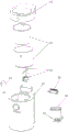
fig. 2 is an exploded view of a kitchen waste disposer according to an embodiment of the present invention;
fig. 3 is a schematic structural diagram of a kitchen waste disposer according to an embodiment of the present invention;
fig. 4 is a schematic structural view of an air duct of the kitchen waste disposer according to an embodiment of the present invention;
FIG. 5 is a schematic structural view of a heating assembly of the kitchen waste disposer according to an embodiment of the present invention;
fig. 6 is a schematic sectional view of a kitchen waste disposer according to an embodiment of the present invention.
In the figure, the position of the upper end of the main shaft,
10. the air purifier comprises a machine body, an air inlet 11, an air inlet fan 12, a cover 13, an air outlet 14, a crushing assembly 15, a purifying assembly 16 and an operation button 17;
20. the device comprises a processing barrel, a 30-air channel, a 31-first connecting part, a 311-extending area, a 312-first protruding part;
40. heating assembly, 41, shell, 411, second connecting part, 412, fastener, 413, second boss, 42, heating body, 421, heat-resistant insulating base body, 422 heating wire.
Detailed Description
The present application will be described in further detail with reference to the following drawings and examples. It is to be understood that the specific embodiments described herein are merely illustrative of the relevant invention and are not limiting of the invention. It should be noted that, for convenience of description, only the portions related to the present invention are shown in the drawings.
It should be noted that the embodiments and features of the embodiments in the present application may be combined with each other without conflict. The present application will be described in detail below with reference to the embodiments with reference to the attached drawings.
The terminology used herein is for the purpose of describing particular embodiments only and is not intended to be limiting of the invention. As used in this specification and the appended claims, the singular forms "a", "an", and "the" are intended to include the plural forms as well, unless the context clearly indicates otherwise. It should also be understood that the term "and/or" as used herein refers to and encompasses any and all possible combinations of one or more of the associated listed items.
As shown in fig. 1 to 6, an embodiment of the present application provides a kitchen waste disposer, including: the machine comprises a machine body 10, wherein a treatment barrel 20 is arranged inside the machine body 10, an air inlet 11 is further formed in the outer wall of the machine body 10, an air duct 30 is arranged inside the machine body 10, at least part of area of the air duct 30 is communicated with the treatment barrel 20 and the air inlet 11, and a heating assembly 40 is arranged in the area, close to the treatment barrel 20, inside the air duct 30;
further comprising: and the connecting assembly is used for fixing the heating assembly 40 on the inner wall of the air duct 30, and a gap is formed between the heating assembly 40 and the inner wall of the air duct 30.
The body 10 may be substantially cylindrical or rectangular. The machine body 10 is provided with an installation cavity for installing the processing barrel 20 therein, wherein the size and shape of the installation cavity are generally adapted to the processing barrel 20, and the shape of the installation cavity may be different from the shape of the processing barrel 20 as long as the processing barrel 20 can be installed in the installation cavity.
The body 10 may be made of various plastics, for example: ABS plastic, PS plastic, PC plastic, PET plastic, or the like; the body 10 may also be made of metal, for example: stainless steel, aluminum alloy, and the like; the embodiment of the present application is not particularly limited in this regard as long as the machine body 10 can be used to mount and carry the processing tub 20, the air duct 30, the heating assembly 40, and the like.
In order to protect the inside of the processing barrel 20, the body 10 is covered with a cover 13, and the cover 13 can be connected with the body 10 by any detachable connection method, such as screw-fitting, riveting, hinging, and the like. When the cover 13 is covered on the machine body 10, it is used to seal the processing barrel 20, which is beneficial to prevent the high temperature gas from spraying out when the garbage disposer is working, avoiding environmental pollution and ensuring the use safety of users.
It is understood that the air inlet 11 is used for the external air to enter the inside of the treating tub 20; the air inlet 11 is formed in a side wall of the machine body 10, which is away from a user when the machine body is normally used, so that air guide is realized, and the attractiveness of the machine body 10 and the use safety of the user are ensured. The air inlet 11 may be, but is not limited to, one, two, or more than two openings, and the shape of the opening is not specifically limited in the embodiment of the present application, for example: circular, square, triangular or circular arc, etc.
The air duct 30 inside the machine body 10 is used for guiding the outside air into the treating tub 20, and the air duct 30 is also used for guiding the air exhausted from the treating tub 20 to the outside, so that the air duct 30 communicates at least partially with the air inlet 11 and the treating tub 20. Wherein, the air duct 30 can extend along the outer wall of the processing barrel 20 to form lateral air intake and lateral air exhaust; the air duct 30 may also extend around the outer wall of the processing barrel 20, as long as the air duct can be used for guiding air, and the embodiment of the present application does not limit the specific arrangement manner of the air duct 30.
Wherein, the heating component 40 inside the air duct 30 heats the air to generate hot air for drying and converting kitchen garbage at high temperature; the heating element 40 may be a heating wire, a heating plate, etc., and the embodiment of the present application is not particularly limited thereto.
In order to avoid that the heating assembly 40 is directly arranged inside the air duct 30 and is in direct contact with the air duct 30 to cause a large amount of heat loss, the heating assembly 40 is fixed on the inner wall of the air duct 30 through the connecting assembly, and a gap is formed between the heating assembly 40 and the inner wall of the air duct 30, so that on one hand, the gap is favorable for heat insulation and prevents heat from being dissipated; on the other hand, the contact area between the heating assembly 40 and the inner wall of the air duct 30 is reduced, so that the heat loss is reduced, and the heat utilization rate is improved.
The connecting assembly can avoid surface contact between the heating assembly 40 and the inner wall of the air duct 30, so that the heat loss of the air duct 30 is reduced; the connecting assembly may comprise any rod-like, bar-like or plate-like structure having a strength to support the heating assembly 40 and a small surface area, and may, of course, further comprise fasteners, such as screws, pins, etc., for further fixing the heating assembly 40.
In actual production and processing, the connecting assembly may be disposed on the air duct 30 or the heating assembly 40, and of course, the connecting assembly may also be disposed on the air duct 30 and the heating assembly 40 at the same time, which is not specifically limited in the embodiment of the present application.
The kitchen waste disposer of the embodiment of the application solves the problems that the contact area of a heating body and an air channel in the existing kitchen waste disposer is large, the heat conductivity of the air channel is good, and the heat loss is large. The coupling assembling of this embodiment has avoided heating element and wind channel inner wall to form the surface contact, reduces the area of contact between heating element and the wind channel inner wall, is favorable to having avoided the large tracts of land contact to cause calorific loss, and then has improved heat utilization efficiency, has prolonged the life of wind channel and organism simultaneously.
As an implementable manner, as shown in fig. 5, the heating assembly 40 includes:
the casing 41, one end of the casing 41 close to the processing barrel 20 in the extending direction of the air duct 30 is provided with an air outlet;
and a heating body 42, wherein the heating body 42 comprises a heat-resistant insulating base 421 arranged inside the housing 41 and a heating wire 422 wound on the heat-resistant insulating base 421.
It is understood that the housing 41 may be configured in a cylindrical or prismatic shape, and any material with good heat resistance and poor heat conductivity may be adopted for the housing 41, which is beneficial to reduce the heat loss of the heating body.
The casing 41 has an air outlet at an end of the air duct 30 extending in a direction close to the processing barrel 20, which is advantageous for guiding hot air generated after heating into the processing barrel.
The heating wire 422 is wound on the heat-resistant insulating base 421, so that short circuit of the heating wire after being electrified can be avoided, and reliable operation can be realized; on the other hand, the heating wire generates heat quickly, the heat dissipation area is increased, and better air heating is facilitated.
The outer shell in the embodiment is favorable for preventing heat generated by the heating body from being directly dissipated to the air duct, so that heat loss is reduced, and meanwhile, the heat-resistant insulating base body ensures that the heating assembly can work safely.
Preferably, the heat-resistant insulating substrate 421 includes a mica sheet. The mica sheet of the embodiment has good heat resistance and insulativity and low cost, and is beneficial to saving the cost.
As an implementation manner, as shown in fig. 4, the connection assembly includes a first connection portion 31 disposed on an inner wall of the air duct 30, the first connection portion 31 includes an extension portion 311 extending from the inner wall of the air duct 30 to an inside of the air duct 30, the extension portion 311 is used for carrying the housing 41, and a gap is formed between an outer wall of the housing 41 and the inner wall of the air duct.
The extension area of the embodiment is beneficial to reliably and stably installing the heating body, reduces the contact area between the heating assembly and the air channel and improves the heat energy utilization rate.
The first connecting portion 31 and the air duct 30 may be integrally formed, or may be formed by secondary processing on the inner wall of the air duct 30; in order to reduce heat dissipation, any material with poor thermal conductivity, such as plastic, may be used for the first connection portion 31.
The extension area of the first connecting portion 31 is used for bearing the housing 41 of the heating assembly 40, and the extension area extends from the inner wall of the air duct 30 to the inside of the air duct, so that a gap is formed between the outer wall of the housing 41 and the inner wall of the air duct 30, contact heat conduction is reduced, and heat loss is reduced.
As a practical matter, at least one first protruding portion 312 is disposed on the extension 311, and the first protruding portion 312 is located at the contact position of the extension and the housing 41.
The first protrusion 312 may be in a shape of an arc, a column, or a bar, which is not limited in this embodiment. The first protrusion 312 is mainly used to avoid surface contact between the housing and the extension region, and further reduce the contact area between the heating assembly and the air duct.
In a specific embodiment, the first connecting portion 31 is a shelf disposed inside the air duct 30, at least one rib is disposed on the shelf, and the housing 41 is mounted on the shelf and fixed by screws, so that the contact area between the housing 41 and the shelf is further reduced due to the rib.
As an implementation manner, as shown in fig. 5 and 6, the connecting assembly further includes a second connecting portion 411 disposed on an outer wall of the housing 41, and the second connecting portion 411 is fixedly connected to the air duct 30 by a fastening member 412. This embodiment has avoided the direct and wind channel contact of shell, and then has reduced heating element's calorific loss.
The second connecting portion 411 and the housing 41 may be integrally formed, or may be formed on the housing 41 by secondary processing, and the second connecting portion 411 may be made of any material with poor thermal conductivity, such as plastic; the second connecting portion 411 may be a link, a lug, or the like provided outside the housing 41, which is not particularly limited in this embodiment.
In a specific embodiment, the second connecting portion 411 may be disposed on an outer side wall of the housing 41, and of course, may be disposed on an end portion of the housing 41 as long as the housing 41 can be fixedly connected to the air duct 30.
It is understood that the second connection portion 411 may be directly connected to the inner wall of the air duct 30, and the second connection portion 411 is connected to the first connection portion 31, so as to install the heating assembly 40 inside the air duct 30.
As an implementable manner, the second connecting portion 411 includes a flange provided at one end of the housing 41, the flange extending from an outer wall surface of the housing 41 toward an inner wall of the air duct 30. This embodiment is favorable to realizing the reliable installation of shell, and simple structure easily processes.
In an implementation manner, the connecting assembly further includes at least one second protrusion 413 disposed on the housing 41, and the second protrusion 413 is located on a side wall of the housing 41 opposite to the inner wall of the air duct 30.
When the number of the second protrusions 413 is two or more, the second protrusions 413 are uniformly arranged on the side wall of the housing 41 at intervals; the second protrusion 413 may have an arc shape, a column shape, or a bar shape, which is not particularly limited in this embodiment. The second protrusion 413 is mainly used to avoid surface contact between the housing 41 and the air duct 30, and further reduce the contact area between the heating assembly and the air duct.
In a specific embodiment, as shown in fig. 5, a plurality of ribs are provided at intervals on the outer sidewall of the housing 41, so as to further reduce the contact area between the housing 41 and the air duct 30.
As an implementation, the air duct 30 is made of plastic. The plastic material in the embodiment is easy to obtain, low in cost, light in weight, beneficial to reduction production and processing, poor in thermal conductivity and capable of reducing heat loss.
In an implementation manner, the air inlet fan 12 is further disposed inside the air duct 30, and the air inlet fan 12 is located at a position of the air duct 30 close to the air inlet 11.
The air intake fan 12 may be various types of blowers or fans, which is not limited in the embodiments of the present application. The air inlet fan 12 increases the air inlet amount, is beneficial to improving the fluidity of hot air in the air duct 30, and improves the treatment efficiency of the kitchen waste disposer.
The kitchen garbage disposer of the present invention will be described in detail below with reference to an example.
As shown in fig. 1-6, a cover 13 is covered on a machine body 10, an air inlet 11 and an air outlet 14 are formed in the outer wall of the machine body 10, a processing barrel 20 is further arranged inside the machine body 10, an air duct 30 is arranged inside the machine body 10, the air duct 30 is communicated with the air inlet 11 and the processing barrel 20, the air duct 30 is also communicated with the processing barrel 20 and the air outlet 14, an air inlet fan 12 is arranged in a region of the air duct 30 close to the air inlet 11, a heating assembly 40 is arranged in a region of the air duct 30 close to the opening of the processing barrel 20, a purification assembly 16 is arranged in the machine body 10 close to the air outlet 14, a crushing assembly 15 is further arranged inside the machine body 10, and a cutter of the crushing assembly 15 is located inside the processing barrel 20;
the inner wall of the air duct 30 is provided with a first connecting portion 31 (rest), the first connecting portion 31 is provided with a first protruding portion 312 (protruding rib), one end of the housing 41 of the heating assembly 40 is provided with an air outlet, the other end is provided with a second connecting portion 411 (flanging), the flanging is lapped on the rest and fixed by a fastener 412 (screw), and the heating assembly 40 is further installed inside the air duct 30.
When the user uses, open lid 13, throw into kitchen garbage inside the garbage disposal bin 20, control operating button 17, the garbage disposer that remains in kitchen begins work, air inlet fan 12 blows in the air inside wind channel 30 with the air, produce hot-air through heating body 42 heating, hot-air is dried to the inside rubbish of garbage disposal bin 20, crushing unit 15 smashes the stirring to rubbish simultaneously, the gaseous entering wind channel 30 that kitchen garbage drying produced is inside, discharge after purifying unit 16 purifies, the treatment effeciency of kitchen garbage has been improved, make the refuse treatment environmental protection clean simultaneously.
In the description of the present application, it is to be understood that the orientation or positional relationship indicated by the directional terms such as "front, rear, upper, lower, left, right", "lateral, vertical, horizontal" and "top, bottom", etc., are generally based on the orientation or positional relationship shown in the drawings, and are used for convenience of description and simplicity of description only, and in the case of not making a reverse description, these directional terms do not indicate and imply that the device or element being referred to must have a particular orientation or be constructed and operated in a particular orientation, and therefore, should not be considered as limiting the scope of the present application; the terms "inner and outer" refer to the inner and outer relative to the profile of the respective component itself.
Spatially relative terms, such as "above … …," "above … …," "above … …," "above," and the like, may be used herein for ease of description to describe one device or feature's spatial relationship to another device or feature as illustrated in the figures. It will be understood that the spatially relative terms are intended to encompass different orientations of the device in use or operation in addition to the orientation depicted in the figures. For example, if a device in the figures is turned over, devices described as "above" or "on" other devices or configurations would then be oriented "below" or "under" the other devices or configurations. Thus, the exemplary term "above … …" can include both an orientation of "above … …" and "below … …". The device may also be oriented 90 degrees or at other orientations and the spatially relative descriptors used herein interpreted accordingly.
It should be noted that the terms "first", "second", and the like are used to define the components, and are only used for convenience of distinguishing the corresponding components, and the terms have no special meanings unless otherwise stated, and therefore, the scope of protection of the present application is not to be construed as being limited.
The above description is only a preferred embodiment of the application and is illustrative of the principles of the technology employed. It will be understood by those skilled in the art that the scope of the present invention is not limited to the specific combination of the above-mentioned features, but also covers other embodiments formed by any combination of the above-mentioned features or their equivalents without departing from the spirit of the present invention. For example, the above features may be replaced with (but not limited to) features having similar functions disclosed in the present application.
Claims (10)
1. Kitchen waste disposer includes: the device comprises a machine body (10), wherein a treatment barrel (20) is arranged in the machine body (10), and an air inlet (11) is formed in the outer wall of the machine body (10), and is characterized in that an air duct (30) is arranged in the machine body (10), at least part of the area of the air duct (30) is communicated with the treatment barrel (20) and the air inlet (11), and a heating assembly (40) is arranged in the area, close to the treatment barrel (20), in the air duct (30);
further comprising: the connecting assembly is used for fixing the heating assembly (40) on the inner wall of the air duct (30), and a gap is formed between the heating assembly (40) and the inner wall of the air duct (30).
2. The kitchen waste disposer of claim 1, wherein the heating assembly (40) comprises:
the shell (41), the shell (41) is provided with an air outlet at one end of the air duct (30) close to the processing barrel (20) in the extending direction;
the heating body (42) comprises a heat-resistant insulating base body (421) arranged inside the shell (41) and a heating wire (422) wound on the heat-resistant insulating base body (421).
3. The kitchen waste disposer of claim 2, wherein the heat resistant insulating matrix (421) comprises mica sheets.
4. The kitchen waste disposer of claim 2, wherein the connection assembly comprises a first connection part (31) disposed on the inner wall of the air duct (30), the first connection part (31) comprises an extension area (311) extending from the inner wall of the air duct (30) to the inside of the air duct (30), the extension area (311) is used for bearing the housing (41), and the gap is formed between the outer wall of the housing (41) and the inner wall of the air duct (30).
5. The kitchen waste disposer of claim 4, characterized in that the extension (311) is provided with at least one first projection (312), the first projection (312) being located at the contact of the extension with the housing (41).
6. The kitchen waste disposer of any of claims 2-5, wherein the connection assembly further comprises a second connection part (411) disposed on an outer wall of the housing (41), the second connection part (411) being fixedly connected to the air duct (30) by a fastener (412).
7. The kitchen waste disposer of claim 6, wherein the second connecting part (411) comprises a flange provided at one end of the housing (41), the flange extending from an outer wall surface of the housing (41) toward an inner wall of the air duct (30).
8. The kitchen waste disposer of any of claims 2-5, wherein the connection assembly further comprises at least one second protrusion (413) disposed on the housing (41), the second protrusion (413) being located on a side wall of the housing (41) opposite to an inner wall of the air duct (30).
9. The kitchen waste disposer of any of claims 1-5, wherein the air duct (30) is made of plastic.
10. The kitchen waste disposer of any of claims 1-5, wherein the air duct (30) is further provided with an air inlet fan (12), and the air inlet fan (12) is located at a position of the air duct (30) close to the air inlet (11).
Priority Applications (1)
| Application Number | Priority Date | Filing Date | Title |
|---|---|---|---|
| CN202120597580.2U CN214950213U (en) | 2021-03-24 | 2021-03-24 | Kitchen garbage processor |
Applications Claiming Priority (1)
| Application Number | Priority Date | Filing Date | Title |
|---|---|---|---|
| CN202120597580.2U CN214950213U (en) | 2021-03-24 | 2021-03-24 | Kitchen garbage processor |
Publications (1)
| Publication Number | Publication Date |
|---|---|
| CN214950213U true CN214950213U (en) | 2021-11-30 |
Family
ID=79038274
Family Applications (1)
| Application Number | Title | Priority Date | Filing Date |
|---|---|---|---|
| CN202120597580.2U Active CN214950213U (en) | 2021-03-24 | 2021-03-24 | Kitchen garbage processor |
Country Status (1)
| Country | Link |
|---|---|
| CN (1) | CN214950213U (en) |
-
2021
- 2021-03-24 CN CN202120597580.2U patent/CN214950213U/en active Active
Similar Documents
| Publication | Publication Date | Title |
|---|---|---|
| CN214950213U (en) | Kitchen garbage processor | |
| CN201731350U (en) | LED lamp bulb with anion generator | |
| CN214314002U (en) | Intelligent heat dissipation structure of low-voltage power distribution cabinet | |
| CN215598039U (en) | Kitchen garbage processor | |
| CN215586763U (en) | Kitchen garbage processor | |
| CN215594265U (en) | Kitchen garbage processor | |
| CN216405608U (en) | Kitchen garbage processor | |
| CN211946843U (en) | Kitchen garbage processor | |
| CN215594264U (en) | Kitchen garbage processor | |
| CN206300233U (en) | Multi-functional integrated range | |
| CN217630283U (en) | Kitchen garbage processor | |
| CN204760814U (en) | Box -style substation | |
| CN102478271A (en) | Range hood | |
| CN215585981U (en) | Deodorization structure and kitchen garbage disposer with same | |
| CN209508668U (en) | A kind of wind guiding systems of appliance system | |
| CN208547022U (en) | A kind of steam self-cleaning type range hood | |
| CN114532855A (en) | Cooking equipment's wind-guiding heat radiation structure and cooking equipment | |
| CN211630510U (en) | Oven for circuit board | |
| GB1602115A (en) | Hot air driers | |
| CN215507114U (en) | Garbage processor | |
| CN214038892U (en) | A panel components and air conditioner for air conditioner | |
| CN211551718U (en) | Bellows structure and domestic appliance | |
| CN111010832A (en) | Heat dissipation air duct structure of electrical control cabinet | |
| CN219248410U (en) | Secondary water supply control cabinet | |
| CN217715022U (en) | Multifunctional integrated biomass particle furnace |
Legal Events
| Date | Code | Title | Description |
|---|---|---|---|
| GR01 | Patent grant | ||
| GR01 | Patent grant |