CN214779962U - Winding device for production of charging stranded wires - Google Patents
Winding device for production of charging stranded wires Download PDFInfo
- Publication number
- CN214779962U CN214779962U CN202121428715.9U CN202121428715U CN214779962U CN 214779962 U CN214779962 U CN 214779962U CN 202121428715 U CN202121428715 U CN 202121428715U CN 214779962 U CN214779962 U CN 214779962U
- Authority
- CN
- China
- Prior art keywords
- winding
- fixedly connected
- bearing
- case
- positive
- Prior art date
- Legal status (The legal status is an assumption and is not a legal conclusion. Google has not performed a legal analysis and makes no representation as to the accuracy of the status listed.)
- Active
Links
Images


Abstract
The utility model discloses a winding device is used in production of stranded conductor that charges, including the winding case, the inside wall fixedly connected with servo motor of winding case, servo motor's output fixedly connected with dwang, the fixed inlaying of left surface of winding case has first bearing, the right-hand member of dwang runs through first bearing and extends to the right side of winding case. This winding device is used in production of stranded conductor that charges, through rotating runner and positive and negative threaded rod, it is close to or keeps away from each other to drive two screw thread section of thick bamboo, through the cooperation with round pin axle and connecting rod, it reciprocates to drive two limiting plates, the inside of card income spacing groove, the realization is spacing fixed to the winding drum, through the cooperation with second electric telescopic handle and layer board, can be convenient hold up the winding drum, and drive the winding drum through first electric telescopic handle and backup pad and carry out the automation and break away from, the staff of being convenient for takes off and installs the winding drum, the rolling efficiency of stranded conductor has effectively been increased.
Description
Technical Field
The utility model belongs to the technical field of the stranded conductor winding is collected, especially, relate to a charging stranded conductor production is with wind.
Background
The stranded wire is realized by rotating a stranded single wire around a stranded wire shaft at a constant angular speed and advancing the stranded wire at a constant speed, the stranded wire is usually made of copper and aluminum, the copper and aluminum wires can be stranded into wire cores of various wire cables with different specifications and sections, and the wire cores are usually applied to cable equipment such as power wires, earphone wires, electronic wires and the like, in the stranded wire production process, the stranded cable is longer and is often required to be wound and collected, the existing cable winding equipment has a simpler structure and is only provided with one wire winding roller, after the collection of the take-up roller is finished, the take-up roller is heavy, workers cannot take down and install the take-up roll quickly and easily, collection of stranded wires by the workers is inconvenient, production efficiency of cables is reduced, therefore, in order to solve the problems, the winding device for producing the charging multi-strand twisted wire is provided.
SUMMERY OF THE UTILITY MODEL
The utility model provides a, it is comparatively simple to aim at solving above-mentioned existing cable winding equipment structure, only is equipped with a receipts line roller, and after receiving the line roller and collecting the completion, it is comparatively heavy to receive the line roller, and the staff can't be light fast takes off and installs receiving the line book, and the staff of being not convenient for has reduced cable production efficiency's problem to the collection work of stranded conductor.
The utility model discloses a realize like this, a winding device is used in production of stranded conductor that charges, including the winding case, the inside wall fixedly connected with servo motor of winding case, servo motor's output fixedly connected with dwang, the fixed first bearing that inlays of left surface of winding case, the right-hand member of dwang runs through first bearing and extends to the right side of winding case, the inside of dwang has been seted up and has been placed the chamber, the inside wall of placing the chamber is fixed respectively and has been inlayed second bearing and third bearing, the inner circle fixedly connected with positive and negative threaded rod of second bearing, the right-hand member of positive and negative threaded rod runs through third bearing and fixedly connected with runner, the surface cover of positive and negative threaded rod is equipped with two screw thread section of thick bamboos, two first standing grooves have all been seted up to the surface of screw thread section of thick bamboo.
The inner wall of the placing cavity is provided with two sliding ports, a limiting plate is arranged inside each sliding port, two second placing grooves are arranged on one side surfaces of the two limiting plates, which are close to each other, each group of the first placing grooves and the second placing grooves are hinged with a connecting rod through two pin shafts, the outer surface of the rotating rod is sleeved with a winding drum, the inner wall of the winding drum is provided with two limiting grooves matched with the limiting plates, a first electric telescopic rod is fixedly embedded on the left side surface of the winding box, a supporting plate is fixedly connected at the right end of the first electric telescopic rod, the upper surface of the supporting plate is fixedly connected with two second electric telescopic rods, the top end of each second electric telescopic rod is fixedly connected with a supporting plate, the outer fixed surface of dwang is connected with the baffle, the baffle is located the left side of receipts reel, the front of winding case is fixed to be inlayed and is had display screen and editing operation dish.
Two first slide openings have been seted up to the right flank of winding case, the bottom surface fixedly connected with L type bracing piece of backup pad, every the left end of L type bracing piece all runs through first slide opening and extends to the inside of winding case.
The right side of winding case is equipped with the movable plate, second slide opening and screw hole have been seted up to the right flank of movable plate, the right flank fixedly connected with slide bar of winding case, the right-hand member of slide bar runs through the second slide opening and extends to the right side of movable plate, the inside wall fixedly connected with protective housing of winding case, the positive and negative motor of inside wall fixedly connected with of protective housing, the output fixedly connected with screw thread post of positive and negative motor, the right flank of winding case is fixed to be inlayed and is had the fourth bearing, the right-hand member of screw thread post runs through fourth bearing and screw hole in proper order and extends to the right side of movable plate, two spacing rings of the fixed surface of screw thread post, the bottom surface fixedly connected with guide ring of movable plate.
The right side face of the winding box is fixedly connected with a rope threading tube, and a measuring length sensor is fixedly embedded in the outer surface of the rope threading tube.
Two guide rollers are fixedly connected to the right side face of the winding box, and the guide rollers are located behind the rope threading barrel.
The front fixedly connected with pilot lamp and control panel of winding case, pilot lamp and control panel all are located the right side of editing operation dish.
Two supporting legs of bottom surface fixedly connected with of winding case, every the equal fixedly connected with mounting panel in bottom of supporting leg, every two mounting holes have all been seted up to the upper surface of mounting panel.
Compared with the prior art, the beneficial effects of the utility model are that: this winding device is used in production of stranded conductor that charges, servo motor through setting up, can utilize servo motor work to drive dwang and a rolling section of thick bamboo and rotate the rolling collection that realizes the stranded conductor, runner through setting up, positive and negative threaded rod, a thread section of thick bamboo, the connecting rod, limiting plate and spacing groove, can rotate runner and positive and negative threaded rod, it is close to or keeps away from each other to drive two thread sections, through the cooperation with round pin axle and connecting rod, drive two limiting plates and reciprocate, the inside of card income spacing groove, realize the spacing fixed to the rolling section of thick bamboo, through the cooperation with second electric telescopic handle and layer board, can be convenient hold up the rolling section of thick bamboo, and drive the rolling section of thick bamboo through first electric telescopic handle and backup pad and carry out the automation and break away from, be convenient for the staff to the taking off and the installation of rolling section of thick bamboo, the rolling efficiency of stranded conductor has effectively been increased.
Drawings
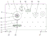
FIG. 1 is a schematic perspective view of the winding box of the present invention;
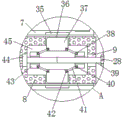
FIG. 2 is a cross-sectional view of the front view of the winding box of the present invention;
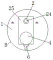
FIG. 3 is a side view of the winding box of the present invention;
FIG. 4 is an enlarged schematic view of the structure at A in FIG. 2 according to the present invention;
fig. 5 is an enlarged schematic view of the structure at B in fig. 3 according to the present invention.
In the figure: 1. a winding box; 2. a second slide hole; 3. a threaded hole; 4. a limiting ring; 5. a threaded post; 6. a guide ring; 7. winding the roll; 8. rotating the rod; 9. three bearings; 10. a control panel; 11. a support plate; 12. a second electric telescopic rod; 13. a support plate; 14. an L-shaped support bar; 15. a first electric telescopic rod; 16. a first slide hole; 17. mounting holes; 18. mounting a plate; 19. supporting legs; 20. editing an operation panel; 21. an indicator light; 22. a display screen; 23. a fourth bearing; 24. a slide bar; 25. moving the plate; 26. a protective shell; 27. a positive and negative motor; 28. a rotating wheel; 29. a baffle plate; 30. a first bearing; 31. a servo motor; 32. a measuring length sensor; 33. a rope threading drum; 34. a guide roller; 35. a limiting groove; 36. a sliding port; 37. a limiting plate; 38. a first placing groove; 39. a positive and negative threaded rod; 40. a pin shaft; 41. a connecting rod; 42. a second placing groove; 43. a threaded barrel; 44. a second bearing; 45. a placement chamber.
Detailed Description
In order to make the objects, technical solutions and advantages of the present invention more clearly understood, the present invention is further described in detail below with reference to the accompanying drawings and embodiments. It should be understood that the specific embodiments described herein are merely illustrative of the invention and are not intended to limit the invention.
In the description of the present invention, it is to be understood that the terms "length", "width", "upper", "lower", "front", "rear", "left", "right", "vertical", "horizontal", "top", "bottom", "inner", "outer", and the like indicate orientations or positional relationships based on those shown in the drawings, and are merely for convenience of description and simplicity of description, and do not indicate or imply that the device or element being referred to must have a particular orientation, be constructed and operated in a particular orientation, and thus, should not be construed as limiting the present invention. In addition, in the description of the present invention, "a plurality" means two or more unless specifically limited otherwise.
Please refer to fig. 1-5, a winding device is used in production of stranded conductor that charges, including winding case 1, the inside wall fixedly connected with servo motor 31 of winding case 1, servo motor 31's output fixedly connected with dwang 8, the left surface of winding case 1 is fixed to be inlayed and is had first bearing 30, the right-hand member of dwang 8 runs through first bearing 30 and extends to the right side of winding case 1, the inside of dwang 8 has been seted up and has been placed chamber 45, the inside wall of placing chamber 45 is fixed respectively to be inlayed and has second bearing 44 and third bearing 9, the inner circle fixedly connected with positive and negative threaded rod 39 of second bearing 44, the right-hand member of positive and negative threaded rod 39 runs through third bearing 9 and fixedly connected with runner 28, the surface cover of positive and negative threaded rod 39 is equipped with two screw thread barrels 43, two first standing grooves 38 have all been seted up to the surface of two screw thread barrels 43.
Place the inner wall of chamber 45 and seted up two slip mouth 36, the inside of every slip mouth 36 all is equipped with limiting plate 37, two second standing grooves 42 have all been seted up to the side that two limiting plates 37 are close to each other, every first standing groove 38 of group and second standing groove 42 all have a connecting rod 41 through two round pin axle 40 joint jointly, the surface cover of dwang 8 is equipped with winding section 7, two spacing grooves 35 with limiting plate 37 looks adaptation are seted up to winding section 7's inner wall, winding box 1's left surface fixed mosaic has first electric telescopic handle 15, first electric telescopic handle 15's right-hand member fixedly connected with backup pad 13, two second electric telescopic handle 12 of last fixed surface connection of backup pad 13, the equal fixedly connected with layer board 11 in top of every second electric telescopic handle 12, the outer surface fixed connection of dwang 8 has baffle 29, baffle 29 is located winding section 7's left side, winding box 1's front fixed mosaic has display screen 22 and editing operation dish 20.
In the utility model, two first sliding holes 16 are arranged on the right side surface of the winding box 1, the bottom surface of the supporting plate 13 is fixedly connected with L-shaped supporting rods 14, the left end of each L-shaped supporting rod 14 penetrates through the first sliding hole 16 and extends to the inside of the winding box 1, the supporting plate 13 can be supported, the stability of the supporting plate 13 during movement is increased, the winding box 7 is convenient to install and disassemble, the right side of the winding box 1 is provided with a movable plate 25, the right side surface of the movable plate 25 is provided with a second sliding hole 2 and a threaded hole 3, the right side surface of the winding box 1 is fixedly connected with a sliding rod 24, the right end of the sliding rod 24 penetrates through the second sliding hole 2 and extends to the right side of the movable plate 25, the inner side wall of the winding box 1 is fixedly connected with a protective shell 26, the inner side wall of the protective shell 26 is fixedly connected with a positive and negative motor 27, the output end of the positive and negative motor 27 is fixedly connected with a threaded column 5, the right side surface of the winding box 1 is fixedly inlaid with a fourth bearing 23, the right-hand member of screw thread post 5 runs through fourth bearing 23 and screw hole 3 in proper order and extends to the right side of movable plate 25, two spacing rings 4 of the fixed surface of screw thread post 5 are connected with, the bottom surface fixedly connected with guide ring 6 of movable plate 25, can utilize positive and negative motor 27 work, it rotates to drive screw thread post 5, through with screw hole 3, the cooperation of slide bar 24 and second slide opening 2, it removes about driving movable plate 25 and guide ring 6, and then drive the horizontal hunting of stranded conductor, be convenient for receive the sequencing of reel 7 to the wire and collect, the right flank fixedly connected with rope threading section of thick bamboo 33 of winding case 1, the fixed surface of rope threading section of thick bamboo 33 inlays and has measured length sensor 32, can carry out length detection to the cable that passes through, through the cooperation with display screen 22, the staff of being convenient for knows the collection length of cable.
Two guide rolls 34 of right flank fixedly connected with of winding case 1, guide roll 34 is located the rear of a rope handling section of thick bamboo 33, can be effectual carry out the wire to the cable stranded conductor, increase the stability that the stranded conductor removed, the positive fixedly connected with pilot lamp 21 and the control panel 10 of winding case 1, pilot lamp 21 and control panel 10 all are located the right side of editing operation dish 20, can make the more convenient control winding case 1 of staff, the collection of the stranded conductor of being convenient for, two supporting legs 19 of bottom surface fixedly connected with of winding case 1, the equal fixedly connected with mounting panel 18 in bottom of every supporting leg 19, two mounting holes 17 have all been seted up to the upper surface of every mounting panel 18, can install winding case 1 fixedly, increase the steadiness of winding case 1, the collection work of the stranded conductor of being convenient for.
The utility model discloses a theory of operation is: when in use, firstly, the twisted stranded wires pass through the two guide rollers 34 and the rope threading cylinder 33, meanwhile, the stranded wires pass through the guide ring 6, the head ends of the stranded wires are clamped in the wire fixing grooves on the surface of the winding cylinder 7, then the servo motor 31 and the positive and negative motor 27 are programmed and controlled by clicking the editing operation panel 20, the servo motor 31 is driven by clicking the control panel 10 to drive the rotating rod 8 and the winding cylinder 7 to rotate, the stranded wires are wound, meanwhile, the positive and negative motor 27 is driven to drive the threaded column 5 to rotate, the moving plate 25 and the guide ring 6 are driven to move left and right through the matching with the threaded hole 3, the sliding rod 24 and the second sliding hole 2, and then the stranded wires are driven to swing left and right, the winding cylinder 7 is convenient to sort and collect the wires, when the winding cylinder 7 needs to be replaced, the rotating wheel 28 and the positive and negative threaded rod 39 are rotated to enable the two threaded cylinders 43 to be close to or far away from each other, and through the matching with the pin shaft 40 and the connecting rod 41, drive two limiting plates 37 and reciprocate, make limiting plate 37 break away from the inside of spacing groove 35, realize tying up the pine of a winding reel 7, through the cooperation with second electric telescopic handle 12 and layer board 11, the convenient holds up winding reel 7 to drive winding reel 7 through first electric telescopic handle 15 and backup pad 13 and break away from automatically, accomplish the quick taking out of winding reel 7, increase staff's work efficiency.
The above description is only exemplary of the present invention and should not be construed as limiting the present invention, and any modifications, equivalents and improvements made within the spirit and principles of the present invention are intended to be included within the scope of the present invention.
Claims (7)
1. The utility model provides a winding device is used in production of stranded conductor charges, includes winding case (1), its characterized in that: the inner side wall of the winding box (1) is fixedly connected with a servo motor (31), the output end of the servo motor (31) is fixedly connected with a rotating rod (8), a first bearing (30) is fixedly embedded on the left side surface of the winding box (1), the right end of the rotating rod (8) penetrates through the first bearing (30) and extends to the right side of the winding box (1), a placing cavity (45) is formed in the rotating rod (8), a second bearing (44) and a third bearing (9) are respectively fixedly embedded in the inner side wall of the placing cavity (45), the inner ring of the second bearing (44) is fixedly connected with a positive and negative threaded rod (39), the right end of the positive and negative threaded rod (39) penetrates through the third bearing (9) and is fixedly connected with a rotating wheel (28), two threaded cylinders (43) are sleeved on the outer surfaces of the positive and negative threaded rods (39), and two first placing grooves (38) are formed in the outer surfaces of the two threaded cylinders (43);
the inner wall of the placing cavity (45) is provided with two sliding ports (36), each sliding port (36) is internally provided with a limiting plate (37), one side face, close to each other, of each limiting plate (37) is provided with two second placing grooves (42), each first placing groove (38) and each second placing groove (42) are jointly hinged to a connecting rod (41) through two pin shafts (40), the outer surface of the rotating rod (8) is sleeved with a winding drum (7), the inner wall of the winding drum (7) is provided with two limiting grooves (35) matched with the limiting plates (37), the left side face of the winding box (1) is fixedly inlaid with a first electric telescopic rod (15), the right end of the first electric telescopic rod (15) is fixedly connected with a supporting plate (13), the upper surface of the supporting plate (13) is fixedly connected with two second electric telescopic rods (12), every the equal fixedly connected with layer board (11) in top of second electric telescopic handle (12), the outer fixed surface of dwang (8) is connected with baffle (29), baffle (29) are located the left side of winding reel (7), the front of winding case (1) is fixed to be inlayed and is had display screen (22) and editing operation dish (20).
2. The winding device for producing a charging stranded wire according to claim 1, characterized in that: two first slide holes (16) have been seted up to the right flank of winding case (1), the bottom surface fixedly connected with L type bracing piece (14) of backup pad (13), every the left end of L type bracing piece (14) all runs through first slide hole (16) and extends to the inside of winding case (1).
3. The winding device for producing a charging stranded wire according to claim 1, characterized in that: the right side of winding case (1) is equipped with movable plate (25), second slide opening (2) and screw hole (3) have been seted up to the right flank of movable plate (25), the right flank fixedly connected with slide bar (24) of winding case (1), the right-hand member of slide bar (24) runs through second slide opening (2) and extends to the right side of movable plate (25), the inside wall fixedly connected with protective housing (26) of winding case (1), the inside wall fixedly connected with positive and negative motor (27) of protective housing (26), the output fixedly connected with screw thread post (5) of positive and negative motor (27), the right flank of winding case (1) is fixed to be inlayed and is had fourth bearing (23), the right-hand member of screw thread post (5) runs through fourth bearing movable plate (23) and screw hole (3) in proper order and extends to the right side of movable plate (25), the external surface fixedly connected with two spacing rings (4) of screw thread post (5), the bottom surface of the moving plate (25) is fixedly connected with a guide ring (6).
4. The winding device for producing a charging stranded wire according to claim 1, characterized in that: the right flank fixedly connected with rope threading section of thick bamboo (33) of winding case (1), the surface mounting of rope threading section of thick bamboo (33) inlays and has measurement length sensor (32).
5. The winding device for producing a charging stranded wire according to claim 1, characterized in that: two guide rollers (34) are fixedly connected to the right side face of the winding box (1), and the guide rollers (34) are located behind the rope penetrating drum (33).
6. The winding device for producing a charging stranded wire according to claim 1, characterized in that: the front face of the winding box (1) is fixedly connected with an indicator lamp (21) and a control panel (10), and the indicator lamp (21) and the control panel (10) are both located on the right side of the editing operation panel (20).
7. The winding device for producing a charging stranded wire according to claim 1, characterized in that: two supporting legs (19) of bottom surface fixedly connected with of winding case (1), every the equal fixedly connected with mounting panel (18) in bottom of supporting leg (19), every two mounting holes (17) have all been seted up to the upper surface of mounting panel (18).
Priority Applications (1)
| Application Number | Priority Date | Filing Date | Title |
|---|---|---|---|
| CN202121428715.9U CN214779962U (en) | 2021-06-25 | 2021-06-25 | Winding device for production of charging stranded wires |
Applications Claiming Priority (1)
| Application Number | Priority Date | Filing Date | Title |
|---|---|---|---|
| CN202121428715.9U CN214779962U (en) | 2021-06-25 | 2021-06-25 | Winding device for production of charging stranded wires |
Publications (1)
| Publication Number | Publication Date |
|---|---|
| CN214779962U true CN214779962U (en) | 2021-11-19 |
Family
ID=78713649
Family Applications (1)
| Application Number | Title | Priority Date | Filing Date |
|---|---|---|---|
| CN202121428715.9U Active CN214779962U (en) | 2021-06-25 | 2021-06-25 | Winding device for production of charging stranded wires |
Country Status (1)
| Country | Link |
|---|---|
| CN (1) | CN214779962U (en) |
Cited By (1)
| Publication number | Priority date | Publication date | Assignee | Title |
|---|---|---|---|---|
| CN116142880A (en) * | 2023-04-18 | 2023-05-23 | 国网山东省电力公司昌邑市供电公司 | Electric power construction conveyer |
-
2021
- 2021-06-25 CN CN202121428715.9U patent/CN214779962U/en active Active
Cited By (2)
| Publication number | Priority date | Publication date | Assignee | Title |
|---|---|---|---|---|
| CN116142880A (en) * | 2023-04-18 | 2023-05-23 | 国网山东省电力公司昌邑市供电公司 | Electric power construction conveyer |
| CN116142880B (en) * | 2023-04-18 | 2023-08-08 | 国网山东省电力公司昌邑市供电公司 | Electric power construction conveyer |
Similar Documents
| Publication | Publication Date | Title |
|---|---|---|
| CN214779962U (en) | Winding device for production of charging stranded wires | |
| CN205170084U (en) | Wire arranging device | |
| CN209442413U (en) | Cable coiling device | |
| CN202917925U (en) | A cable collecting and releasing device used for airplane power supply equipment | |
| CN210339961U (en) | Pay-off rack for construction site of building construction | |
| CN210084661U (en) | Cable coiling mechanism for electric power engineering | |
| CN216471579U (en) | Full-automatic take-up and pay-off device | |
| CN210594717U (en) | Winding drum capable of collecting sizes of various steel cords | |
| CN115632315A (en) | Electrical control cabinet with pipeline and circuit arrangement structure | |
| CN210854737U (en) | Electric wire winder | |
| CN114380139A (en) | Copper-clad steel wire take-up equipment and take-up method | |
| CN214298646U (en) | Cable winding device | |
| CN212366652U (en) | Be applied to draw gear of cable laying | |
| CN209835316U (en) | Clamping mechanism for cable winding and unwinding device | |
| CN204568982U (en) | Gantry is paying out machine initiatively | |
| CN211393337U (en) | Photoelectric composite cable convenient to roll | |
| CN110715281B (en) | Tool and method for conveniently paying off, measuring and installing illumination line | |
| CN210150500U (en) | Take-up device for cable | |
| CN209991989U (en) | Pay-off for engineering survey | |
| CN208326974U (en) | A kind of submerged cable winch gear | |
| CN214652722U (en) | Power cable reel capable of recording length | |
| CN218270743U (en) | Pay-off is used in engineering survey and drawing | |
| CN218482596U (en) | Cable laying device for network engineering | |
| CN217867200U (en) | Plastic film coiling mechanism for digital printing | |
| CN211619664U (en) | Electric power cable collecting device |
Legal Events
| Date | Code | Title | Description |
|---|---|---|---|
| GR01 | Patent grant | ||
| GR01 | Patent grant |