CN214770248U - Automatic device for assembling Y-type remaining needle steel needle, anti-overflow plug and needle handle - Google Patents
Automatic device for assembling Y-type remaining needle steel needle, anti-overflow plug and needle handle Download PDFInfo
- Publication number
- CN214770248U CN214770248U CN202120456523.2U CN202120456523U CN214770248U CN 214770248 U CN214770248 U CN 214770248U CN 202120456523 U CN202120456523 U CN 202120456523U CN 214770248 U CN214770248 U CN 214770248U
- Authority
- CN
- China
- Prior art keywords
- needle
- cylinder
- overflow plug
- steel needle
- plug
- Prior art date
- Legal status (The legal status is an assumption and is not a legal conclusion. Google has not performed a legal analysis and makes no representation as to the accuracy of the status listed.)
- Active
Links
Images


Abstract
The utility model relates to the technical field of medical equipment, in particular to an automatic device for assembling a Y-type remaining needle steel needle with an anti-overflow plug and a needle handle, which comprises a machine table, wherein the table top is sequentially provided with a steel needle automatic feeding station, a steel needle positioning station, a steel needle detection station, an anti-overflow plug assembling station, an anti-overflow plug dedusting station, an anti-overflow plug positioning station, a steel needle flat clamping station, a needle handle assembling station, a needle handle angle adjusting station, a qualified product blanking station and a defective product blanking station; in addition, an index plate is arranged right above the machine table and fixedly connected with the machine table through a connecting shaft; still including the delivery carousel, the delivery carousel is located on the connecting axle between board and the graduated disk, realize through mechanical promotion the delivery carousel is followed the connecting axle operation, wherein, the delivery carousel outside still is equipped with the tucking tool that carries out processing with the steel needle transmission to each station, realizes the assembly unified and full automatization, and very big improvement production efficiency.
Description
Technical Field
The utility model relates to an automatic assembly field, in particular to Y formula is kept somewhere automation equipment of needle steel needle and anti-overflow stopper, needle handle equipment.
Background
In industrial production, most production processes of the Y-type indwelling needle are completed by workers with the assistance of some simple tools, the degree of full automation is low, the degree of dependence on the workers is high, and human factors have great influence on the quality of products; in addition, for some disclosed automation equipment, the whole structure is single, detailed structural function description is omitted, no detection device is used for carrying out corresponding inspection quality inspection on products, and the production efficiency and the yield are low.
SUMMERY OF THE UTILITY MODEL
Based on this, the utility model aims at providing a Y formula is kept somewhere needle steel needle and is prevented spilling over automation equipment of stopper, needle handle equipment to prior art's not enough.
In order to achieve the above purpose, the utility model adopts the following technical scheme:
the automatic equipment for assembling the Y-type remaining needle steel needle, the anti-overflow plug and the needle handle comprises a machine table, wherein a steel needle automatic feeding station, a steel needle positioning station, a steel needle detection station, an anti-overflow plug assembling station, an anti-overflow plug dedusting station, an anti-overflow plug positioning station, a steel needle flattening station, a needle handle assembling station, a needle handle angle adjusting station, a qualified product blanking station and a defective product blanking station are sequentially arranged on the table surface of the machine table in an annular mode; in addition, an index plate is arranged right above the machine table and used for bearing the auxiliary device of the station, and the machine table and the index plate are fixedly connected through a connecting shaft; still including the delivery carousel, the delivery carousel is located on the connecting axle between board and the graduated disk, realize through mechanical pushing the delivery carousel is followed the connecting axle operation, wherein, the delivery carousel outside still is equipped with the tucking tool that carries out processing with the steel needle transmission to each station.
As a further improvement, the tucking tool comprises an upper body and a lower body, the upper body and the lower body are connected through a spring in a movable mode, the upper body is provided with a pressing part, the lower body is provided with a top block, a steel needle can be arranged between the upper body and the top block, the pressing part is pressed to realize that the steel needle is fixed without pressing, and the steel needle is in sliding fit with the tucking tool.
As a further improvement of the utility model, the steel needle automatic feeding station comprises an ejection lifting cylinder and a material receiving lifting cylinder which are fixedly arranged on the machine platform, wherein an ejection rod is arranged at the top of the ejection lifting cylinder, and the steel needle is ejected out of a material bin arranged above the ejection rod through the ejection rod and is transmitted to a material receiving jig arranged at the upper part of the material receiving lifting cylinder; one end of the receiving jig, which is close to the ejector rod, is provided with a needle lifting block for placing a steel needle; the needle lifting block is two protruding blocks arranged outside the material receiving jig and used for placing the front end and the rear end of the steel needle, and a space capable of containing an ejector rod is reserved between the two protruding blocks; a material receiving transverse moving cylinder is arranged between the material receiving lifting cylinder and the material receiving smelting tool; the material receiving transverse moving cylinder drives the needle lifting block on the material receiving jig to transversely move to the position of the material ejecting rod;
still press from both sides the device including getting, press from both sides the device and include steel needle clamping jaw cylinder, horizontal migration cylinder and horizontal migration cylinder mounting, steel needle clamping jaw cylinder one end is connected with the steel needle clamping jaw, and the other end passes through the connecting piece and links to each other with the horizontal migration cylinder, the horizontal migration cylinder sets firmly on the graduated disk through horizontal migration cylinder mounting, steel needle clamping jaw cylinder drive the steel needle clamping jaw will lift the steel needle on the needle piece and press from both sides and get the action, the operation of horizontal migration cylinder will the steel needle that the steel needle clamping jaw was pressed from both sides and is got shifts to in the pressing needle smelting tool.
As a further improvement of the present invention, the steel needle positioning station includes a thimble cylinder and a thimble cylinder fixing member, and the thimble cylinder is fixedly arranged on the machine table through the thimble cylinder fixing member; the thimble cylinder is provided with a thimble head which pushes the steel needle in the needle pressing jig to a certain position.
As the utility model discloses a further improvement, the steel needle detects the station and includes that the steel needle detects sensor, sensor mount, the steel needle detects the sensor and sets firmly on the board through the sensor mount, the steel needle detects the sensor and is used for detecting have or not the steel needle in the tucking smelting tool.
As a further improvement of the present invention, the anti-overflow plug assembly station comprises an anti-overflow plug feeding device, an anti-overflow plug dipping alcohol, a tapping device and a steel needle clamping device, the anti-overflow plug feeding device comprises an anti-overflow plug vibrating disc, the anti-overflow plug vibrating disc conveys the anti-overflow plug to the anti-overflow plug dipping alcohol and the tapping device by direct vibration of the anti-overflow plug, the anti-overflow plug dipping alcohol and the tapping device comprises a first anti-overflow plug lifting cylinder, a second anti-overflow plug lifting cylinder and an anti-overflow plug assembly translation cylinder, the first anti-overflow plug lifting cylinder is slidably connected with the first anti-overflow plug translation cylinder, and the first anti-overflow plug translation cylinder and the second anti-overflow plug lifting cylinder are installed on the anti-overflow plug assembly translation cylinder together; the bottoms of the first anti-overflow plug lifting cylinder and the second anti-overflow plug lifting cylinder are respectively provided with a first anti-overflow plug clamping jaw and a second anti-overflow plug clamping jaw;
the anti-overflow plug dipping alcohol and tapping device further comprises an alcohol groove arranged corresponding to the first anti-overflow plug lifting cylinder and an anti-overflow plug tapping blade arranged corresponding to the second anti-overflow plug lifting cylinder, the tip end of the blade is provided with a tapping groove opposite to the position, the first anti-overflow plug lifting cylinder operates to clamp the anti-overflow plug conveyed on the vibration disc through the first anti-overflow plug clamping jaw, the anti-overflow plug is transferred to the alcohol groove to be dipped through the first anti-overflow plug translation cylinder, and the anti-overflow plug dipped in alcohol is transferred to the tapping groove through the anti-overflow plug assembling translation cylinder; the blade is fixed on the blade clamp, an anti-overflow plug hole opening cylinder is arranged at the bottom of the blade clamp, and the anti-overflow plug hole opening cylinder operates to drive the blade to move forwards to open a hole in the anti-overflow plug; a second anti-overflow plug clamping jaw arranged on the second anti-overflow plug lifting cylinder clamps the anti-overflow plug after the hole is opened, and the anti-overflow plug is transferred to an anti-overflow plug to-be-assembled clamp by the anti-overflow plug assembling translation cylinder; the bottom of the anti-overflow plug to-be-assembled clamp is connected with an anti-overflow plug to-be-assembled clamp propelling electric cylinder through a fixing piece, and the anti-overflow plug to-be-assembled clamp propelling electric cylinder drives the anti-overflow plug to-be-assembled clamp to move and assemble an anti-overflow plug onto a steel needle;
the steel needle clamping device comprises an upper clamping position and a lower clamping position, wherein the upper clamping position is fixedly arranged on the dividing plate, the lower clamping position is fixedly arranged on the machine table, the upper clamping position and the lower clamping position respectively comprise an upper clamping position cylinder and a lower clamping position cylinder, and clamping rods are respectively arranged at the bottom of the upper clamping position cylinder and on the upper portion of the lower clamping position cylinder.
As a further improvement of the utility model, the anti-overflow plug dust removal station comprises a blowhead advancing cylinder, a blowhead fixing block is arranged on one side of the blowhead advancing cylinder close to the needle pressing jig, a blowing cavity for accommodating the steel needle and the anti-overflow plug is arranged on the blowhead fixing block body, and an air pressure source is connected inside the blowing cavity; the air blowing head advancing cylinder operates to drive the air blowing head fixing block to move forwards and carry out dust blowing treatment on a steel needle and an anti-overflow plug which are arranged in the needle pressing jig; the blowing head forward cylinder fixing frame is fixedly arranged at the bottom of the blowing head forward cylinder and is fixed on the machine table,
as a further improvement of the present invention, the anti-overflow plug positioning station includes an anti-overflow plug push block and a push block advancing cylinder, the anti-overflow plug push block is fixedly arranged on one side of the push block advancing cylinder close to the needle pressing jig, the push block advancing cylinder operates to drive the anti-overflow plug push block to move forward and push the anti-overflow plug on the steel needle to a certain position, and the push block advancing cylinder is fixed on the machine table through a push block advancing cylinder bracket;
still include the smelting tool and push down the device, the smelting tool pushes down the device and includes that the smelting tool pushes down positioning cylinder, smelting tool push down the mounting, the smelting tool pushes down positioning cylinder and passes through the smelting tool pushes down the mounting and fixes on the graduated disk, the smelting tool pushes down positioning cylinder bottom and installs the press head that can contact tucking tool smelting tool and press the splenium.
As a further improvement of the utility model, the steel needle flat clamping station comprises a flat clamping workpiece and a steel needle flat clamping cylinder, the steel needle flat clamping cylinder drives the flat clamping workpiece to act to clamp the steel needle flat, the steel needle flat clamping cylinder is fixed on a steel needle flat clamping cylinder fixing part, and the steel needle flat clamping cylinder fixing part is fixed on the machine table; also comprises a jig pressing device fixedly arranged on the index plate.
As a further improvement of the present invention, the needle handle assembly station includes a needle handle feeding device, a needle handle pushing device and a steel needle clamping device, the needle handle feeding device includes a needle handle material vibrating tray and a needle handle direct vibration, the needle handle material vibrating tray conveys the needle handle to the needle handle pushing device through the needle handle direct vibration, and the needle handle pushing device is provided with a needle handle positioning groove for adjusting the angle and position of the needle handle; the needle handle clamping jaw air cylinder is provided with a needle handle clamping jaw for clamping the tail part of the needle handle, and the back part of the needle handle clamping jaw air cylinder is provided with a needle handle transferring motor set for transferring and assembling the needle handle clamped by the needle handle clamping jaw to a steel needle; also comprises a steel needle clamping device. As a further improvement of the present invention, the needle handle angle adjustment station includes a needle handle angle adjustment cylinder, one end of the needle handle angle adjustment cylinder near the needle pressing jig is provided with a needle handle limiting claw, the other end is fixedly connected with a needle handle angle adjustment cylinder mounting, the bottom end of the needle handle angle adjustment cylinder mounting is provided with a needle handle angle adjustment advancing cylinder, and the needle handle angle adjustment advancing cylinder is fixedly mounted on the machine table;
needle handle angle adjusting device still is equipped with needle handle detection sensor, needle handle detection sensor installs directly over the steel needle position, and needle handle detection sensor one end is fixed in body position on the tucking smelting tool.
As a further improvement of the utility model, the defective product blanking station comprises a blanking clamping jaw and a blanking forward moving cylinder, one end of the blanking clamping jaw is connected with a blanking clamping jaw cylinder for driving the blanking clamping jaw to clamp and open, the blanking clamping jaw cylinder is connected with the blanking forward moving cylinder in the vertical direction through a fixing part, and the blanking forward moving cylinder is installed on the dividing plate through a blanking forward moving cylinder fixing part;
still including locating under the unloading clamping jaw and be used for collecting the waste product box of defective products, the waste product box sets firmly on the board.
The utility model has the advantages that:
1. the complete Y-type remaining needle steel needle, anti-overflow plug and needle handle assembly production equipment is provided, uniform assembly and full automation are realized, and the production efficiency is greatly improved;
2. qualified products and defective products can be distinguished through the detection of the needle handle, so that the products are reasonable in quality distribution;
3. through the arrangement of the automatic steel needle feeding device, the automatic overflow-preventing plug feeding device and the automatic needle handle feeding device, the feeding is uniform and more intelligent; the anti-overflow plug dust removal device is also arranged, so that the anti-overflow plug is prevented from being polluted;
4. the anti-overflow stopper assembling device is provided with an anti-overflow stopper dipping alcohol process, so that the anti-overflow stopper can be conveniently perforated.
Drawings
In order to more clearly illustrate the embodiments of the present invention or the technical solutions in the prior art, the drawings used in the description of the embodiments or the prior art will be briefly described below, it is obvious that the drawings in the following description are only some embodiments of the present invention, and for those skilled in the art, other drawings can be obtained according to these drawings without creative efforts.
Fig. 1 is a schematic view of the overall assembly structure of the present invention.
Figure 2 is the utility model discloses steel needle automatic feeding station structure sketch map.
Figure 3 is the utility model discloses steel needle location station structure sketch map.
Figure 4 is the utility model discloses steel needle detects station structure sketch map.
Fig. 5 is a schematic view of the structure of the assembly station of the anti-overflow plug of the present invention.
Figure 6 is the utility model discloses anti-overflow stopper dust removal station structure sketch map.
Figure 7 is the utility model discloses anti-overflow stopper location station structure sketch map.
FIG. 8 is a schematic view of the structure of the steel needle clamping station of the present invention.
Fig. 9 is the structure schematic diagram of the needle handle assembling station of the utility model.
Fig. 10 is a schematic view of the needle handle angle adjusting station structure of the present invention.
Figure 11 is the utility model discloses qualified product unloading station structure sketch map.
Fig. 12 is the utility model discloses defective products unloading station structure sketch map.
Figure 13 is the utility model discloses connect material smelting tool position structure schematic diagram in steel needle automatic feeding station.
Fig. 14 is the structural schematic diagram of the ejector beam position in the automatic steel needle feeding station of the utility model.
Fig. 15 is the enlarged view of the indicating area a in the anti-overflow plug assembling station shown in fig. 5.
FIG. 16 is a schematic structural view of a blowing head fixing block in the anti-overflow plug dust removal station of the utility model.
Fig. 17 is a side view of the needle handle assembly station of the present invention.
Fig. 18 is a schematic view of the structure of the needle pressing jig of the present invention.
Fig. 19 is a schematic view of a part of the needle pressing jig of the present invention.
Fig. 20 is a schematic structural view of the steel needle clamping device of the present invention.
Fig. 21 is the structure diagram of the utility model of a tool pressing device.
Fig. 22 is a schematic structural diagram of the product of the present invention.
In the figure: a feeding station 1, a steel needle positioning station 2, a steel needle detection station 3, an anti-overflow plug assembling station 4, an anti-overflow plug dedusting station 5, an anti-overflow plug positioning station 6, a steel needle flattening station 7, a needle handle assembling station 8, a needle handle angle adjusting station 9, a qualified product blanking station 10, a defective product blanking station 11, a machine table 12, a carrying rotary table 13, a dividing disc 14, a steel needle 15, an anti-overflow plug 16, a needle handle 17, a needle pressing smelting tool 100, an upper body 1004, a lower body 1005, a spring 1001, a pressing part 1002, a top block 1003, an upper clamping position cylinder 2001, a lower clamping position cylinder 2002, a clamping rod 2003, a smelting tool pressing positioning cylinder 3001, a smelting tool pressing fixing part 3002, a pressing head 3003, a top material lifting cylinder 111, a top material rod 115, a steel needle clamping jaw cylinder 121, a horizontal moving cylinder 122, a horizontal moving cylinder 123, a steel needle clamping jaw 124, a storage bin 131, a storage bin 132 and a receiving smelting tool 134, a material receiving transverse moving cylinder 136, a material receiving lifting cylinder 138, a needle lifting block 1341, a needle cylinder 21, a needle cylinder fixing member 22, a needle head 23, a steel needle detection sensor 31, a sensor fixing frame 32, an anti-overflow plug material vibrating disc 40, a first anti-overflow plug lifting cylinder 411, a second anti-overflow plug lifting cylinder 412, a first anti-overflow plug translation cylinder 413, an anti-overflow plug assembling translation cylinder 414, a first anti-overflow plug clamping jaw 415, a second anti-overflow plug clamping jaw 416, an alcohol tank 421, a blade 422, a blade clamp 423, an anti-overflow plug hole opening cylinder 424, an anti-overflow plug assembling clamp 425, an anti-overflow plug assembling clamp propelling electric cylinder 426, an anti-overflow plug distributing cylinder 427, a first clamping jaw 401, a second clamping jaw 402, a dust removal box 51, a blowing head fixing block 53, a blowing head advancing cylinder 54, a blowing head advancing cylinder fixing frame 55, a blowing chamber 531, an anti-overflow plug pushing block 61, a pushing block protruding part 62, a pushing block advancing cylinder 63, the automatic feeding device comprises a push block advancing cylinder support 64, a flat clamping workpiece 71, a steel needle flat clamping cylinder 72, a steel needle flat clamping cylinder fixing piece 73, a needle shank material vibration disc 80, a needle shank direct vibration 801, a needle shank transfer motor set 811, a needle shank clamping jaw cylinder 812, a needle shank positioning groove 813, a needle shank distribution cylinder 814, a needle shank clamping jaw 815, a material blocking block 816, a needle shank angle adjusting cylinder 91, a needle shank limiting jaw 92, a needle shank angle adjusting cylinder fixing piece 93, a needle shank angle adjusting advancing cylinder 94, a needle shank detection sensor 95, a manipulator 101, a manipulator clamping jaw cylinder 102, a blanking clamping jaw 1101, a blanking clamping jaw cylinder 1102, a blanking advancing cylinder 1103, a blanking advancing cylinder fixing piece 1104 and a waste box 1105.
Detailed Description
The technical solution in the embodiments of the present invention will be clearly and completely described below with reference to the accompanying drawings. It is to be understood that the embodiments described are only some embodiments of the invention, and not all embodiments. Based on the embodiments in the present invention, all other embodiments obtained by a person skilled in the art without creative work belong to the protection scope of the present invention.
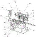
As shown in fig. 1-22, an automatic device for assembling a Y-type remaining needle steel needle, an anti-overflow plug and a needle handle comprises a machine table 12, and is characterized in that a steel needle automatic feeding station 1, a steel needle positioning station 2, a steel needle detection station 3, an anti-overflow plug assembling station 4, an anti-overflow plug dust removal station 5, an anti-overflow plug positioning station 6, a steel needle flattening station 7, a needle handle assembling station 8, a needle handle angle adjusting station 9, a qualified product blanking station 10 and a defective product blanking station 11 are annularly and sequentially arranged on a table top of the machine table 12; in addition, an index plate 14 is arranged right above the machine table 12, the index plate 14 is used for bearing an auxiliary device of the station, and the machine table 12 and the index plate 14 are fixedly connected through a connecting shaft; still include carrying carousel 13, carrying carousel 13 locates on the connecting axle between board 12 and the graduated disk 14, realize through mechanical pushing carrying carousel 13 is followed the connecting axle operation, wherein, carrying carousel 14 outside still is equipped with and transmits the steel needle to each station and carries out the tucking jig 100 that processes.
In a specific embodiment, further, the needle pressing jig 100 includes an upper body 1004 and a lower body 1005, the upper body 1004 and the lower body 1005 are movably connected through a spring 1001, the upper body 1004 is provided with a pressing portion 1002, the lower body 1005 is provided with a top block 1003, the steel needle 15 can be placed between the upper body 1004 and the top block 1003, the pressing portion 1002 is pressed to fix the steel needle 15, and when the pressing is not performed, the steel needle 15 is in sliding fit with the needle pressing jig 100.
In a specific embodiment, further, the steel needle automatic feeding station 1 includes an ejecting lifting cylinder 111 and a receiving lifting cylinder 138 fixedly arranged on the machine 12, an ejecting rod 115 is arranged at the top of the ejecting lifting cylinder 111, the steel needle 15 is ejected from a bin 131 arranged above the ejecting rod 115 through the ejecting rod 115, and is transferred to a receiving jig 134 arranged at the upper part of the receiving lifting cylinder 138; the steel needle ejection device further comprises a bin fixing frame 132 for fixing the bin 131, preferably, the bin 131 is hollow, so that the ejector rod 115 can smoothly penetrate through the middle of the bin 131 and eject the steel needle 15, and the purpose of ejecting one steel needle 15 at a time is achieved; as shown in fig. 14, the upper part of the ejector rod 115 is further provided with an ejector groove 1151 matched with the cross section of the steel needle 15, and the ejector groove 1151 can only accommodate one steel needle 15 at a time.
As shown in fig. 13, in detail, one end of the receiving jig 134 near the ejector bar 115 is provided with a needle lifting block 1341 for placing a steel needle 15; the needle lifting block 1341 is two protruding blocks arranged outside the receiving jig 134, and a steel needle 15 accommodating groove is arranged at a corresponding position of the protruding blocks and used for accommodating the front end and the rear end of the steel needle 15, and a space for accommodating the ejector rod 115 is reserved between the two protruding blocks; in addition, a material receiving transverse moving cylinder 136 is arranged between the material receiving lifting cylinder 138 and the material receiving jig 134; the material receiving transverse moving cylinder 136 drives the material receiving jig 134 to lift the needle block 1341 to move transversely to the position of the material ejecting rod 115.
The clamping device comprises a steel needle clamping jaw cylinder 121, a horizontal moving cylinder 122 and a horizontal moving cylinder fixing piece 123, one end of the steel needle clamping jaw cylinder 124 is connected with a steel needle clamping jaw 124, the other end of the steel needle clamping jaw cylinder is connected with the horizontal moving cylinder 122 through a connecting piece, and the horizontal moving cylinder 122 is fixedly arranged on the dividing plate 14 through the horizontal moving cylinder fixing piece 123. The steel needle clamping jaw cylinder 121 drives the steel needle clamping jaw 124 to clamp the steel needle 15 on the needle lifting block 1341, and the horizontal moving cylinder 122 operates to transfer the steel needle 15 clamped by the steel needle clamping jaw 124 to the needle pressing jig 100.
Preferably, in order to improve the production efficiency, the automatic steel needle feeding device 1 can be repeatedly arranged to perform double-station feeding.
In a specific embodiment, further, the steel needle positioning station 2 includes an ejector pin cylinder 21 and an ejector pin cylinder fixing member 22, and the ejector pin cylinder 21 is fixed on the machine 12 through the ejector pin cylinder fixing member 22; the thimble cylinder 21 is provided with a thimble head 23 for pushing the steel needle 15 in the needle pressing jig 100 to a certain position.
In a specific embodiment, further, the steel needle detection station 3 includes a steel needle detection sensor 31 and a sensor fixing frame 32, the steel needle detection sensor 31 is fixedly arranged on the machine 12 through the sensor fixing frame 32, and the steel needle detection sensor 31 is used for detecting whether a steel needle is present in the needle pressing jig 100; the steel needle detection sensor 31 is a photoelectric sensor, and detects the presence or absence of the steel needle 15 by using the light reflection principle.
In a specific embodiment, further, the overflow-preventing plug assembling station 4 comprises an overflow-preventing plug feeding device, an overflow-preventing plug dipping alcohol, a hole forming device and a steel needle clamping device, the overflow-preventing plug feeding device comprises an overflow-preventing plug vibrating disc 40, the overflow-preventing plug vibrating disc 40 conveys the overflow-preventing plug 16 to the overflow-preventing plug dipping alcohol and the hole forming device through overflow-preventing plug direct vibration, the overflow-preventing plug dipping alcohol and hole forming device comprises a first overflow-preventing plug lifting cylinder 411, a second overflow-preventing plug lifting cylinder 412 and an overflow-preventing plug assembling translation cylinder 414, the first overflow-preventing plug lifting cylinder 411 is slidably connected with a first overflow-preventing plug translation cylinder 413, and the first overflow-preventing plug translation cylinder 413 and the second overflow-preventing plug lifting cylinder 412 are mounted on the overflow-preventing plug assembling translation cylinder 414 together; the bottoms of the first anti-overflow plug lifting cylinder 411 and the second anti-overflow plug lifting cylinder 412 are respectively provided with a first anti-overflow plug clamping jaw 415 and a second anti-overflow plug clamping jaw 416.
The anti-overflow plug dipping alcohol and tapping device further comprises an alcohol groove 421 corresponding to the first anti-overflow plug lifting cylinder 411 and an anti-overflow plug tapping blade 422 corresponding to the second anti-overflow plug lifting cylinder 412, a tapping groove 428 is arranged at the position opposite to the tip end of the blade 422, the first anti-overflow plug lifting cylinder 411 is operated to clamp the anti-overflow plug 16 conveyed on the vibrating disc through the first anti-overflow plug clamping jaw 415, the anti-overflow plug 16 is transferred to the alcohol groove 421 for dipping through the first anti-overflow plug translation cylinder 413, and the anti-overflow plug 16 dipped in alcohol is transferred to the tapping groove 428 through the anti-overflow plug assembling translation cylinder 414; the blade 422 is fixed on the blade clamp 423, the anti-overflow plug hole-forming cylinder 424 is arranged at the bottom of the blade clamp 423, and the anti-overflow plug hole-forming cylinder 424 operates to drive the blade 422 to move forwards to form holes on the anti-overflow plug 16 in the hole-forming groove 428; a second anti-overflow plug clamping jaw 416 arranged on the second anti-overflow plug lifting cylinder 412 clamps the anti-overflow plug 16 after the opening is formed, and transfers the anti-overflow plug to-be-assembled clamp 425 through the anti-overflow plug assembling translation cylinder 414; the bottom of the anti-overflow plug to-be-assembled clamp 425 is connected with an anti-overflow plug to-be-assembled clamp propelling electric cylinder 426 through a fixing piece, and the anti-overflow plug to-be-assembled clamp propelling electric cylinder 426 drives the anti-overflow plug to-be-assembled clamp 425 to move and assemble the anti-overflow plug 16 onto the steel needle 15; in detail, the anti-overflow plug to be assembled clamp 425 has a limiting effect on the anti-overflow plug 16, when the anti-overflow plug to be assembled clamp pushes the electric cylinder 426 to drive the anti-overflow plug 16 to be close to the steel needle 15 for assembly, the anti-overflow plug to be assembled clamp 425 reversely supports the anti-overflow plug 16 to prevent the anti-overflow plug from slipping, and the anti-overflow plug to be assembled clamp 425 leaves a steel needle 15 channel.
In detail, the anti-overflow plug 16 dipped in alcohol increases a certain degree of lubrication, which facilitates the tapping operation.
As shown in fig. 15, the anti-spill plug clamping jaws are preferably arranged in arc-shaped notches, and the notches are sized to be capable of kneading the anti-spill plug 16, so that the anti-spill plug 16 is buckled in the arc-shaped notches by the elasticity of the anti-spill plug 16 and is fixed.
In more detail, the position of the opening groove 428 and the position of the anti-overflow plug to-be-assembled clamp 425 are respectively provided with a first clamping jaw 401 and a second clamping jaw 402, and the first clamping jaw 401 and the second clamping jaw 402 are respectively connected with a clamping jaw air cylinder for driving the clamping jaws to open and close, so that the anti-overflow plugs on the first anti-overflow plug clamping jaw 415 and the second anti-overflow plug clamping jaw 416 are clamped and placed in the opening groove 428 and the anti-overflow plug to-be-assembled clamp 425.
As shown in fig. 20, the steel needle clamping device includes an upper clamping position fixed on the index plate 14 and a lower clamping position fixed on the machine table 12, the upper clamping position and the lower clamping position respectively include an upper clamping position cylinder 2001 and a lower clamping position cylinder 2002, and clamping rods 2003 are respectively disposed at the bottom of the upper clamping position cylinder 2001 and at the upper portion of the lower clamping position cylinder 2002. In detail, the upper clamping position cylinder 2001 and the lower clamping position cylinder 2002 work together to drive the two clamping rods 2003 to approach and clamp the steel needle 15, so that good fixing and protecting effects are achieved, and the phenomenon that the steel needle 15 slides or twists in the process of assembling the anti-overflow plug 16 is prevented.
Preferably, in order to improve the production efficiency, the anti-overflow plug assembling station 4 can be repeatedly arranged to perform double-station feeding.
The specific work flow of the station is as follows: the anti-overflow plug material vibrating disc 40 conveys the anti-overflow plug 16 to a feeding position of an anti-overflow plug alcohol dipping and tapping device through anti-overflow plug direct vibration, an anti-overflow plug material distributing cylinder 427 is arranged at the feeding position and is used for ejecting one anti-overflow plug 16 once, then, the first anti-overflow plug lifting cylinder 411 pushes the first anti-overflow plug clamping jaw 415 to descend and clamp the anti-overflow plug 16, the anti-overflow plug 16 is returned to the initial position, the first anti-overflow plug translation cylinder 413 operates to transfer the anti-overflow plug 16 to a corresponding position above the alcohol tank 421, and the first anti-overflow plug lifting cylinder 411 pushes the first anti-overflow plug clamping jaw 415 to the interior of the alcohol tank 421 again, so that the anti-overflow plug 16 picks up alcohol; after alcohol dipping, the first anti-overflow plug clamping jaw 415 retracts, the anti-overflow plug assembly translation cylinder 414 drives the first anti-overflow plug translation cylinder 413 to displace, the anti-overflow plug 16 is transferred to the position right above the opening groove 428, then the first anti-overflow plug lifting cylinder 411 pushes out the first anti-overflow plug clamping jaw 415 again and puts the anti-overflow plug 16 in the opening groove 428, at the moment, the anti-overflow plug opening cylinder 424 pushes the blade 422 fixedly mounted on the blade clamp 423 to move forwards, and the anti-overflow plug 16 is subjected to opening operation. Then, the anti-spill plug assembling translation cylinder 414 drives the second anti-spill plug lifting cylinder 412 to displace to a corresponding position above the opening groove 428, the second anti-spill plug lifting cylinder 412 pushes out the second anti-spill plug clamping jaw 416 to clamp the anti-spill plug 16 after opening, and the anti-spill plug 16 is transferred into the anti-spill plug assembling jig 425 under the cooperation of the anti-spill plug assembling translation cylinder 414. Thereafter, the anti-spill plug assembling jig pushing electric cylinder 426 pushes the anti-spill plug assembling jig 425 to assemble the anti-spill plug 16 to the steel needle 15.
It should be noted that:
(1) during the process of tapping the anti-spill plug 16, the first anti-spill plug translation cylinder 413 and the first anti-spill plug lifting cylinder 411 have recovered the initial positions and perform a machining action on the next anti-spill plug 16;
(2) the moving track of the first anti-overflow plug translation cylinder 413 on the anti-overflow plug assembly translation cylinder 414 and the moving track of the second anti-overflow plug lifting cylinder 412 on the anti-overflow plug assembly translation cylinder 414 have overlapped parts, but do not influence each other; because the anti-overflow plugs 16 are different in processing position, perfect matching can be realized through debugging;
(3) before the spill-proof plug 16 is assembled to the steel needle 15, the clamping rod 2003 completes the clamping and fixing work of the steel needle 15;
(4) the first anti-overflow plug lifting cylinder 411 and the second anti-overflow plug lifting cylinder 412 can be kept running simultaneously, and when the second anti-overflow plug lifting cylinder 412 transfers the anti-overflow plug 16 after the hole is punched, the first anti-overflow plug lifting cylinder 411 starts to perform the next anti-overflow plug 16 taking and alcohol dipping work.
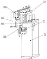
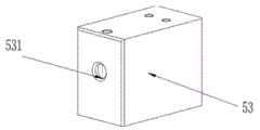
In a specific embodiment, further, the anti-overflow plug dust removal station 5 comprises a blowhead advancing cylinder 54, a blowhead fixing block 53 is arranged on one side of the blowhead advancing cylinder 54 close to the needle pressing jig 100, a blowing chamber 531 for accommodating the steel needle 15 and the anti-overflow plug 16 is arranged on the body of the blowhead fixing block 53, and an air pressure source is connected inside the blowing chamber 531; the blowhead advancing cylinder 54 operates to drive the blowhead fixing block 53 to advance and carry out dust blowing treatment on the steel needle 15 and the anti-overflow plug 16 which are arranged in the needle pressing jig 100; the blowing head advancing mechanism further comprises a blowing head advancing cylinder fixing frame 55 fixedly arranged at the bottom of the blowing head advancing cylinder 54, and the blowing head advancing cylinder fixing frame 55 is fixed on the machine table 12.
Preferably, the bottom of the blowhead fixing block 53 is provided with a dust removal box 51, the interior of the blowhead fixing block 53 is ensured to be communicated with the dust removal box 51, and the dust removal box 51 is used for collecting the dust on the anti-overflow plug 16 component.
In a specific embodiment, further, the anti-overflow plug positioning station 6 comprises an anti-overflow plug pushing block 61 and a pushing block advancing cylinder 63, the anti-overflow plug pushing block 61 is fixedly arranged on one side, close to the needle pressing jig 100, of the pushing block advancing cylinder 63, a pushing block protruding part 62 capable of contacting the anti-overflow plug 16 is installed on the anti-overflow plug pushing block 61, the pushing block protruding part 62 is arranged in a groove shape, the middle groove body is used for accommodating the steel needle 15, and the length of the groove body of the protruding part 62 can be not less than the length of the steel needle 15 with one end exposed after the pushing position of the anti-overflow plug 16; specifically, the pushing block advancing cylinder 63 operates to drive the anti-overflow plug pushing block 61 to move forward and push the anti-overflow plug 16 to a certain position through the pushing block protruding portion 62, and the pushing block advancing cylinder 63 is fixed on the machine table 12 through the pushing block advancing cylinder bracket 64.
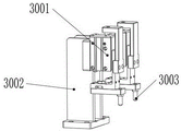
Fig. 21 shows, still includes the smelting tool and pushes down the device, the smelting tool pushes down the device and includes that the smelting tool pushes down positioning cylinder 3001, smelting tool and pushes down mounting 3002, the smelting tool pushes down positioning cylinder 3001 and passes through the smelting tool pushes down mounting 3002 and fixes on graduated disk 14, the smelting tool pushes down positioning cylinder 3001 bottom and installs the press head 3003 that can contact pressing needle smelting tool 100 and press the splenium 1002.
The specific work flow of the station is as follows: the pushing block advancing cylinder 63 pushes the pushing block protruding portion 62 to move forward to the position of the anti-overflow plug 16, at this time, the jig pushing-down positioning cylinder 3001 operates to drive the pressing head 3003 to press the pressing portion 1002 arranged at the upper portion of the needle pressing jig 100, so as to fix the steel needle 15, and then the pushing block protruding portion 62 starts to contact the anti-overflow plug 16 and performs a pushing action.
In a specific embodiment, the steel needle flattening station (7) further comprises a flattening workpiece 71 and a steel needle flattening cylinder 72, the steel needle flattening cylinder 72 drives the flattening workpiece 71 to act to flatten the steel needle 15, the steel needle flattening cylinder 72 is fixed on a steel needle flattening cylinder fixing member 73, and the steel needle flattening cylinder fixing member 73 is fixed on the machine table 12; in detail, the flattening workpieces 71 are arranged in pairs up and down and are used for flattening the position of the steel needle 15 where the needle handle 17 is subsequently installed, and when the needle handle 17 is assembled at a later station, the flattening position can be used for fixing the needle handle 17 and preventing the needle handle 17 from deflecting and sliding.
Also comprises a jig pressing device fixedly arranged on the dividing plate 14. The tool holding-down device provided by the tool holding-down device and the anti-overflow plug positioning device 6 have the same structure and function, and will not be described in detail again.
In a specific embodiment, further, the needle handle assembly station 8 comprises a needle handle feeding device, a needle handle pushing device and a steel needle clamping device, wherein the needle handle feeding device comprises a needle handle material vibrating disk 80 and a needle handle direct vibration 801, the needle handle material vibrating disk 80 conveys the needle handle 17 to the needle handle pushing device through the needle handle direct vibration 801, and the needle handle pushing device is provided with a needle handle positioning groove 813 for adjusting the angle and the position of the needle handle 17; the needle handle positioning grooves 813 are arranged at a certain angle, and the angle positions of the needle handles 17 passing through the needle handle positioning grooves 813 are unified, so that the needle handle clamping jaws 815 can conveniently clamp the needle handles, and the same deflection angle of the needle handles 17 arranged on the steel needle 15 can be ensured; the device is characterized by further comprising a needle handle clamping jaw cylinder 812, wherein a needle handle clamping jaw 815 for clamping the tail of the needle handle 17 is arranged on the needle handle clamping jaw cylinder 812, a needle handle transferring motor 811 is arranged at the back of the needle handle clamping jaw cylinder 812 and used for transferring and assembling the needle handle 17 clamped by the needle handle clamping jaw 815 to the steel needle 15, and the structural stability of the device can ensure that the angle of the device is kept unchanged in the assembling process of clamping the needle handle 17. The needle handle pushing device further comprises a needle handle distributing cylinder 814, and a material blocking block 816 is arranged on the needle handle distributing cylinder 814; the needle handle separating cylinder 814 operates to drive the material blocking block 816 to abut against the needle handle 17, so that the needle handle clamping jaw 815 can clamp the needle handle, and after the needle handle 17 is clamped, the needle handle separating cylinder 814 returns to the initial position, so that the conveying of the next needle handle 17 is not influenced.
Also comprises a steel needle clamping device fixedly arranged on the indexing disc 14. The structure and function of the needle holder are the same as those of the needle holder of the anti-overflow plug assembling device 4, and will not be described in detail herein.
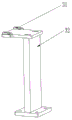
In a specific embodiment, further, the needle handle angle adjustment station (9) includes a needle handle angle adjustment cylinder 91, one end of the needle handle angle adjustment cylinder 91 near the needle pressing jig is provided with a needle handle limiting claw 92, the other end of the needle handle angle adjustment cylinder is fixedly connected with a needle handle angle adjustment cylinder fixing member 93, the bottom end of the needle handle angle adjustment cylinder fixing member 93 is provided with a needle handle angle adjustment advancing cylinder 94, and the needle handle angle adjustment advancing cylinder 94 is fixedly mounted on the machine 12.
Needle handle angle adjusting device 9 still is equipped with needle handle detection sensor 95, and needle handle detection sensor 95 installs directly over steel needle 15 position, and needle handle detection sensor 95 one end is fixed in body 1004 position on pressing needle smelting tool 100, makes its detection route pass through steel needle 15 needle handle 17 installation department, is convenient for detect. The needle handle detection sensor 95 is a photoelectric sensor, and detects whether the needle handle 17 is on the steel needle 15 in the needle pressing jig 100 at the station by using the light reflection principle, if the needle handle 17 exists, the steel needle is qualified, and if the needle handle 17 does not exist, the steel needle is defective; the photoelectric sensor transmits a detection signal of the presence or absence of the needle handle 17 on the steel needle 15 to the PLC controller, and the PLC controller controls the qualified product blanking device 10 and the defective product blanking device to perform corresponding actions.
The specific work flow of the station is as follows: the needle handle angle adjustment advance cylinder 94 operates to drive the needle handle angle adjustment cylinder 91 to move forward, and the needle handle angle adjustment cylinder 91 performs angle adjustment on the needle handle 17 fixed on the steel needle 15 in the steel needle jig 100 by the needle handle limiting claw 92 arranged at one end close to the needle pressing jig, so that the angles of the needle handle 17 are uniform and vertical downward.
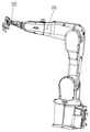
In a specific embodiment, further, the qualified product blanking device 10 includes a mechanical arm 101, one end of the mechanical arm 101 is installed on the machine 12, the other end of the mechanical arm is installed with a mechanical arm clamping jaw cylinder 102, a clamping jaw is installed on the mechanical arm clamping jaw cylinder 102 and used for clamping a qualified product after processing, and the mechanical arm 101 is the prior art and is not described in detail again.
In a specific embodiment, further, the defective product blanking station 11 includes a blanking clamping jaw 1101 and a blanking advancing cylinder 1103, one end of the blanking clamping jaw 1101 is connected with a blanking clamping jaw cylinder 1102 for driving the blanking clamping jaw 1101 to clamp and open, the blanking clamping jaw cylinder 1102 is connected with the blanking advancing cylinder 1103 in the vertical direction through a fixing member, and the blanking advancing cylinder 1103 is installed on the index plate 14 through a blanking advancing cylinder fixing member 1104.
Still including locating under the unloading clamping jaw 1101 and be used for collecting the waste product box 1105 of defective products, waste product box 1105 sets firmly on board 12.
The specific work flow of the station is as follows: the blanking advancing cylinder 1103 acts to drive the blanking clamping jaw 1101 to displace, and the blanking clamping jaw cylinder 1102 drives the blanking clamping jaw 1101 to clamp the defective product on the needle pressing jig 100 and discard the defective product into the waste box 1105.
Finally, it should also be noted that, herein, relational terms such as first and second, and the like may be used solely to distinguish one entity or action from another entity or action without necessarily requiring or implying any actual such relationship or order between such entities or actions. Also, the terms "comprises," "comprising," or any other variation thereof, are intended to cover a non-exclusive inclusion, such that a process, method, article, or apparatus that comprises a list of elements does not include only those elements but may include other elements not expressly listed or inherent to such process, method, article, or apparatus. Without further limitation, an element defined by the phrase "comprising an … …" does not exclude the presence of other identical elements in a process, method, article, or apparatus that comprises the element.
The embodiments in the present description are described in a progressive manner, each embodiment focuses on differences from other embodiments, and the same and similar parts among the embodiments are referred to each other.
The previous description of the disclosed embodiments is provided to enable any person skilled in the art to make or use the present invention. Various modifications to these embodiments will be readily apparent to those skilled in the art, and the generic principles defined herein may be applied to other embodiments without departing from the spirit or scope of the invention. Thus, the present invention is not intended to be limited to the embodiments shown herein but is to be accorded the widest scope consistent with the principles and novel features disclosed herein.
Claims (12)
1. The automatic equipment for assembling the Y-type remaining needle steel needle, the anti-overflow plug and the needle handle comprises a machine table and is characterized in that a steel needle automatic feeding station, a steel needle positioning station, a steel needle detection station, an anti-overflow plug assembling station, an anti-overflow plug dedusting station, an anti-overflow plug positioning station, a steel needle flattening station, a needle handle assembling station, a needle handle angle adjusting station, a qualified product blanking station and a defective product blanking station are sequentially arranged on the table top in an annular mode; in addition, an index plate is arranged right above the machine table and used for bearing the auxiliary device of the station, and the machine table and the index plate are fixedly connected through a connecting shaft; still including the delivery carousel, the delivery carousel is located on the connecting axle between board and the graduated disk, realize through mechanical pushing the delivery carousel is followed the connecting axle operation, wherein, the delivery carousel outside still is equipped with the tucking tool that carries out processing with the steel needle transmission to each station.
2. The automatic Y-type remaining needle steel needle assembling equipment with the anti-overflow plug and the needle handle is characterized in that the needle pressing jig comprises an upper body and a lower body, the upper body and the lower body are movably connected through a spring, the upper body is provided with a pressing portion, the lower body is provided with an ejector block, the steel needle can be arranged between the upper body and the ejector block, the pressing portion is pressed to fix the steel needle, and when the pressing is not performed, the steel needle is in sliding fit with the needle pressing jig.
3. The automatic equipment for assembling the Y-type remaining needle steel needle with the anti-overflow plug and the needle handle as claimed in claim 1, wherein the automatic steel needle feeding station comprises an ejection lifting cylinder and a material receiving lifting cylinder which are fixedly arranged on a machine table, an ejection rod is arranged at the top of the ejection lifting cylinder, the steel needle is ejected out of a storage bin arranged above the ejection rod through the ejection rod and is transferred to a material receiving tool arranged at the upper part of the material receiving lifting cylinder; one end of the receiving jig, which is close to the ejector rod, is provided with a needle lifting block for placing a steel needle; the needle lifting block is two protruding blocks arranged outside the material receiving jig and used for placing the front end and the rear end of the steel needle, and a space capable of containing an ejector rod is reserved between the two protruding blocks; a material receiving transverse moving cylinder is arranged between the material receiving lifting cylinder and the material receiving smelting tool; the material receiving transverse moving cylinder drives the needle lifting block on the material receiving jig to transversely move to the position of the material ejecting rod;
still press from both sides the device including getting, press from both sides the device and include steel needle clamping jaw cylinder, horizontal migration cylinder and horizontal migration cylinder mounting, steel needle clamping jaw cylinder one end is connected with the steel needle clamping jaw, and the other end passes through the connecting piece and links to each other with the horizontal migration cylinder, the horizontal migration cylinder sets firmly on the graduated disk through horizontal migration cylinder mounting, steel needle clamping jaw cylinder drive the steel needle clamping jaw will lift the steel needle on the needle piece and press from both sides and get the action, the operation of horizontal migration cylinder will the steel needle that the steel needle clamping jaw was pressed from both sides and is got shifts to in the pressing needle smelting tool.
4. The automatic assembly equipment for the Y-type remaining needle steel needle, the spill-proof plug and the needle handle according to claim 1, wherein the steel needle positioning station comprises an ejector pin cylinder and an ejector pin cylinder fixing piece, and the ejector pin cylinder is fixedly arranged on the machine table through the ejector pin cylinder fixing piece; the thimble cylinder is provided with a thimble head which pushes the steel needle in the needle pressing jig to a certain position.
5. The automatic Y-type remaining needle steel needle and spill-proof plug and needle handle assembling equipment according to claim 1, wherein the steel needle detection station comprises a steel needle detection sensor and a sensor fixing frame, the steel needle detection sensor is fixedly arranged on a machine table through the sensor fixing frame, and the steel needle detection sensor is used for detecting whether a steel needle exists in the needle pressing jig or not.
6. The automatic Y-type remaining needle steel needle and anti-overflow plug and needle handle assembly equipment as claimed in claim 1, wherein the anti-overflow plug assembly station comprises an anti-overflow plug feeding device, an anti-overflow plug dipping alcohol, a hole forming device and a steel needle clamping device, the anti-overflow plug feeding device comprises an anti-overflow plug vibrating disc, the anti-overflow plug vibrating disc conveys the anti-overflow plug to the anti-overflow plug dipping alcohol and hole forming device through anti-overflow plug direct vibration, the anti-overflow plug dipping alcohol and hole forming device comprises a first anti-overflow plug lifting cylinder, a second anti-overflow plug lifting cylinder and an anti-overflow plug assembly translation cylinder, the first anti-overflow plug lifting cylinder is connected with a first anti-overflow plug translation cylinder in a sliding manner, and the first anti-overflow plug translation cylinder and the second anti-overflow plug lifting cylinder are installed on the anti-overflow plug assembly translation cylinder together; the bottoms of the first anti-overflow plug lifting cylinder and the second anti-overflow plug lifting cylinder are respectively provided with a first anti-overflow plug clamping jaw and a second anti-overflow plug clamping jaw;
the anti-overflow plug dipping alcohol and tapping device further comprises an alcohol groove arranged corresponding to the first anti-overflow plug lifting cylinder and an anti-overflow plug tapping blade arranged corresponding to the second anti-overflow plug lifting cylinder, the tip end of the blade is provided with a tapping groove opposite to the position, the first anti-overflow plug lifting cylinder operates to clamp the anti-overflow plug conveyed on the vibration disc through the first anti-overflow plug clamping jaw, the anti-overflow plug is transferred to the alcohol groove to be dipped through the first anti-overflow plug translation cylinder, and the anti-overflow plug dipped in alcohol is transferred to the tapping groove through the anti-overflow plug assembling translation cylinder; the blade is fixed on the blade clamp, an anti-overflow plug hole opening cylinder is arranged at the bottom of the blade clamp, and the anti-overflow plug hole opening cylinder operates to drive the blade to move forwards to open a hole in the anti-overflow plug; a second anti-overflow plug clamping jaw arranged on the second anti-overflow plug lifting cylinder clamps the anti-overflow plug after the hole is opened, and the anti-overflow plug is transferred to an anti-overflow plug to-be-assembled clamp by the anti-overflow plug assembling translation cylinder; the bottom of the anti-overflow plug to-be-assembled clamp is connected with an anti-overflow plug to-be-assembled clamp propelling electric cylinder through a fixing piece, and the anti-overflow plug to-be-assembled clamp propelling electric cylinder drives the anti-overflow plug to-be-assembled clamp to move and assemble an anti-overflow plug onto a steel needle;
the steel needle clamping device comprises an upper clamping position and a lower clamping position, wherein the upper clamping position is fixedly arranged on the dividing plate, the lower clamping position is fixedly arranged on the machine table, the upper clamping position and the lower clamping position respectively comprise an upper clamping position cylinder and a lower clamping position cylinder, and clamping rods are respectively arranged at the bottom of the upper clamping position cylinder and on the upper portion of the lower clamping position cylinder.
7. The automatic equipment for assembling the Y-type remaining needle steel needle with the anti-overflow plug and the needle handle according to claim 1, wherein the anti-overflow plug dust removal station comprises a blowhead advancing cylinder, a blowhead fixing block is arranged on one side, close to the needle pressing jig, of the blowhead advancing cylinder, a blowing cavity for accommodating the steel needle and the anti-overflow plug is arranged on a blowhead fixing block body, and an air pressure source is connected inside the blowing cavity; the air blowing head advancing cylinder operates to drive the air blowing head fixing block to move forwards and carry out dust blowing treatment on a steel needle and an anti-overflow plug which are arranged in the needle pressing jig; the air blowing head device is characterized by further comprising a blowing head advancing cylinder fixing frame fixedly arranged at the bottom of the blowing head advancing cylinder, and the blowing head advancing cylinder fixing frame is fixed on the machine table.
8. The automatic assembly equipment of the Y-type remaining needle steel needle, the anti-overflow plug and the needle handle according to claim 1, wherein the anti-overflow plug positioning station comprises an anti-overflow plug pushing block and a pushing block advancing cylinder, the anti-overflow plug pushing block is fixedly arranged on one side, close to the needle pressing jig, of the pushing block advancing cylinder, the pushing block advancing cylinder operates to drive the anti-overflow plug pushing block to move forwards and push the anti-overflow plug on the steel needle to a certain position, and the pushing block advancing cylinder is fixed on a machine table through a pushing block advancing cylinder support;
still include the smelting tool and push down the device, the smelting tool pushes down the device and includes that the smelting tool pushes down positioning cylinder, smelting tool push down the mounting, the smelting tool pushes down positioning cylinder and passes through the smelting tool pushes down the mounting and fixes on the graduated disk, the smelting tool pushes down positioning cylinder bottom and installs the press head that can contact tucking tool smelting tool and press the splenium.
9. The automatic equipment for assembling the Y-type remaining needle steel needle with the anti-overflow plug and the needle handle according to claim 1, wherein the steel needle flattening station comprises a flattening workpiece and a steel needle flattening cylinder, the steel needle flattening cylinder drives the flattening workpiece to operate to flatten the steel needle, the steel needle flattening cylinder is fixed on a steel needle flattening cylinder fixing member, and the steel needle flattening cylinder fixing member is fixed on a machine table; also comprises a jig pressing device fixedly arranged on the index plate.
10. The automatic assembly equipment of the Y-type steel needle of the indwelling needle with the overflow prevention plug and the needle handle is characterized in that the needle handle assembly station comprises a needle handle feeding device, a needle handle pushing device and a steel needle clamping device, the needle handle feeding device comprises a needle handle material vibrating disk and a needle handle direct vibration, the needle handle material vibrating disk conveys the needle handle to the needle handle pushing device through the needle handle direct vibration, and the needle handle pushing device is provided with a needle handle positioning groove for adjusting the angle and the position of the needle handle; the needle handle clamping jaw air cylinder is provided with a needle handle clamping jaw for clamping the tail part of the needle handle, and the back part of the needle handle clamping jaw air cylinder is provided with a needle handle transferring motor set for transferring and assembling the needle handle clamped by the needle handle clamping jaw to a steel needle; also comprises a steel needle clamping device.
11. The automatic equipment for assembling the Y-type remaining needle steel needle with the anti-overflow plug and the needle handle according to claim 1, wherein the needle handle angle adjusting station comprises a needle handle angle adjusting cylinder, one end of the needle handle angle adjusting cylinder, which is close to the needle pressing jig, is provided with a needle handle limiting claw, the other end of the needle handle angle adjusting cylinder is fixedly connected with a needle handle angle adjusting cylinder fixing piece, the bottom end of the needle handle angle adjusting cylinder fixing piece is provided with a needle handle angle adjusting advancing cylinder, and the needle handle angle adjusting advancing cylinder is fixedly arranged on a machine table;
needle handle angle adjusting device still is equipped with needle handle detection sensor, needle handle detection sensor installs directly over the steel needle position, and needle handle detection sensor one end is fixed in body position on the tucking smelting tool.
12. The automatic equipment for assembling the Y-type remaining needle steel needle with the anti-overflow plug and the needle handle according to claim 1, wherein the defective product blanking station comprises a blanking clamping jaw and a blanking forward moving cylinder, one end of the blanking clamping jaw is connected with a blanking clamping jaw cylinder for driving the blanking clamping jaw to clamp and open, the blanking clamping jaw cylinder is connected with the blanking forward moving cylinder in the vertical direction through a fixing piece, and the blanking forward moving cylinder is installed on an index plate through a blanking forward moving cylinder fixing piece;
still including locating under the unloading clamping jaw and be used for collecting the waste product box of defective products, the waste product box sets firmly on the board.
Priority Applications (1)
| Application Number | Priority Date | Filing Date | Title |
|---|---|---|---|
| CN202120456523.2U CN214770248U (en) | 2021-03-03 | 2021-03-03 | Automatic device for assembling Y-type remaining needle steel needle, anti-overflow plug and needle handle |
Applications Claiming Priority (1)
| Application Number | Priority Date | Filing Date | Title |
|---|---|---|---|
| CN202120456523.2U CN214770248U (en) | 2021-03-03 | 2021-03-03 | Automatic device for assembling Y-type remaining needle steel needle, anti-overflow plug and needle handle |
Publications (1)
| Publication Number | Publication Date |
|---|---|
| CN214770248U true CN214770248U (en) | 2021-11-19 |
Family
ID=78755157
Family Applications (1)
| Application Number | Title | Priority Date | Filing Date |
|---|---|---|---|
| CN202120456523.2U Active CN214770248U (en) | 2021-03-03 | 2021-03-03 | Automatic device for assembling Y-type remaining needle steel needle, anti-overflow plug and needle handle |
Country Status (1)
| Country | Link |
|---|---|
| CN (1) | CN214770248U (en) |
-
2021
- 2021-03-03 CN CN202120456523.2U patent/CN214770248U/en active Active
Similar Documents
| Publication | Publication Date | Title |
|---|---|---|
| CN107170606B (en) | Automatic assembling machine for elastic sheet type waterproof switch | |
| CN110696416B (en) | Graphite bipolar plate molding system | |
| CN102189320A (en) | Automatic spot welding system | |
| CN107394275B (en) | Battery cell transfer piece welding machine | |
| CN107443659B (en) | A kind of wiper gear injection moulding apparatus | |
| CN211708605U (en) | Automatic assembling equipment for motor stator | |
| CN113478223B (en) | Automatic kludge of blade holder | |
| CN111002027A (en) | Automatic assembling equipment for motor stator | |
| CN211222178U (en) | Graphite bipolar plate compression molding system | |
| CN214770248U (en) | Automatic device for assembling Y-type remaining needle steel needle, anti-overflow plug and needle handle | |
| CN113923888A (en) | Conductive rubber assembly quality on circuit board | |
| CN113351523A (en) | Automatic detection device | |
| CN211840627U (en) | Automatic unloading pipe cutting machine of going up of high-efficient environmental protection | |
| CN111452371A (en) | Detection cleaning work station based on medical infusion line component assembling and detecting machine | |
| CN214770189U (en) | Be used for Y formula to keep somewhere needle steel needle and anti-overflow stopper assembly quality | |
| CN215588259U (en) | Welding device for supporting welding piece | |
| CN113732640A (en) | Automatic assembling equipment for automobile sun shield mirror assembly | |
| CN107336011B (en) | Third sideslip module of fuel pump automatic assembly line pulls out material assembly detecting system | |
| CN218856064U (en) | Be applied to location structure and general type nail post automatic installation device of nail post installation | |
| CN205985702U (en) | Connector automatically clamped assembly line | |
| CN215393138U (en) | Laser lobe of a leaf device | |
| CN115214080B (en) | High-precision injection molding system for nut implantation product | |
| CN217667669U (en) | Enclosing strip picking and assembling device | |
| CN218856063U (en) | Flexible mounting structure and general type nail post automatic installation device | |
| CN219026436U (en) | Automatic workpiece welding device |
Legal Events
| Date | Code | Title | Description |
|---|---|---|---|
| GR01 | Patent grant | ||
| GR01 | Patent grant |