CN214726258U - Injection mold is used in production of oil pipe thread protector - Google Patents
Injection mold is used in production of oil pipe thread protector Download PDFInfo
- Publication number
- CN214726258U CN214726258U CN202120085317.5U CN202120085317U CN214726258U CN 214726258 U CN214726258 U CN 214726258U CN 202120085317 U CN202120085317 U CN 202120085317U CN 214726258 U CN214726258 U CN 214726258U
- Authority
- CN
- China
- Prior art keywords
- main part
- department
- pipe
- workstation
- injection mold
- Prior art date
- Legal status (The legal status is an assumption and is not a legal conclusion. Google has not performed a legal analysis and makes no representation as to the accuracy of the status listed.)
- Expired - Fee Related
Links
- 238000002347 injection Methods 0.000 title claims abstract description 22
- 239000007924 injection Substances 0.000 title claims abstract description 22
- 230000001012 protector Effects 0.000 title claims abstract description 15
- 238000004519 manufacturing process Methods 0.000 title claims abstract description 13
- 238000001816 cooling Methods 0.000 claims abstract description 77
- 239000000463 material Substances 0.000 claims abstract description 33
- 230000017525 heat dissipation Effects 0.000 claims abstract description 7
- XLYOFNOQVPJJNP-UHFFFAOYSA-N water Substances O XLYOFNOQVPJJNP-UHFFFAOYSA-N 0.000 claims description 28
- 238000001746 injection moulding Methods 0.000 claims description 11
- RYGMFSIKBFXOCR-UHFFFAOYSA-N Copper Chemical compound [Cu] RYGMFSIKBFXOCR-UHFFFAOYSA-N 0.000 claims description 4
- 229910052802 copper Inorganic materials 0.000 claims description 4
- 239000010949 copper Substances 0.000 claims description 4
- 239000003208 petroleum Substances 0.000 claims 6
- 238000000465 moulding Methods 0.000 abstract description 3
- 229920003023 plastic Polymers 0.000 abstract description 3
- 239000004033 plastic Substances 0.000 abstract description 3
- 238000000926 separation method Methods 0.000 description 3
- 238000009423 ventilation Methods 0.000 description 3
- 229920000426 Microplastic Polymers 0.000 description 2
- 238000007664 blowing Methods 0.000 description 2
- 238000010438 heat treatment Methods 0.000 description 2
- 239000000155 melt Substances 0.000 description 2
- 239000000243 solution Substances 0.000 description 2
- 230000004075 alteration Effects 0.000 description 1
- 230000009286 beneficial effect Effects 0.000 description 1
- 238000004512 die casting Methods 0.000 description 1
- 238000000034 method Methods 0.000 description 1
- 238000012986 modification Methods 0.000 description 1
- 230000004048 modification Effects 0.000 description 1
- 230000002093 peripheral effect Effects 0.000 description 1
- 230000005855 radiation Effects 0.000 description 1
- 238000006467 substitution reaction Methods 0.000 description 1
- 239000002699 waste material Substances 0.000 description 1
Images


Abstract
The utility model discloses an injection mold is used in production of oil pipe thread protector, including the main part that is used for bearing workstation, the mould of mould, be used for carrying out the forced air cooling structure that forced air cooling handled and be used for carrying out the water-cooling structure that the water-cooling handled to the main part, the bottom of workstation is provided with the supporting leg, main part fixed mounting is in the upper end surface department of workstation, the recess that extends to in the interior is seted up in the top department of main part, forced air cooling structure fixed mounting is close to in its top department in the both sides of main part, water-cooling structure mounting is close to in the interior of its back one side department and main part in the upper end surface of workstation. The utility model discloses convenient to use, it is higher to the heat dissipation cooling efficiency of the material of moulding plastics, and heat dissipation cooling treatment uniformity is higher, and the effectual condition of appearing warping the damage because of the cooling is incomplete when having avoided the material drawing of patterns, then the effectual unnecessary loss of having avoided leading to the fact, the practicality is higher.
Description
Technical Field
The utility model relates to a mould field specifically is an injection mold is used in production of oil pipe thread protector.
Background
In short, the mold is a tool for manufacturing a molded article, the tool is composed of various parts, different molds are composed of different parts, the processing of the shape of the article is realized mainly by changing the physical state of the molded material, the types of the molds are various, the injection mold is one of the injection molds, the injection molding is a method for producing and molding an industrial product, the product usually adopts rubber injection molding and plastic injection molding, and the injection molding can also be divided into injection molding and die casting methods.
However, the existing injection mold has the following disadvantages:
(1) because injection mold is through heating the plastic granules that melts to two or three hundred degrees in injection molding machine the inside, then inject the inside of mould die cavity again, lead to it to use cooling system to cool off the processing to the material in follow-up needs, and current cooling system is lower to the cooling efficiency of material, and the cooling homogeneity is relatively poor, makes the deformation damage easily appear in the place that does not cool off completely, thereby leads to having reduced the whole production quality of work efficiency and material, and the practicality is relatively poor.
(2) When the demoulding operation is carried out, the time and the labor are wasted, and the efficiency is lower
SUMMERY OF THE UTILITY MODEL
An object of the utility model is to provide an injection mold is used in production of oil pipe thread protector, with solve traditional injection mold because injection mold is through heating the plastic granules that melts to two three hundred degrees in the injection molding machine the inside, then inject the inside of mould die cavity again, lead to it to come to cool off the processing to the material in follow-up needs, and current cooling system is lower to the cooling efficiency of material, and the cooling homogeneity is relatively poor, make the complete local deformation damage that easily appears of uncooled, thereby lead to having reduced the whole production quality of work efficiency and material, the practicality is relatively poor, and when carrying out drawing of patterns work, waste time and energy, the lower problem of efficiency.
In order to achieve the above object, the utility model provides a following technical scheme: the utility model provides an injection mold is used in production of oil pipe thread protector, is used for carrying out the forced air cooling structure that forced air cooling handled and be used for carrying out the water-cooling structure that the water-cooling was handled to the main part including the main part that is used for bearing workstation, mould, the bottom of workstation is provided with the supporting leg, main part fixed mounting is in the upper end surface department of workstation, the recess that extends to in the inside is seted up in the top department of main part, forced air cooling structure fixed mounting is close to in its top department in the both sides of main part, water-cooling structure mounting is close to in the inside in its back one side department and main part in the upper end surface of workstation, supplementary demoulding structure installs in the upper end surface of workstation and the inside groove department of main part.
Preferably, the forced air cooling structure includes mounting panel, fixed plate and radiator fan, mounting panel, fixed plate and radiator fan all are provided with two, two the mounting panel is fixed mounting respectively in the both sides department of main part, two the fixed plate is fixed mounting respectively in the upper end surface department of two mounting panels, two radiator fan is located in one side that two fixed plates are close to each other, and two through installed part fixed mounting radiator fan's level all is higher than the top height of main part.
Preferably, the two heat dissipation fans are arranged at oblique angles, and the wind directions of the two heat dissipation fans are consistent.
Preferably, the water-cooling structure includes water tank, circulating pipe, circulating pump and condenser, the water tank is installed in the upper end surface department of workstation, just the water tank is provided with water inlet and outlet, the both ends of circulating pipe are close to in its bottom and top department intercommunication with one side of water tank respectively and are connected, just the circulating pipe runs through the inside of main part, the part that the circulating pipe is located the main part is close to in the side and the bottom department all around of recess, circulating pump and condenser are all installed in the circulating pipe and are close to in the one end department of water tank bottom.
Preferably, the circulating pipe is made of copper materials.
Preferably, the part of the circulating pipe inside the main body is composed of a spiral pipe and an inclined S-shaped pipe, the spiral pipe is positioned at the periphery of the groove, and the S-shaped pipe is positioned at the bottom of the groove.
Preferably, the auxiliary demoulding structure comprises two groups of cylinders, two groups of connecting plates and two splicing plates, the cylinders are fixedly mounted at the upper end surface of the workbench, the telescopic ends of the cylinders penetrate through the bottoms of the two mounting plates respectively, the bottoms of the connecting plates are fixedly connected with the telescopic ends of the two cylinders respectively, the two splicing plates are L-shaped and are clamped inside the grooves respectively, injection molding pits are formed by the splicing plates and the grooves in a clamped mode, one sides of the splicing plates are fixedly connected with the connecting plates, and the upper end surface of the connecting plates is in height consistency with the top surface of the main body.
The utility model provides an injection mold is used in production of oil pipe thread protector possesses following beneficial effect:
(1) the utility model is provided with the air cooling structure and the water cooling structure, so that when the mold works, the continuous blowing and exhausting can be carried out on the groove of the mold by starting the two cooling fans to form the ventilation and heat dissipation circulation treatment, the material is preliminarily cooled, and simultaneously, the heat exchange can be carried out between the cooling circulation water circulating inside the circulation pipe and the heat of the groove inside the mold, so that the further cooling treatment can be carried out on the material, the cooling treatment efficiency on the material is effectively improved, the integral working efficiency is further improved, and the cooling uniformity of the material in the groove can be effectively improved due to the spiral pipe and the S-shaped pipe arranged on the circulation pipe, thereby effectively avoiding the deformation and damage of the material after the demolding caused by incomplete cooling of partial position, and further effectively avoiding the unnecessary loss, the practicability is higher.
(2) The utility model discloses a be provided with supplementary demoulding structure for when carrying out drawing of patterns work, can make its extension through starting the cylinder, drive the connecting plate and shift up, thereby drive the splice plate and shift up, and the splice plate shifts up and can drive the material after the cooling of moulding plastics and shift up, until it and the most separation of recess after, can artifical manual completion drawing of patterns fast and unload and handle, labour saving and time saving, efficiency is higher
Drawings
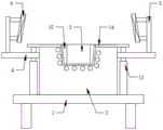
Fig. 1 is a schematic view of the overall structure of the present invention;
FIG. 2 is a side view of the water tank of the present invention;
FIG. 3 is a schematic view of the spiral tube structure of the present invention;
fig. 4 is a schematic structural view of an S-shaped pipe of the present invention.
FIG. 5 is a top view of the splice plate of the present invention
In the figure: 1. a work table; 2. a main body; 3. a groove; 4. mounting a plate; 5. a fixing plate; 6. a heat radiation fan; 7. a water tank; 8. a circulation pipe; 9. a circulation pump; 10. a condenser; 11. a spiral tube; 12. an S-shaped pipe; 13. a cylinder; 14. a connecting plate; 15. and (6) splicing plates.
Detailed Description
The technical solution in the embodiments of the present invention will be clearly and completely described below with reference to the accompanying drawings in the embodiments of the present invention.
As shown in fig. 1-5, the utility model provides a technical solution: the utility model provides an injection mold is used in production of oil pipe thread protector, is used for carrying out the forced air cooling structure that air-cooled cooling handled and be used for carrying out the water-cooled cooling structure that water-cooled cooling handled to main part 2 including the main part 2 that is used for bearing the mould to main part 1, the bottom of workstation 1 is provided with the supporting leg, 2 fixed mounting in the upper end surface department of workstation 1 of main part, the top department of main part 2 sets up the recess 3 that extends to in the interior, forced air cooling structure fixed mounting is close to in its top department in the both sides of main part 2, water-cooled cooling structure mounting is in the upper end surface of workstation 1 is close to in its back one side department and the inside of main part 2, supplementary demoulding structure installs in the upper end surface of workstation 1 and the inside recess 3 department of main part 2.
The air cooling structure comprises mounting plates 4, fixing plates 5 and cooling fans 6, wherein the number of the mounting plates 4, the fixing plates 5 and the cooling fans 6 is two, the two mounting plates 4 are respectively and fixedly mounted at two sides of the main body 2, the two fixing plates 5 are respectively and fixedly mounted at the upper end surfaces of the two mounting plates 4, the two cooling fans 6 are respectively and fixedly mounted at one sides of the two fixing plates 5 close to each other through mounting parts, and the horizontal heights of the two cooling fans 6 are higher than the top height of the main body 2, so that when the air cooling structure works, the two cooling fans 6 can be started to blow air and draw air at the groove 3 in the main body 2 to form ventilation circulation cooling treatment, and preliminary air cooling treatment is performed on materials;
the two cooling fans 6 are arranged in an inclined angle, and the wind directions of the two cooling fans 6 are consistent, so that the cooling fans 6 can better perform blowing and air draft circulation treatment on the groove 3;
the water-cooling structure comprises a water tank 7, a circulating pipe 8, a circulating pump 9 and a condenser 10, wherein the water tank 7 is arranged at the upper end surface of the workbench 1, the water tank 7 is provided with a water inlet and a water outlet, two ends of the circulating pipe 8 are respectively close to one side of the water tank 7 to be communicated and connected with the bottom end and the top end of the water tank, the circulating pipe 8 penetrates through the inside of the main body 2, the part of the circulating pipe 8 inside the main body 2 is close to the peripheral side surface and the bottom of the groove 3, the circulating pump 9 and the condenser 10 are both arranged at one end of the circulating pipe 8 close to the bottom of the water tank 7, so that when materials in the groove 3 are cooled by air cooling through the cooling fan 6, the circulating pump 9 and the condenser 10 can be started to pump the clean water added in the water tank 7 into the circulating pipe 8 in advance, and heat exchange is carried out by the spiral pipe 11 in the circulating pipe 8 and the heat at the periphery of the groove 3, the S-shaped pipe 12 in the circulating pipe 8 exchanges heat with heat at the bottom of the groove 3, so that water-cooling treatment is effectively carried out on the material in the groove 3, the heat exchange cooling treatment is uniform, the condition that the material is deformed and damaged due to incomplete cooling during demoulding is effectively avoided, unnecessary loss is effectively avoided, and the practicability is high;
the circulating pipe 8 is made of a copper material, and the copper material has good heat conductivity;
the part of the circulating pipe 8, which is positioned in the main body 2, consists of a spiral pipe 11 and an inclined S-shaped pipe 12, the spiral pipe 11 is positioned at the periphery of the groove 3, and the S-shaped pipe 12 is positioned at the bottom of the groove 3, so that the periphery of the groove 3 can be subjected to heat exchange cooling through the spiral pipe 11, and then the bottom of the groove 3 is subjected to heat exchange cooling through the S-shaped pipe 12, and the cooling uniformity of materials in the groove 3 is improved;
the auxiliary demoulding structure comprises two groups of cylinders 13, connecting plates 14 and splicing plates 15, wherein the two groups of auxiliary demoulding structures are arranged, the two cylinders 13 are fixedly arranged on the upper end surface of the workbench 1, the telescopic ends of the two cylinders 13 respectively penetrate through the bottoms of the two mounting plates 4, the bottoms of the two connecting plates 14 are respectively fixedly connected with the telescopic ends of the two cylinders 13, the two splicing plates 15 are L-shaped, the two splicing plates 15 are respectively clamped in the grooves 3, the splicing plates 15 are clamped with the grooves 3 to form injection molding pits, one sides of the splicing plates 15 are fixedly connected with the connecting plates 14, the upper end surfaces of the connecting plates 14 are consistent with the top surface of the main body 2 in height, so that when demoulding operation is carried out, the two cylinders 13 can be started to extend to drive the two connecting plates 14 and the two splicing plates 15 to move upwards, thereby drive the material after the injection molding cooling in recess 3 and shift up, until material and 3 most separation in recess, at this moment, can artifical manual quick the material of taking off, accomplish the drawing of patterns work of unloading, labour saving and time saving, efficiency is higher.
The working principle is as follows: when the device works, the two cooling fans 6 can be started to blow air and exhaust air at the groove 3 in the main body 2 to form ventilation circulation cooling treatment, so that primary air-cooling treatment is carried out on materials, meanwhile, clear water added in advance in the water tank 7 can be cooled and then pumped into the circulation pipe 8 by starting the circulation pump 9 and the condenser 10, heat exchange is carried out between the spiral pipe 11 in the circulation pipe 8 and heat at the periphery of the groove 3, heat exchange is carried out between the S-shaped pipe 12 in the circulation pipe 8 and heat at the bottom of the groove 3, so that the materials in the groove 3 are effectively subjected to water-cooling treatment, the heat exchange cooling treatment is uniform, the condition that the materials are deformed and damaged due to incomplete cooling during demoulding is effectively avoided, unnecessary loss is effectively avoided, the practicability is high, and finally, during demoulding work, can make its extension through starting two cylinders 13, drive and drive two connecting plates 14 and two splice plates 15 and move up to the material that drives after the injection cooling in recess 3 shifts up, until material and the most separation of recess 3, at this moment, can artifical manual material of taking off fast, the work of unloading of accomplishing the drawing of patterns, labour saving and time saving, efficiency is higher.
Although embodiments of the present invention have been shown and described, it will be appreciated by those skilled in the art that changes, modifications, substitutions and alterations can be made in these embodiments without departing from the principles and spirit of the invention, the scope of which is defined in the appended claims and their equivalents.
Claims (7)
1. The utility model provides an injection mold is used in production of oil pipe thread protector, is used for carrying out air-cooled cooling structure that air-cooled cooling handled, water-cooling structure and supplementary demoulding structure that water-cooled cooling handled to main part (2) including workstation (1) that are used for bearing the mould, main part (2) of mould, be used for carrying out air-cooled cooling to main part (2), its characterized in that: the bottom of workstation (1) is provided with the supporting leg, main part (2) fixed mounting is in the upper end surface department of workstation (1), recess (3) that extend to in the inside are seted up in the top department of main part (2), air-cooled cooling structure fixed mounting is close to in its top department in the both sides of main part (2), water-cooled cooling structure installs in the upper end surface of workstation (1) is close to in the inside in its back one side department and main part (2), supplementary demoulding structure installs in the upper end surface of workstation (1) and recess (3) department of main part (2) inside.
2. The injection mold for producing the thread protector of the petroleum pipe according to claim 1, characterized in that: air-cooled cooling structure includes mounting panel (4), fixed plate (5) and radiator fan (6), mounting panel (4), fixed plate (5) and radiator fan (6) all are provided with two, two mounting panel (4) fixed mounting is in the both sides department of main part (2), two fixed plate (5) fixed mounting is in the upper end surface department of two mounting panels (4) respectively, two radiator fan (6) are respectively through installed part fixed mounting in the one side department that two fixed plates (5) are close to each other, and two the level of radiator fan (6) all is higher than the top height of main part (2).
3. The injection mold for producing the thread protector of the petroleum pipe according to claim 2, characterized in that: the two heat dissipation fans (6) are arranged at oblique angles, and the wind directions of the two heat dissipation fans (6) are consistent.
4. The injection mold for producing the thread protector of the petroleum pipe according to claim 1, characterized in that: the water-cooling structure includes water tank (7), circulating pipe (8), circulating pump (9) and condenser (10), install in the upper end surface department of workstation (1) water tank (7), just water tank (7) are provided with water inlet and outlet, the both ends of circulating pipe (8) are close to in its bottom and top department intercommunication with one side of water tank (7) respectively and are connected, just circulating pipe (8) run through the inside of main part (2), the part that circulating pipe (8) are located main part (2) inside is close to in side and bottom department all around recess (3), circulating pump (9) and condenser (10) are all installed in circulating pipe (8) and are close to in the one end department of water tank (7) bottom.
5. The injection mold for producing the thread protector of the petroleum pipe according to claim 4, wherein: the circulating pipe (8) is made of copper materials.
6. The injection mold for producing the thread protector of the petroleum pipe according to claim 4, wherein: the part of the circulating pipe (8) located inside the main body (2) is composed of a spiral pipe (11) and an inclined S-shaped pipe (12), the spiral pipe (11) is located on the periphery of the groove (3), and the S-shaped pipe (12) is located at the bottom of the groove (3).
7. The injection mold for producing the thread protector of the petroleum pipe according to claim 1, characterized in that: the auxiliary demolding structure comprises air cylinders (13), a connecting plate (14) and splicing plates (15), the auxiliary demolding structure is provided with two groups, the two air cylinders (13) are fixedly installed at the upper end surface of the workbench (1), the telescopic ends of the air cylinders (13) penetrate through the bottoms of the two mounting plates (4) respectively, the bottom of the connecting plate (14) is fixedly connected with the telescopic ends of the two air cylinders (13) respectively, the two splicing plates (15) are L-shaped, the two splicing plates (15) are clamped in the grooves (3) respectively, clamping between the splicing plates (15) and the grooves (3) forms injection molding pits, one sides of the splicing plates (15) are fixedly connected with the connecting plate (14), and the upper end surfaces of the connecting plates (14) are consistent with the top surface of the main body (2).
Priority Applications (1)
| Application Number | Priority Date | Filing Date | Title |
|---|---|---|---|
| CN202120085317.5U CN214726258U (en) | 2021-01-13 | 2021-01-13 | Injection mold is used in production of oil pipe thread protector |
Applications Claiming Priority (1)
| Application Number | Priority Date | Filing Date | Title |
|---|---|---|---|
| CN202120085317.5U CN214726258U (en) | 2021-01-13 | 2021-01-13 | Injection mold is used in production of oil pipe thread protector |
Publications (1)
| Publication Number | Publication Date |
|---|---|
| CN214726258U true CN214726258U (en) | 2021-11-16 |
Family
ID=78637405
Family Applications (1)
| Application Number | Title | Priority Date | Filing Date |
|---|---|---|---|
| CN202120085317.5U Expired - Fee Related CN214726258U (en) | 2021-01-13 | 2021-01-13 | Injection mold is used in production of oil pipe thread protector |
Country Status (1)
| Country | Link |
|---|---|
| CN (1) | CN214726258U (en) |
-
2021
- 2021-01-13 CN CN202120085317.5U patent/CN214726258U/en not_active Expired - Fee Related
Similar Documents
| Publication | Publication Date | Title |
|---|---|---|
| CN211028036U (en) | Zinc alloy piece production mould that possesses rapid cooling function | |
| CN214726258U (en) | Injection mold is used in production of oil pipe thread protector | |
| CN211138026U (en) | Injection mold that radiating efficiency is high | |
| CN210436522U (en) | Injection mold | |
| CN213891045U (en) | Injection mold with heat dissipation function | |
| CN212443183U (en) | Metal part manufacturing die convenient for demolding | |
| CN218928455U (en) | Injection mold with heat dissipation mechanism | |
| CN218557832U (en) | Injection mold convenient to cooling drawing of patterns | |
| CN216176542U (en) | High-efficient aluminium part forming die | |
| CN218342722U (en) | But injection mold is used in plastic part preparation of fast demoulding | |
| CN220073005U (en) | Aluminum profile forming die plate structure | |
| CN214521734U (en) | Cooling device for mold machining | |
| CN220219763U (en) | Composite material pole demoulding device | |
| CN220784568U (en) | Quick vulcanization mold for shock insulation rubber support | |
| CN210791681U (en) | Cooling device is used in plastic mould processing | |
| CN216300078U (en) | But mould plastics with rapid cooling's mould device | |
| CN218227662U (en) | Injection mold convenient to heat dissipation | |
| CN213675018U (en) | Mould of step motor drive screw axle core | |
| CN220198470U (en) | High-cooling injection mold | |
| CN212266442U (en) | Culture plate production extrusion device | |
| CN213166384U (en) | Novel plastic mould drawing of patterns device | |
| CN218776941U (en) | Cooling structure of long-life mould | |
| CN220219466U (en) | Display housing injection mold convenient to drawing of patterns | |
| CN216267259U (en) | Avoid high thermal diffusivity injection mold frame of mould deformation | |
| CN219667389U (en) | Injection mold with heat dissipation mechanism |
Legal Events
| Date | Code | Title | Description |
|---|---|---|---|
| GR01 | Patent grant | ||
| GR01 | Patent grant | ||
| CF01 | Termination of patent right due to non-payment of annual fee |
Granted publication date: 20211116 |
|
| CF01 | Termination of patent right due to non-payment of annual fee |