CN214651634U - Centering device is used in production of small handcart tire - Google Patents
Centering device is used in production of small handcart tire Download PDFInfo
- Publication number
- CN214651634U CN214651634U CN202121201744.1U CN202121201744U CN214651634U CN 214651634 U CN214651634 U CN 214651634U CN 202121201744 U CN202121201744 U CN 202121201744U CN 214651634 U CN214651634 U CN 214651634U
- Authority
- CN
- China
- Prior art keywords
- fixed
- pair
- fixedly connected
- plate
- production
- Prior art date
- Legal status (The legal status is an assumption and is not a legal conclusion. Google has not performed a legal analysis and makes no representation as to the accuracy of the status listed.)
- Active
Links
Images


Landscapes
- Tyre Moulding (AREA)
Abstract
The utility model discloses a centering device is used in production of small handcart tire, including fixed chassis, a set of dead lever of the equal fixed connection of front side and well rear side in the fixed chassis top, a set of transverse guide of the equal fixed connection of two sets of dead lever left and right sides. The utility model discloses in, at first install on conveyor additional through with centering device, conveyor carries out the pile to the tire and carries, when through centering device, start first hydraulic component and second hydraulic component, two sets of hydraulic component stimulations, the second is to the medium plate to the inboard translation that carries out, the second is to the medium plate and is rotated on the column spinner of installing additional through the two-way rotary rod pulling linkage board of second, the rotation of linkage board, another a set of two-way rotary rod of rethread drives first pair of medium plate and passes through the horizontal translation of guide rail to the inboard, two sets of centering plates are to the inboard translation of inboard simultaneously, then through the catch bar, promote it to the central inboard tire, conveniently carry out the pile in later stage, be worth wideling popularize.
Description
Technical Field
The utility model relates to a centering device equipment technical field especially relates to a centering device is used in small handcart tire production.
Background
A tire is a ground-rolling circular ring-shaped elastic rubber article mounted on various vehicles or machines. Generally mounted on a metal rim, and is capable of supporting a vehicle body, buffering external impact, achieving contact with a road surface and ensuring the driving performance of a vehicle. Tires are often used under complex and severe conditions, which are subjected to various deformations, loads, forces and high and low temperature effects during running, and therefore must have high load-bearing, traction and cushioning properties. At the same time, high abrasion resistance and flexibility resistance, and low rolling resistance and heat build-up are also required.
After the tire is processed, a stacking procedure is required, and if the centering operation of tire conveying cannot be realized, the stacking efficiency and the stacking result are directly influenced.
Disclosure of Invention
The utility model aims at solving the defects existing in the prior art and providing a centering device for producing a small handcart tire.
In order to achieve the above purpose, the utility model adopts the following technical scheme: a centering device for producing a small cart tire comprises a fixed underframe, wherein a group of fixed rods are fixedly connected with the front side and the middle rear side in the top of the fixed underframe, a group of transverse guide rails are fixedly connected with the left and right sides of two groups of fixed rods, a group of limiting slide blocks are transversely and slidably connected with four groups of transverse guide rails, a second pair of middle plates are fixedly connected with the tops of two groups of limiting slide blocks on the left, a first pair of middle plates are fixedly connected with the tops of two groups of limiting slide blocks on the right, a plurality of groups of push rods are fixedly connected with the interiors of the first pair of middle plates and the second pair of middle plates, center fixed plates are fixedly connected with the centers of the tops of the two groups of fixed rods, fixed bearing seats are fixedly connected with the centers inside of the center fixed plates, rotating columns are rotatably connected with the center fixed plates through fixed bearing seats, linkage plates are fixedly connected with the upper parts of the rotating columns, and first bidirectional rotating rods are rotatably connected with the right sides of the tops of the linkage plates, linkage board top left side is rotated and is connected the two-way rotary rod of second, the rotary column other side end is rotated and is connected first pair of medium plate, the two-way rotary rod other side end of second is rotated and is connected the second and to the medium plate, fixed chassis top front side fixed connection second fixed block, the first hydraulic assembly of second fixed block left side fixed connection, the output fixed connection second of first hydraulic assembly is to the medium plate, the first fixed block of fixed chassis top rear side fixed connection, first fixed block left side fixed connection second hydraulic assembly, the output fixed connection second of second hydraulic assembly is to the medium plate.
As a further description of the above technical solution:
the left push rod longitudinally penetrates through the second pair of middle plates.
As a further description of the above technical solution:
the right push rod longitudinally penetrates through the first pair of middle plates.
As a further description of the above technical solution:
the fixed bearing seat longitudinally penetrates through the central fixed plate.
As a further description of the above technical solution:
the rotating column longitudinally penetrates through the linkage plate.
As a further description of the above technical solution:
the other side end of the first bidirectional rotating rod is rotatably connected to the middle part of the first middle plate pair.
As a further description of the above technical solution:
the other side end of the second bidirectional rotating rod is rotatably connected with the middle part of the second pair of middle plates.
The utility model discloses following beneficial effect has:
the utility model discloses in, at first install on conveyor additional through with centering device, conveyor carries out the pile to the tire and carries, when through centering device, start first hydraulic component and second hydraulic component, two sets of hydraulic component stimulations, the second is to the medium plate to the inboard translation that carries out, the second is to the medium plate and is rotated on the column spinner of installing additional through the two-way rotary rod pulling linkage board of second, the rotation of linkage board, another a set of two-way rotary rod of rethread drives first pair of medium plate and passes through the horizontal translation of guide rail to the inboard, two sets of centering plates are to the inboard translation of inboard simultaneously, then through the catch bar, promote it to the central inboard tire, conveniently carry out the pile in later stage, be worth wideling popularize.
Drawings
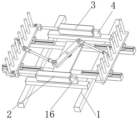
Fig. 1 is an isometric view of a centering device for producing a small cart tire according to the present invention;
fig. 2 is a front-rear two-angle axis measuring view of the centering device for producing the small cart tire provided by the utility model;
fig. 3 is a left side view of the centering device for producing a small handcart tire provided by the utility model.
Illustration of the drawings:
1. fixing the underframe; 2. a first hydraulic assembly; 3. a second hydraulic assembly; 4. a first fixed block; 5. a linkage plate; 6. a spin column; 7. a first bidirectional rotating rod; 8. a first pair of middle plates; 9. a push rod; 10. fixing a bearing seat; 11. a second bidirectional rotary rod; 12. a second pair of middle plates; 13. a central fixing plate; 14. a transverse guide rail; 15. a limiting slide block; 16. a second fixed block; 17. and (5) fixing the rod.
Detailed Description
The technical solutions in the embodiments of the present invention will be described clearly and completely with reference to the accompanying drawings in the embodiments of the present invention, and it is obvious that the described embodiments are only some embodiments of the present invention, not all embodiments. Based on the embodiments in the present invention, all other embodiments obtained by a person skilled in the art without creative work belong to the protection scope of the present invention.
In the description of the present invention, it should be noted that the terms "center", "upper", "lower", "left", "right", "vertical", "horizontal", "inner", "outer", and the like indicate orientations or positional relationships based on the orientations or positional relationships shown in the drawings, and are only for convenience of description and simplification of description, but do not indicate or imply that the device or element referred to must have a specific orientation, be constructed and operated in a specific orientation, and thus, should not be construed as limiting the present invention; the terms "first," "second," and "third" are used for descriptive purposes only and are not to be construed as indicating or implying relative importance, and furthermore, unless otherwise explicitly stated or limited, the terms "mounted," "connected," and "connected" are to be construed broadly and may be, for example, fixedly connected, detachably connected, or integrally connected; can be mechanically or electrically connected; they may be connected directly or indirectly through intervening media, or they may be interconnected between two elements. The specific meaning of the above terms in the present invention can be understood in specific cases to those skilled in the art.
Referring to fig. 1-3, the present invention provides an embodiment: a centering device for producing a small cart tire comprises a fixed chassis 1, wherein a group of fixed rods 17 are fixedly connected with the front side and the middle rear side in the top of the fixed chassis 1, a group of transverse guide rails 14 are fixedly connected with the left side and the right side of the two groups of fixed rods 17, four groups of transverse guide rails 14 are transversely and slidably connected with a group of limiting sliders 15, the top of the left two groups of limiting sliders 15 is fixedly connected with a second pair of middle plates 12, the top of the right two groups of limiting sliders 15 is fixedly connected with a first pair of middle plates 8, the insides of the first pair of middle plates 8 and the second pair of middle plates 12 are fixedly connected with a plurality of groups of push rods 9, the top centers of the two groups of fixed rods 17 are fixedly connected with a central fixed plate 13, the inside center of the central fixed plate 13 is fixedly connected with a fixed bearing seat 10, the inside of the fixed bearing seat 10 is fixedly connected with a rotary column 6, the upper part of the rotary column 6 is fixedly connected with a linkage plate 5, the right side of the top of a linkage plate 5 is rotatably connected with a first bidirectional rotating rod 7, the left side of the top of the linkage plate 5 is rotatably connected with a second bidirectional rotating rod 11, the other side of a rotating column 6 is rotatably connected with a first pair of middle plates 8, the other side of the second bidirectional rotating rod 11 is rotatably connected with a second pair of middle plates 12, the front side of the top of a fixed chassis 1 is fixedly connected with a second fixed block 16, the left side of the second fixed block 16 is fixedly connected with a first hydraulic assembly 2, the output end of the first hydraulic assembly 2 is fixedly connected with a second pair of middle plates 12, the rear side of the top of the fixed chassis 1 is fixedly connected with a first fixed block 4, the left side of the first fixed block 4 is fixedly connected with a second hydraulic assembly 3, the output end of the second hydraulic assembly 3 is fixedly connected with the second pair of middle plates 12, firstly, a centering device is additionally arranged on a conveying device, the conveying device is used for stacking and conveying tires, when the tires pass through the centering device, the first hydraulic assembly 2 and the second hydraulic assembly 3 are started, two sets of hydraulic assembly pulling, the second is to middle plate 12 to the inboard translation that carries on, the second is to middle plate 12 through 11 pulling linkage plates 5 of the two-way rotary rod of second on the column spinner 6 of installing additional rotatory, linkage plates 5's rotation, the rethread another a set of two-way rotary rod drives first pair of middle plate 8 and passes through the horizontal translation of guide rail inboard side, two sets of to middle plate are to the inboard translation simultaneously, then through catch bar 9, with the tire to central inboard promotion to it, the pile in later stage is conveniently carried out.
The left pushing rod 9 longitudinally penetrates through the second pair of middle plates 12, the right pushing rod 9 longitudinally penetrates through the first pair of middle plates 8, the fixed bearing seat 10 longitudinally penetrates through the central fixed plate 13, the rotating column 6 longitudinally penetrates through the linkage plate 5, the other side end of the first bidirectional rotating rod 7 is rotatably connected to the middle of the first pair of middle plates 8, and the other side end of the second bidirectional rotating rod 11 is rotatably connected to the middle of the second pair of middle plates 12.
The working principle is as follows: at first through install centering device additional on conveyor, conveyor carries out the pile transport to the tire, when through centering device, start first hydraulic component 2 and second hydraulic component 3, two sets of hydraulic component pulling, the second is to medium plate 12 inboard translation, the second is to medium plate 12 through 11 pulling linkage plates 5 of second two-way rotary rod on the column spinner 6 of installing additional rotatory, linkage plates 5's rotation, another set of two-way rotary rod of rethread drives first pair of medium plate 8 and passes through the horizontal translation of guide rail inboard, two sets of centering plates are inboard translation to the side simultaneously, then through catch bar 9, promote it to it with the tire inboard central, conveniently carry out the pile in later stage.
Finally, it should be noted that: although the present invention has been described in detail with reference to the foregoing embodiments, it will be apparent to those skilled in the art that modifications and variations can be made in the embodiments or in part of the technical features of the embodiments without departing from the spirit and the principles of the present invention.
Claims (7)
1. The utility model provides a centring means is used in production of small handcart tire, includes fixed chassis (1), its characterized in that: the front side and the middle rear side in the top of a fixed chassis (1) are fixedly connected with a group of fixed rods (17), the left side and the right side of the two groups of fixed rods (17) are fixedly connected with a group of transverse guide rails (14), the four groups of transverse guide rails (14) are transversely connected with a group of limit sliders (15), the top of the left two groups of limit sliders (15) is fixedly connected with a second pair of middle plates (12), the top of the right two groups of limit sliders (15) is fixedly connected with a first pair of middle plates (8), the insides of the first pair of middle plates (8) and the second pair of middle plates (12) are fixedly connected with a plurality of groups of push rods (9), the top centers of the two groups of fixed rods (17) are fixedly connected with a central fixed plate (13), the inside center of the central fixed plate (13) is fixedly connected with a fixed bearing seat (10), the inside of the fixed bearing seat (10) is fixedly connected with a rotary column (6), and the central fixed plate (13) is rotatably connected with the rotary column (6) through the fixed bearing seat (10), column spinner (6) upper portion fixed connection linkage plate (5), linkage plate (5) top right side is rotated and is connected first bidirectional rotating rod (7), linkage plate (5) top left side is rotated and is connected second bidirectional rotating rod (11), column spinner (6) other side is rotated and is connected first pair of medium plate (8), second bidirectional rotating rod (11) other side is rotated and is connected second pair of medium plate (12), fixed chassis (1) top front side fixed connection second fixed block (16), second fixed block (16) left side fixed connection first hydraulic assembly (2), the output fixed connection second of first hydraulic assembly (2) is to medium plate (12), fixed chassis (1) top rear side fixed connection first fixed block (4), first fixed block (4) left side fixed connection second hydraulic assembly (3), the output fixed connection second of second hydraulic assembly (3) is to medium plate (12).
2. A centring device for the production of tyres for trolleys according to claim 1, characterized in that: the left push rod (9) longitudinally penetrates through the second pair of middle plates (12).
3. A centring device for the production of tyres for trolleys according to claim 1, characterized in that: the right push rod (9) longitudinally penetrates through the first pair of middle plates (8).
4. A centring device for the production of tyres for trolleys according to claim 1, characterized in that: the fixed bearing seat (10) longitudinally penetrates through the central fixed plate (13).
5. A centring device for the production of tyres for trolleys according to claim 1, characterized in that: the rotating column (6) longitudinally penetrates through the linkage plate (5).
6. A centring device for the production of tyres for trolleys according to claim 1, characterized in that: the other side end of the first bidirectional rotating rod (7) is rotatably connected with the middle part of the first pair of middle plates (8).
7. A centring device for the production of tyres for trolleys according to claim 1, characterized in that: the other side end of the second bidirectional rotating rod (11) is rotatably connected to the middle part of the second pair of middle plates (12).
Priority Applications (1)
| Application Number | Priority Date | Filing Date | Title |
|---|---|---|---|
| CN202121201744.1U CN214651634U (en) | 2021-06-01 | 2021-06-01 | Centering device is used in production of small handcart tire |
Applications Claiming Priority (1)
| Application Number | Priority Date | Filing Date | Title |
|---|---|---|---|
| CN202121201744.1U CN214651634U (en) | 2021-06-01 | 2021-06-01 | Centering device is used in production of small handcart tire |
Publications (1)
| Publication Number | Publication Date |
|---|---|
| CN214651634U true CN214651634U (en) | 2021-11-09 |
Family
ID=78486459
Family Applications (1)
| Application Number | Title | Priority Date | Filing Date |
|---|---|---|---|
| CN202121201744.1U Active CN214651634U (en) | 2021-06-01 | 2021-06-01 | Centering device is used in production of small handcart tire |
Country Status (1)
| Country | Link |
|---|---|
| CN (1) | CN214651634U (en) |
Cited By (1)
| Publication number | Priority date | Publication date | Assignee | Title |
|---|---|---|---|---|
| CN114909375A (en) * | 2022-04-01 | 2022-08-16 | 上海星豪燊汽车技术服务有限公司 | Supporting structure for automobile inner top plate and using method thereof |
-
2021
- 2021-06-01 CN CN202121201744.1U patent/CN214651634U/en active Active
Cited By (1)
| Publication number | Priority date | Publication date | Assignee | Title |
|---|---|---|---|---|
| CN114909375A (en) * | 2022-04-01 | 2022-08-16 | 上海星豪燊汽车技术服务有限公司 | Supporting structure for automobile inner top plate and using method thereof |
Similar Documents
| Publication | Publication Date | Title |
|---|---|---|
| CN214651634U (en) | Centering device is used in production of small handcart tire | |
| CN107876464A (en) | A kind of tire cleaning device | |
| CN112209293B (en) | Bearing frame for short-distance transfer of rail vehicle wheel sets to be repaired | |
| CN112895970B (en) | Full-automatic battery replacement equipment for automobile | |
| CN206826321U (en) | Chucking device | |
| CN206187162U (en) | Automatic car device that connects of heavy load double embrace child formula | |
| CN206202376U (en) | Mould rapid transport go-cart | |
| CN206255805U (en) | hydraulic lifting vehicle | |
| CN210714015U (en) | Carry sweep formula transfer robot | |
| CN109733816B (en) | Trolley | |
| CN219316550U (en) | Horizontal carrier for vehicle | |
| CN215045318U (en) | Tire buckle carrying and installing mechanism | |
| CN206477644U (en) | The vehicle shifting device of multi-storied garage | |
| CN113370065A (en) | High-strength corrosion-resistant polishing device for inner wall of steel bushing of steering knuckle | |
| CN211465398U (en) | Gas bottle loading system and translation frock | |
| CN214643125U (en) | Positioning tool for machining small cart tire | |
| CN216104513U (en) | Automobile tire conveyer | |
| CN220884404U (en) | Rubber tube vulcanizes transfer car (buggy) | |
| CN221215815U (en) | 6 Round RGV devices that suitable track of heavy load goods was gone | |
| CN221851243U (en) | Conveying device for tire processing | |
| CN219749812U (en) | Loading reinforcement device of railway transportation wheel type equipment | |
| CN214823404U (en) | Tire blank conveying device | |
| CN220905156U (en) | Wheel fixing device | |
| CN221458858U (en) | Metal support for tyre assembly | |
| CN219838048U (en) | Adjustable tire ring cutting machine |
Legal Events
| Date | Code | Title | Description |
|---|---|---|---|
| GR01 | Patent grant | ||
| GR01 | Patent grant |