CN214604686U - Circuit board edge cutting jig - Google Patents
Circuit board edge cutting jig Download PDFInfo
- Publication number
- CN214604686U CN214604686U CN202120225152.7U CN202120225152U CN214604686U CN 214604686 U CN214604686 U CN 214604686U CN 202120225152 U CN202120225152 U CN 202120225152U CN 214604686 U CN214604686 U CN 214604686U
- Authority
- CN
- China
- Prior art keywords
- fixed
- mounting
- fixed mounting
- edge cutting
- plate
- Prior art date
- Legal status (The legal status is an assumption and is not a legal conclusion. Google has not performed a legal analysis and makes no representation as to the accuracy of the status listed.)
- Active
Links
Images


Abstract
The utility model discloses a circuit board edge cutting jig, the on-line screen storage device comprises a base, the equal fixed mounting in both sides at base top has the curb plate, the top of base is through two curb plate fixed mounting has the roof, two the top fixed mounting of the relative one side lateral wall of curb plate has two guide rails, two equal movable sleeve joint on the guide rail installs the sliding sleeve, two fixed mounting has the connecting block between the sliding sleeve, and wherein one fixed mounting has first cylinder on the lateral wall of curb plate one side, first cylinder is located two between the guide rail, the output of first cylinder is provided with first pneumatic telescoping rod, first pneumatic telescoping rod's one end with connecting block fixed connection, one of them the bottom fixed mounting of sliding sleeve has first fixed plate. The utility model discloses a set up a series of structures and make this device have the dust sweeps that is convenient for produce when cutting edge and collect and carry out the characteristics fixed to the circuit board of different models size.
Description
Technical Field
The utility model relates to a circuit board processing technology field specifically is a circuit board flange cutting jig.
Background
The circuit board has the name: ceramic circuit board, alumina ceramic circuit board, aluminum nitride ceramic circuit board, PCB board, aluminum substrate, high frequency board, thick copper board, impedance board, PCB, ultra-thin circuit board, printed (copper etching technology) circuit board, etc. The circuit board enables the circuit to be miniaturized and visualized, and plays an important role in batch production of fixed circuits and optimization of electric appliance layout.
The circuit board is at the in-process of production, need cut edge its according to actual demand and handle, but current side cut tool is not convenient for fix the circuit board of different models, and easily produces the dust when cutting edge, cuts edge the back and is not convenient for collect the dust that produces when cutting edge, consequently, we have proposed a circuit board flange cutting tool solution problem in order to solve this a series of problems.
SUMMERY OF THE UTILITY MODEL
An object of the utility model is to provide a circuit board flange cutting tool to solve the problem that proposes among the above-mentioned background art.
In order to achieve the above object, the utility model provides a following technical scheme: a circuit board edge cutting jig comprises a base, wherein side plates are fixedly arranged on two sides of the top of the base, a top plate is fixedly arranged on the top of the base through two side plates, two guide rails are fixedly arranged above the side wall of one side of the two side plates opposite to each other, sliding sleeves are movably sleeved on the two guide rails, a connecting block is fixedly arranged between the two sliding sleeves, a first air cylinder is fixedly arranged on the side wall of one side of the side plate and positioned between the two guide rails, a first air telescopic rod is arranged at the output end of the first air cylinder, one end of the first air telescopic rod is fixedly connected with the connecting block, a first fixing plate is fixedly arranged at the bottom of one sliding sleeve, a second air cylinder is fixedly arranged at the bottom of the first fixing plate, and a second air telescopic rod is arranged at the output end of the second air cylinder, the bottom end of the second pneumatic telescopic rod is fixedly provided with a second fixed plate, the bottom of the second fixed plate is provided with a mounting frame, the inner side of the mounting frame is movably provided with a mounting shaft, the mounting shaft is fixedly sleeved with a cutting disc, one side of the mounting frame is fixedly provided with a driving motor, one end of the mounting shaft is fixedly connected with the output end of the driving motor, a trimming table is fixedly arranged at the middle position of the top of the base, one side of the top of the trimming table is fixedly provided with a fixed right-angle frame, the middle position of one side inside the trimming table is provided with a mounting groove, the mounting groove is of a one-side opening structure, the other side of the mounting groove is provided with a bearing, a threaded rotating shaft is movably arranged inside the mounting groove through the bearing, an internal threaded sleeve is sleeved on the threaded rotating shaft, and the top of the mounting groove is provided with a notch, the top of the internal thread sleeve is fixedly provided with a fixed column, the top end of the fixed column extends to the outer side of the top of the trimming platform through the notch, and the top end of the fixed column is fixedly provided with a movable right-angle frame.
Preferably, threaded through holes are formed in the two sides of the tops of the fixed right-angle frame and the movable right-angle frame, four threaded through holes are internally provided with screw rods in a threaded mode, knobs are arranged at the top ends of the screw rods, and pressing plates are arranged at the bottom ends of the screw rods.
Preferably, one side of the top of the trimming table is provided with a trimming groove, and the trimming groove is positioned under the cutting disc.
Preferably, the bottom of the pressing plate is provided with a rubber pad, and the rubber pad is fixedly bonded with the pressing plate through a strong glue.
Preferably, an axle seat is fixedly mounted inside the opening of the mounting groove, one end of the threaded rotating shaft is connected with a connecting rod through the axle seat, and a hand wheel is arranged at one end of the connecting rod.
Preferably, a dust collection fan is fixedly mounted on one side of the top of the second fixing plate, a metal corrugated pipe is arranged on one side of the dust collection fan, a dust collection head is arranged at one end of the metal corrugated pipe, an air outlet pipe is arranged on the other side of the dust collection fan, one end of the air outlet pipe is connected with a hose, a dust collection box is fixedly mounted on the side wall of one side of one of the side plates, and the other end of the hose is communicated with the inside of the dust collection box.
Compared with the prior art, the beneficial effects of the utility model are that: the utility model has the advantages of scientific and reasonable structure, convenient and safe use, the circuit board that needs to be trimmed is placed at the top of the trimming platform, according to the actual size, the hand wheel is rotated to drive the thread rotating shaft to rotate, the thread rotating shaft drives the internal thread sleeve to move, the internal thread sleeve drives the movable right-angle frame to move through the fixed column, the distance between the movable right-angle frame and the fixed right-angle frame is further adjusted, then four knobs are respectively rotated to enable four screw rods to fix the circuit board through the pressing plate, the device is further made to have strong adaptability when in use, circuit boards with different sizes and models are convenient to fix, the stability is strong when trimming, the second cylinder is controlled to drive the second pneumatic telescopic rod to move, the second cylinder is further made to push the cutting disc to move downwards to contact with the circuit board, and the driving motor is controlled to make the cutting disc rotate, the circuit board is cut, simultaneously, make first pneumatic telescopic link of first cylinder drive promote the cutting disc and remove, cut edge the processing to the circuit board, and in the side cut, control dust absorption fan for the dust sweeps that produces when dust absorption fan will cut edge inhales the inside of dust collection box, and then makes this device can effectually collect sweeps and the dust that produces when cutting edge.
Drawings
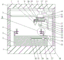
Fig. 1 is a schematic structural view of the whole of the present invention;
FIG. 2 is an enlarged view of the present invention at A in FIG. 1;
fig. 3 is a top view of the middle trimming table of the present invention.
In the figure: 1. a base; 2. trimming platforms; 3. a side plate; 4. fixing a right-angle frame; 5. a guide rail; 6. a top plate; 7. a dust collection head; 8. a metal bellows; 9. a dust collection fan; 10. connecting blocks; 11. a sliding sleeve; 12. a first pneumatic telescopic rod; 13. a first cylinder; 14. a first fixing plate; 15. a second cylinder; 16. an air outlet pipe; 17. a hose; 18. a second pneumatic telescopic rod; 19. a dust collection box; 20. a mounting frame; 21. a drive motor; 22. cutting the disc; 23. a movable right-angle frame; 24. a hand wheel; 25. a connecting rod; 26. a shaft seat; 27. fixing a column; 28. an internal thread sleeve; 29. mounting grooves; 30. a bearing; 31. a threaded shaft; 32. a rubber pad; 33. pressing a plate; 34. a threaded through hole; 35. a screw; 36. a knob; 37. a notch; 38. cutting an edge groove; 39. and a second fixing plate.
Detailed Description
The technical solutions in the embodiments of the present invention will be described clearly and completely with reference to the accompanying drawings in the embodiments of the present invention, and it is obvious that the described embodiments are only some embodiments of the present invention, not all embodiments. Based on the embodiments in the present invention, all other embodiments obtained by a person skilled in the art without creative work belong to the protection scope of the present invention.
Referring to fig. 1-3, the present invention provides a technical solution: a technical scheme of a circuit board edge cutting jig comprises a base 1, wherein two sides of the top of the base 1 are fixedly provided with side plates 3, the top of the base 1 is fixedly provided with a top plate 6 through the two side plates 3, two guide rails 5 are fixedly arranged above the side wall of one side opposite to the two side plates 3, the two guide rails 5 are movably sleeved with sliding sleeves 11, a connecting block 10 is fixedly arranged between the two sliding sleeves 11, a first air cylinder 13 is fixedly arranged on the side wall of one side plate 3, the first air cylinder 13 is positioned between the two guide rails 5, the output end of the first air cylinder 13 is provided with a first pneumatic telescopic rod 12, one end of the first pneumatic telescopic rod 12 is fixedly connected with the connecting block 10, the bottom of one sliding sleeve 11 is fixedly provided with a first fixing plate 14, the bottom of the first fixing plate 14 is fixedly provided with a second air cylinder 15, and the output end of the second air cylinder 15 is provided with a second pneumatic telescopic rod 18, a second fixing plate 39 is fixedly arranged at the bottom end of the second pneumatic telescopic rod 18, a mounting frame 20 is arranged at the bottom of the second fixing plate 39, a mounting shaft is movably arranged at the inner side of the mounting frame 20, a cutting disc 22 is fixedly sleeved on the mounting shaft, a driving motor 21 is fixedly arranged at one side of the mounting frame 20, one end of the mounting shaft is fixedly connected with the output end of the driving motor 21, a trimming table 2 is fixedly arranged at the middle position of the top of the base 1, a fixing right-angle frame 4 is fixedly arranged at one side of the top of the trimming table 2, a mounting groove 29 is formed at the middle position of one side inside the trimming table 2, the mounting groove 29 is of a one-side opening structure, a bearing 30 is arranged at the other side of the mounting groove 29, a threaded rotating shaft 31 is movably arranged inside the mounting groove 29 through the bearing 30, an internal thread sleeve 28 is sleeved on the threaded rotating shaft 31, and a notch 37 is formed at the top of the mounting groove 29, the top of the internal thread sleeve 28 is fixedly provided with a fixing column 27, the top end of the fixing column 27 extends to the outer side of the top of the trimming platform 2 through a notch 37, and the top end of the fixing column 27 is fixedly provided with a movable right-angle stand 23.
Preferably, threaded through holes 34 are formed in the two sides of the tops of the fixed right-angle frame 4 and the movable right-angle frame 23, screw rods 35 are installed on the inner equal threads of the four threaded through holes 34, knobs 36 are arranged on the top ends of the screw rods 35, pressing plates 33 are arranged at the bottom ends of the screw rods 35, and accordingly the circuit board is convenient to fix.
Preferably, the trimming groove 38 has been seted up to one side at side cut platform 2 top, and trimming groove 38 is located cutting disc 22 under for this device reasonable in design, cutting disc 22 can not contact with side cut platform 2 when cutting the circuit board, prevents that damage from appearing in side cut platform 2.
Preferably, the bottom of the pressing plate 33 is provided with a rubber pad 32, and the rubber pad 32 and the pressing plate 33 are fixed by bonding with a strong adhesive to prevent the pressing plate 33 from crushing the circuit board.
Preferably, an axle seat 26 is fixedly installed inside an opening of the installation groove 29, one end of the threaded rotating shaft 31 is connected with a connecting rod 25 through the axle seat 26, and one end of the connecting rod 25 is provided with a hand wheel 24, so that the threaded rotating shaft 31 can rotate conveniently to drive the internal thread sleeve 28 to move.
Preferably, a dust collection fan 9 is fixedly mounted on one side of the top of the second fixing plate 39, a metal corrugated pipe 8 is arranged on one side of the dust collection fan 9, a dust collection head 7 is arranged at one end of the metal corrugated pipe 8, an air outlet pipe 16 is arranged on the other side of the dust collection fan 9, one end of the air outlet pipe 16 is connected with a hose 17, a dust collection box 19 is fixedly mounted on the side wall of one side plate 3, the other end of the hose 17 is communicated with the inside of the dust collection box 19, the position of the dust collection head 7 can be adjusted through the metal corrugated pipe 8, the dust collection head is aligned to the cutting disc 22, the dust collection efficiency is further enhanced, the dust collection fan 9 is controlled, dust and waste generated when the dust collection fan 9 is used for cutting edges, and the waste and dust generated when the edges are effectively collected by the device.
The working principle is as follows: before use, the safety of each structure of the device is checked, wherein the driving motor 21, the first air cylinder 13, the second air cylinder 14 and the dust suction fan 9 are all existing electric elements, the electric elements can be installed and used according to actual use requirements, a circuit board to be subjected to edge cutting treatment is placed at the top of the edge cutting table 2, the hand wheel 24 is rotated according to the actual size of the electric elements, the hand wheel 24 drives the threaded rotating shaft 31 to rotate, the threaded rotating shaft 31 drives the internal threaded sleeve 28 to move, the internal threaded sleeve 28 drives the movable right-angle frame 23 to move through the fixed column 27, the distance between the movable right-angle frame 23 and the fixed right-angle frame 4 is adjusted, the four knobs 36 are respectively rotated, the circuit board is fixed through the pressing plates 33 by the four screw rods 35, the second air cylinder 15 is controlled, the second air cylinder 15 drives the second air telescopic rod 18 to move, and then the cutting disc 22 is pushed to move downwards to be in contact with the circuit board, and controlling the driving motor 21 again to rotate the cutting disc 22, cutting the circuit board, simultaneously, driving the first pneumatic telescopic rod 12 by the first cylinder 13 to push the cutting disc 22 to move, trimming the circuit board, controlling the dust collection fan 9 while trimming, sucking dust and sweeps generated when the dust collection fan 9 trims the edges into the dust collection box 19, and collecting the sweeps and the dust generated when trimming the edges effectively.
It is noted that, herein, relational terms such as first and second, and the like may be used solely to distinguish one entity or action from another entity or action without necessarily requiring or implying any actual such relationship or order between such entities or actions. Moreover, the terms "comprises," "comprising," or any other variation thereof, are intended to cover a non-exclusive inclusion, such that a process, method, article, or apparatus that comprises a list of elements does not include only those elements but may include other elements not expressly listed or inherent to such process, method, article, or apparatus, and any standard components found in known art that may be commercially available or commercially available and may be readily customized based on the teachings of the specification and the drawings, and that the particular connection between the various components is by conventional means well known in the art, and that the machine, component, or apparatus is by model and circuit connection is by conventional means well known in the art, and will not be described in detail herein.
Although embodiments of the present invention have been shown and described, it will be appreciated by those skilled in the art that changes, modifications, substitutions and alterations can be made in these embodiments without departing from the principles and spirit of the invention, the scope of which is defined in the appended claims and their equivalents.
Claims (6)
1. The utility model provides a circuit board edge cutting tool, includes base (1), its characterized in that: the pneumatic telescopic handle is characterized in that side plates (3) are fixedly mounted on two sides of the top of the base (1), a top plate (6) is fixedly mounted on the top of the base (1) through the two side plates (3), two guide rails (5) are fixedly mounted above the side wall of one side of the two side plates (3), two sliding sleeves (11) are movably sleeved on the two guide rails (5), a connecting block (10) is fixedly mounted between the two sliding sleeves (11), a first cylinder (13) is fixedly mounted on the side wall of one side plate (3), the first cylinder (13) is positioned between the two guide rails (5), a first pneumatic telescopic rod (12) is arranged at the output end of the first cylinder (13), one end of the first pneumatic telescopic rod (12) is fixedly connected with the connecting block (10), and a first fixing plate (14) is fixedly mounted at the bottom of one sliding sleeve (11), the bottom fixed mounting of first fixed plate (14) has second cylinder (15), the output of second cylinder (15) is provided with second pneumatic telescopic link (18), the bottom fixed mounting of second pneumatic telescopic link (18) has second fixed plate (39), the bottom of second fixed plate (39) is provided with mounting bracket (20), the inboard movable mounting of mounting bracket (20) has the installation axle, fixed sleeve installs cutting disc (22) on the installation axle, just one side fixed mounting of mounting bracket (20) has driving motor (21), the one end of installation axle with the output fixed connection of driving motor (21), the intermediate position department fixed mounting at base (1) top has side cut platform (2), one side fixed mounting at side of side cut platform (2) top has fixed mounting (4), the intermediate position department of the inside one side of side cut platform (2) has seted up mounting groove (29), mounting groove (29) are one side open structure, the opposite side of mounting groove (29) is provided with bearing (30), the inside of mounting groove (29) is passed through bearing (30) movable mounting has screw thread pivot (31), screw thread cup joints on screw thread pivot (31) and installs internal thread cover (28), just notch (37) have been seted up at the top of mounting groove (29), the top fixed mounting of internal thread cover (28) has fixed column (27), the top of fixed column (27) is passed through notch (37) extend to the outside at side cut platform (2) top, the top fixed mounting of fixed column (27) has activity right angle frame (23).
2. The board edge cutting jig according to claim 1, wherein: fixed right-angle frame (4) with screw thread through-hole (34), four are all seted up to the both sides at activity right-angle frame (23) top screw rod (35) are installed to the equal screw thread in inside of screw thread through-hole (34), the top of screw rod (35) is provided with knob (36), the bottom of screw rod (35) is provided with clamp plate (33).
3. The board edge cutting jig according to claim 1, wherein: an edge cutting groove (38) is formed in one side of the top of the edge cutting table (2), and the edge cutting groove (38) is located under the cutting disc (22).
4. The board edge cutting jig according to claim 2, wherein: the bottom of the pressing plate (33) is provided with a rubber pad (32), and the rubber pad (32) is fixedly bonded with the pressing plate (33) through a strong glue.
5. The board edge cutting jig according to claim 1, wherein: an axle seat (26) is fixedly mounted inside the opening of the mounting groove (29), one end of the threaded rotating shaft (31) is connected with a connecting rod (25) through the axle seat (26), and a hand wheel (24) is arranged at one end of the connecting rod (25).
6. The board edge cutting jig according to claim 1, wherein: one side of the top of the second fixing plate (39) is fixedly provided with a dust collection fan (9), one side of the dust collection fan (9) is provided with a metal corrugated pipe (8), one end of the metal corrugated pipe (8) is provided with a dust collection head (7), the other side of the dust collection fan (9) is provided with an air outlet pipe (16), one end of the air outlet pipe (16) is connected with a hose (17), one end of the hose is fixedly provided with a dust collection box (19) on the side wall of one side of the side plate (3), and the other end of the hose (17) is communicated with the inside of the dust collection box (19).
Priority Applications (1)
| Application Number | Priority Date | Filing Date | Title |
|---|---|---|---|
| CN202120225152.7U CN214604686U (en) | 2021-01-27 | 2021-01-27 | Circuit board edge cutting jig |
Applications Claiming Priority (1)
| Application Number | Priority Date | Filing Date | Title |
|---|---|---|---|
| CN202120225152.7U CN214604686U (en) | 2021-01-27 | 2021-01-27 | Circuit board edge cutting jig |
Publications (1)
| Publication Number | Publication Date |
|---|---|
| CN214604686U true CN214604686U (en) | 2021-11-05 |
Family
ID=78438836
Family Applications (1)
| Application Number | Title | Priority Date | Filing Date |
|---|---|---|---|
| CN202120225152.7U Active CN214604686U (en) | 2021-01-27 | 2021-01-27 | Circuit board edge cutting jig |
Country Status (1)
| Country | Link |
|---|---|
| CN (1) | CN214604686U (en) |
Cited By (2)
| Publication number | Priority date | Publication date | Assignee | Title |
|---|---|---|---|---|
| CN115070851A (en) * | 2022-06-13 | 2022-09-20 | 乐凯特科技铜陵有限公司 | Board splitting mechanism of PCB |
| CN115213135A (en) * | 2022-09-20 | 2022-10-21 | 南通国和半导体设备有限公司 | Marking device is used in circuit board processing |
-
2021
- 2021-01-27 CN CN202120225152.7U patent/CN214604686U/en active Active
Cited By (2)
| Publication number | Priority date | Publication date | Assignee | Title |
|---|---|---|---|---|
| CN115070851A (en) * | 2022-06-13 | 2022-09-20 | 乐凯特科技铜陵有限公司 | Board splitting mechanism of PCB |
| CN115213135A (en) * | 2022-09-20 | 2022-10-21 | 南通国和半导体设备有限公司 | Marking device is used in circuit board processing |
Similar Documents
| Publication | Publication Date | Title |
|---|---|---|
| CN214604686U (en) | Circuit board edge cutting jig | |
| CN115446651A (en) | Vertical elevating platform milling machine | |
| CN210328172U (en) | Material device is driven with aluminium base board location to circuit board production | |
| CN210256509U (en) | Saw cutting equipment for shaving board | |
| CN113787259A (en) | Laser marking machine | |
| CN214640501U (en) | Slotting device of round pin axle milling flutes convenient to location | |
| CN207139893U (en) | Copper-clad plate cutting waste material collection device | |
| CN112405970A (en) | A excessive cleaning device that glues for integrated circuit board processing | |
| CN110369881A (en) | A kind of sheet metal process cutter device | |
| CN216065757U (en) | Cutting machine convenient to fix for building material | |
| CN216066780U (en) | Device for deburring cut plate | |
| CN113777891A (en) | Movable pressing plate structure, exposure machine with movable pressing plate structure and pressing plate method of exposure machine | |
| CN210939457U (en) | Circuit board substrate cutting device | |
| CN211729544U (en) | Multifunctional electric tool for woodworker | |
| CN210986596U (en) | PCB board edging equipment with adjustable | |
| CN211247593U (en) | Cutting equipment is used in wire production | |
| CN216732282U (en) | Shaving board cutting device | |
| CN219876320U (en) | Auxiliary tool for soft board cutting machine of printed circuit board | |
| CN220407833U (en) | Automobile parts processing side cut device | |
| CN215702287U (en) | Heavy drilling device for improving lead flash of golden finger board | |
| CN216578346U (en) | Deckle edge resection device is used in plywood processing | |
| CN220740476U (en) | Automatic edging mechanism of PCB board | |
| CN218802509U (en) | PCB cutting machine | |
| CN216543508U (en) | Cutting device is used in circuit board production | |
| CN220638171U (en) | Board dividing and cutting equipment for PCBA production |
Legal Events
| Date | Code | Title | Description |
|---|---|---|---|
| GR01 | Patent grant | ||
| GR01 | Patent grant |