CN214570227U - High-stability beam lifting machine - Google Patents
High-stability beam lifting machine Download PDFInfo
- Publication number
- CN214570227U CN214570227U CN202120071444.XU CN202120071444U CN214570227U CN 214570227 U CN214570227 U CN 214570227U CN 202120071444 U CN202120071444 U CN 202120071444U CN 214570227 U CN214570227 U CN 214570227U
- Authority
- CN
- China
- Prior art keywords
- trolley
- fixed
- lifting
- motor
- cart
- Prior art date
- Legal status (The legal status is an assumption and is not a legal conclusion. Google has not performed a legal analysis and makes no representation as to the accuracy of the status listed.)
- Active
Links
Images


Abstract
The utility model provides a high-stability beam lifting machine, including the lower extreme roof beam, the both ends of lower extreme roof beam are equipped with cart running gear, two lower extreme roof beam tops are fixed with the supporting leg, the top of two supporting legs is fixed with the upper end roof beam, be equipped with the girder between two upper end roof beams, the top of girder is equipped with first trolley and second trolley, two tops of lower extreme roof beam are equipped with anti-overturning device, anti-overturning device includes the fixed plate, the fixed plate is fixed on the top of lower extreme roof beam, the bottom mounting of fixed plate has the support frame, the inboard of support frame is equipped with the back shaft that two levels and symmetry set up, the one end of back shaft is fixed on the support frame through the pilot hole, the other end of back shaft is equipped with the runner through the bearing, the top of runner can be dismantled and be fixed with universal ball, runner and universal ball all are located the recess on I-steel track both sides. The utility model discloses simple structure is relatively more steady when lifting by crane the walking of heavy object.
Description
Technical Field
The utility model belongs to the technical field of hoisting equipment, especially, relate to a handle machine that stability is high.
Background
The girder crane is a portal crane specially designed for bridge construction, mainly comprises a main girder, supporting legs, a trolley and the like, the components are connected by pin shafts and high-strength bolts, the portal crane is easy to disassemble, assemble and transport, the girder crane can be used for lifting precast girders in two matching modes, a single crane can be used for matching with a double lifting appliance to lift the precast girders, the lifting capacity of the two girder cranes which simultaneously lift is generally 450 tons, the lifting capacity of the single crane can be generally 900 tons, the girder crane is mainly used for lifting the precast girders from a girder manufacturing platform to a girder storage platform, the precast girders are lifted from the girder storage platform to a girder transporting vehicle after maintenance of the precast girders is completed, and the assembling and disassembling of the bridge girder erection machine are completed as hoisting equipment. However, the distance between two support legs of the existing lifting beam machine is large, and the stability of the lifting beam machine is poor, so that when the lifting beam machine lifts a heavy object to walk, the heavy object can shake due to inertia, and the heavy object can pull the lifting beam machine to incline in serious conditions, and even causes derailment accidents.
SUMMERY OF THE UTILITY MODEL
The utility model discloses a solve the relatively poor problem of current bale lifter stability, the utility model provides a bale lifter that stability is high, lower end beam including two parallels and interval setting, lower end beam plays the fixed effect of support, the both ends of lower end beam all are equipped with cart running gear, cart running gear with lay subaerial I-steel track assembly, cart running gear is including the cart walking wheel of assembly at lower end beam both ends, cart walking wheel and the I-steel track roll-in cooperation of lower end beam below, the outside of lower end beam is fixed with motor base, the last cart walking motor that is fixed with of motor base, cart walking motor's power output shaft and cart walking wheel transmission are connected, can drive whole bale lifter along subaerial I-steel track free movement. The top ends of the two lower end beams are fixed with supporting legs which are A-shaped and play a role in supporting and fixing, the top ends of the two supporting legs are fixed with upper end beams parallel to the lower end beams, two parallel main beams which are arranged at intervals are arranged between the two upper end beams, the two ends of the two main beams are correspondingly fixed at the top ends of the upper end beams, I-shaped steel rails are laid at the top ends of the two main beams, a first trolley and a second trolley are arranged above the main beams, the first trolley and the second trolley are assembled on the I-shaped steel rails, the first trolley and the second trolley are identical in structure and comprise trolley frames, hoisting mechanisms, brakes and trolley travelling mechanisms, each trolley travelling mechanism comprises trolley travelling wheels assembled at the two ends of each trolley frame, the trolley travelling wheels are matched with the I-shaped steel rails at the top ends of the main beams in a rolling manner, and motor bases are fixed on the outer sides of the trolley frames, a trolley walking motor is fixed on the motor base, and a power output shaft of the trolley walking motor is in transmission connection with a trolley walking wheel. The lifting mechanism comprises a lifting reel and a lifting motor which are fixed at the top end of the trolley frame, a power output shaft of the lifting motor is in transmission connection with the lifting reel through a speed reducer, a brake is assembled with the power output shaft of the lifting motor, a lifting sling is arranged under the lifting reel, and the lifting sling is connected with the lifting reel through a steel wire rope. The two top ends of the lower end beam are provided with anti-dumping devices, each anti-dumping device comprises a fixed plate which is vertically arranged, the fixed plates can be detachably fixed at the top end of the lower end beam, the bottom end of each fixed plate is fixedly provided with a support frame in an inverted U shape, the lower ends of the support frames are arranged at the two sides of the I-shaped steel rail, assembly holes are formed in the support frames at the two sides of the I-shaped steel rail, the inner side of each support frame is provided with two support shafts which are horizontally and symmetrically arranged, one end of each support shaft is fixed on each support frame through the assembly holes, the other end of each support shaft is provided with a rotating wheel through a bearing, a gap is formed between the upper wheel edge of each rotating wheel and the upper end face of the I-shaped steel rail, each rotating wheel can freely rotate, universal balls are detachably fixed at the top ends of the rotating wheels, each universal ball comprises a mounting plate, through holes which are uniformly distributed are formed in the mounting plate, threaded holes are formed in the end parts of the rotating wheels corresponding to the mounting plates, and the mounting plates are fixed at the end parts of the rotating wheels, the top of mounting panel is fixed with the ball shell, is equipped with the ball in the ball shell, rotates the recess that wheel and universal ball all are located I-steel track both sides.
Preferably, the pilot hole is the bar through-hole of vertical setting, and the stiff end of fixed axle is equipped with the screw thread post that the level set up, and the bar through-hole extends to the screw thread post, and the outer end threaded connection of screw thread post has fixation nut.
Preferably, the main beam is of a triangular frame structure, the two end portions of the main beam are respectively fixed with a limiting block having a limiting effect, the limiting blocks have a blocking effect on the first crane trolley and the second crane trolley, the first crane trolley and the second crane trolley are prevented from being separated from the I-shaped steel rail during operation, and the outer side of one main beam is provided with an expansion cable.
Preferably, the cart walking motor, the trolley walking motor and the lifting motor are all communicated with the power supply through the extension cables, the cart walking motor, the trolley walking motor and the lifting motor are all connected with the PLC of the beam lifting machine through the extension cables, and the start and stop of the cart walking motor, the trolley walking motor and the lifting motor can be controlled by the operating platform through a control system of the beam lifting machine by workers.
The scheme has the following advantages:
the arrangement of the anti-toppling device improves the running stability of the girder lifting machine, the rotating wheel of the anti-toppling device is arranged in the groove of the I-shaped steel rail, and when the girder lifting machine is about to be toppled, the rotating wheel is blocked by the upper end of the I-shaped steel rail, so that the girder lifting machine is prevented from toppling; the arrangement of the universal ball avoids the occurrence of rail gnawing of the girder lifting machine, so that the girder lifting machine can normally walk; the first crane trolley and the second crane trolley are arranged and mainly matched, a lifting sling is put down, a lifting sling is carried out on the building beam piece, and the two single-trolley lifting machines are matched to lift the building beam piece, so that the production cost is saved, and the use is relatively convenient.
Drawings
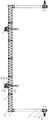
Fig. 1 is a schematic view of the structure of the present invention;
fig. 2 is a left side view structure diagram of the present invention;
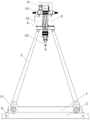
FIG. 3 is a schematic structural view of the anti-toppling device;
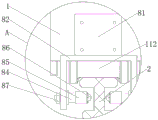
FIG. 4 is an enlarged view of portion A of FIG. 1;
FIG. 5 is a schematic diagram of the mechanism of the ball transfer unit.
Reference numerals: 1. a lower end beam; 2. an I-steel rail; 3. supporting legs; 4. an upper end beam; 5. a main beam; 6. a first lift truck; 7. a second trolley; 8. an anti-rollover device; 11. a cart traveling mechanism; 111. a cart traveling motor; 112. a cart travelling wheel; 51. a limiting block; 52. c, cable laying; 61. a trolley frame; 62. a hoisting mechanism; 63. a brake; 64. a trolley travelling mechanism; 65. lifting a lifting appliance; 81. a fixing plate; 82. a support frame; 83. an assembly hole; 84. a support shaft; 85. a rotating wheel; 86. a ball transfer unit; 861. mounting a plate; 862. a ball housing; 863. a ball bearing; 87. and (5) fixing the screw cap.
Detailed Description
As shown in fig. 1-5, a high-stability beam lifter comprises two parallel lower end beams 1 arranged at intervals, wherein the lower end beams 1 play a role in supporting and fixing, two end portions of each lower end beam 1 are respectively provided with a cart travelling mechanism 11, each cart travelling mechanism 11 is assembled with an i-shaped steel rail 2 laid on the ground, each cart travelling mechanism 11 comprises cart travelling wheels 112 assembled at two ends of each lower end beam 1, each cart travelling wheel 112 is in rolling fit with the i-shaped steel rail 2 below the corresponding lower end beam 1, a motor base is fixed on the outer side of each lower end beam 1, a cart travelling motor 111 is fixed on each motor base, and a power output shaft of each cart travelling motor 111 is in transmission connection with the cart travelling wheels 112 and can drive the whole beam lifter to freely move along the i-shaped steel rails 2 on the ground. The top ends of two lower end beams 1 are fixed with supporting legs 3, the supporting legs 3 are A-shaped and play a role in supporting and fixing, the top ends of the two supporting legs 3 are fixed with upper end beams 4 parallel to the lower end beams 1, two parallel main beams 5 arranged at intervals are arranged between the two upper end beams 4, two ends of the two main beams 5 are correspondingly fixed at the top ends of the upper end beams 1, I-shaped steel rails 2 are laid at the top ends of the two main beams 5, a first crane trolley 6 and a second crane trolley 7 are arranged above the main beams 5, the first crane trolley 6 and the second crane trolley 7 are both assembled on the I-shaped steel rails 2 at the top ends of the main beams 5, the first crane trolley 6 and the second crane trolley 7 are identical in structure and comprise trolley frames 61, lifting mechanisms 62, brakes 63 and trolley travelling mechanisms 64, each trolley travelling mechanism 64 comprises trolley travelling wheels assembled at two ends of each main beam 61, the travelling wheels are in rolling fit with the I-shaped steel rails 2 at the top ends of the main beams 5, a motor base is fixed on the outer side of the trolley frame 61, a trolley walking motor is fixed on the motor base, and a power output shaft of the trolley walking motor is in transmission connection with a trolley walking wheel. The hoisting mechanism 62 comprises a hoisting drum fixed at the top end of the trolley frame 61 and a hoisting motor, a power output shaft of the hoisting motor is in transmission connection with the hoisting drum through a speed reducer, a brake 63 is assembled with the power output shaft of the hoisting motor, a hoisting sling 65 is arranged right below the hoisting drum, and the hoisting sling 65 is connected with the hoisting drum through a steel wire rope. The two top ends of the lower end beam 1 are provided with the anti-dumping device 8, the anti-dumping device 8 comprises a fixing plate 81 which is vertically arranged, the fixing plate 81 can be detachably fixed at the top end of the lower end beam 1, the bottom end of the fixing plate 1 is fixedly provided with a support frame 82 which is in an inverted U shape, the lower end of the support frame 82 is arranged at the two sides of the I-steel rail 2, the support frames 82 at the two sides of the I-steel rail 2 are respectively provided with an assembly hole 83, the inner side of the support frame 82 is provided with two support shafts 84 which are horizontally and symmetrically arranged, one end of each support shaft 84 is fixed on each support frame 82 through the assembly hole 83, the other end of each support shaft 84 is provided with a rotating wheel 85 through a bearing, a gap exists between the upper wheel edge of each rotating wheel 85 and the upper end face of the I-steel rail 2, the rotating wheels 85 can freely rotate, the top ends of the rotating wheels 85 can be detachably fixed with universal balls 86, each universal ball 86 comprises a mounting plate 861, and through holes which are uniformly distributed are arranged on the mounting plate 861, the end of the rotating wheel 85 is provided with a threaded hole corresponding to the mounting plate 861, the mounting plate 861 is fixed at the end of the rotating wheel 85, the top end of the mounting plate 861 is fixed with a ball shell 862, balls 863 are assembled in the ball shell 862, and the rotating wheel 85 and the universal balls 86 are both positioned in grooves on two sides of the I-steel track 2.
Preferably, the assembly hole 83 is a vertically arranged bar-shaped through hole, the fixing end of the fixing shaft 84 is provided with a horizontally arranged threaded column, the threaded column extends out of the bar-shaped through hole, and the outer end of the threaded column is in threaded connection with a fixing nut 87.
Preferably, the main beam 5 is a triangular frame structure, the two end portions of the main beam 5 are respectively fixed with a limiting block 51 for limiting, the limiting blocks 51 block the first trolley 6 and the second trolley 7, the first trolley 6 and the second trolley 7 are prevented from being separated from the i-shaped steel track 2 during operation, and an expansion cable 52 is arranged on the outer side of one main beam 5.
Preferably, the cart traveling motor 111, the trolley traveling motor and the lifting motor are all communicated with a power supply through the extension cable 52, the cart traveling motor 111, the trolley traveling motor and the lifting motor are all connected with a PLC (programmable logic controller) of the lifting beam machine through the extension cable 52, and a worker can control the start and stop of the cart traveling motor 111, the trolley traveling motor and the lifting motor through a control system of the lifting beam machine by an operation platform.
The use process comprises the following steps:
the utility model discloses during the use, the staff starts cart walking motor 111 through the controller, under cart walking motor 111's drive, the bale lifter removes to wait to hang the building beam piece of getting directly over, only stop cart walking motor 111, start dolly walking motor respectively, adjust the position of first trolley 6 and second trolley 7, then it plays to rise the motor and puts down to play to rise hoist 65 to lead to the start, it lifts up building beam piece through playing to rise hoist 65, when waiting to build the beam piece and being lifted up, start cart walking motor 111, cart walking motor 111 drives the bale lifter and removes along subaerial I-steel track 2, in the moving process, when emergency braking appears, the upper wheel that rotates wheel 85 is along contacting and rolling with I-steel track 2, I-steel track 2 gives and rotates the decurrent power of wheel 85, avoided because of lower extreme roof beam 1 upwards removes, the derailment accident takes place. When the lifting beam machine moves, when the two supporting legs 3 are displaced and are asynchronous, rolling friction occurs between the ball 863 on the universal ball 85 and the I-shaped steel track, and the phenomenon that the cart travelling wheels 112 gnaw the track is avoided.
In the description of the present invention, it is to be understood that the terms "upper", "lower", "left", "right", "top", "bottom", "horizontal", "vertical", and the like indicate orientations or positional relationships based on the orientations or positional relationships shown in the drawings, and are used merely for convenience of description and simplification of description, and do not indicate or imply that the device or element being referred to must have a particular orientation, be constructed and operated in a particular orientation, and thus, should not be construed as limiting the present invention.
The above-mentioned embodiment is right the utility model discloses an explanation, it is not right the utility model discloses a limited, any right the scheme after the simple transform of the utility model all belongs to the protection scope of the utility model.
Claims (5)
1. The utility model provides a high-stability beam lifting machine, includes the lower end beam that two parallels and interval set up, and the both ends of lower end beam all are equipped with cart running gear, cart running gear with lay the assembly at subaerial I-steel track, two lower extreme roof beam tops all are fixed with the supporting leg, the top of two supporting legs all is fixed with the upper end beam parallel with the lower end beam, its characterized in that: two main beams which are parallel and arranged at intervals are arranged between the two upper end beams, two ends of each main beam are correspondingly fixed at the top ends of the upper end beams, I-shaped steel rails are laid at the top ends of the two main beams, a first crane trolley and a second crane trolley are arranged above the main beams, and the first crane trolley and the second crane trolley are assembled on the I-shaped steel rails; two tops of lower extreme roof beam are equipped with anti-overturning device, anti-overturning device includes the fixed plate of vertical setting, the top of fixing at the lower extreme roof beam can be dismantled to the fixed plate, the bottom mounting of fixed plate has the support frame that is the type of falling U, the lower extreme setting of support frame is in the orbital both sides of I-steel, the pilot hole has all been seted up on the support frame of I-steel track both sides, the inboard of support frame is equipped with the back shaft that two levels and symmetry set up, the one end of back shaft is passed through the pilot hole and is fixed on the support frame, the other end of back shaft is equipped with through the bearing and rotates the wheel, the top of rotating the wheel can be dismantled and is fixed with universal ball, it all lies in the recess on I-steel track both sides to rotate wheel and universal ball.
2. The high-stability beam lifting machine according to claim 1, characterized in that: the pilot hole is the bar through-hole of vertical setting, and the stiff end of fixed axle is equipped with the screw thread post that the level set up, and the bar through-hole is extended to the screw thread post, and the outer end threaded connection of screw thread post has fixation nut.
3. The high-stability beam lifting machine as claimed in claim 2, wherein: the universal ball comprises a mounting plate, through holes which are uniformly distributed are formed in the mounting plate, threaded holes are formed in the end portion of the rotating wheel corresponding to the mounting plate, the mounting plate is fixed at the end portion of the rotating wheel, a ball shell is fixed at the top end of the mounting plate, and balls are assembled in the ball shell.
4. The high-stability beam lifting machine according to claim 1, characterized in that: the cart travelling mechanism comprises cart travelling wheels assembled at two ends of the lower end beam, the cart travelling wheels are in rolling fit with the I-steel rails below the lower end beam, a motor base is fixed on the outer side of the lower end beam, a cart travelling motor is fixed on the motor base, and a power output shaft of the cart travelling motor is in transmission connection with the cart travelling wheels.
5. The high-stability beam lifting machine according to claim 1, characterized in that: the first lifting trolley and the second lifting trolley are identical in structure and comprise trolley frames, lifting mechanisms, brakes and trolley travelling mechanisms, each trolley travelling mechanism comprises trolley travelling wheels assembled at two ends of each trolley frame, the trolley travelling wheels are in rolling fit with I-steel rails at the top ends of the main beams, motor bases are fixed on the outer sides of the trolley frames, trolley travelling motors are fixed on the motor bases, and power output shafts of the trolley travelling motors are in transmission connection with the trolley travelling wheels; the lifting mechanism comprises a lifting reel and a lifting motor which are fixed at the top end of the trolley frame, a power output shaft of the lifting motor is in transmission connection with the lifting reel through a speed reducer, a brake is assembled with the power output shaft of the lifting motor, a lifting sling is arranged under the lifting reel, and the lifting sling is connected with the lifting reel through a steel wire rope.
Priority Applications (1)
| Application Number | Priority Date | Filing Date | Title |
|---|---|---|---|
| CN202120071444.XU CN214570227U (en) | 2021-01-12 | 2021-01-12 | High-stability beam lifting machine |
Applications Claiming Priority (1)
| Application Number | Priority Date | Filing Date | Title |
|---|---|---|---|
| CN202120071444.XU CN214570227U (en) | 2021-01-12 | 2021-01-12 | High-stability beam lifting machine |
Publications (1)
| Publication Number | Publication Date |
|---|---|
| CN214570227U true CN214570227U (en) | 2021-11-02 |
Family
ID=78368283
Family Applications (1)
| Application Number | Title | Priority Date | Filing Date |
|---|---|---|---|
| CN202120071444.XU Active CN214570227U (en) | 2021-01-12 | 2021-01-12 | High-stability beam lifting machine |
Country Status (1)
| Country | Link |
|---|---|
| CN (1) | CN214570227U (en) |
-
2021
- 2021-01-12 CN CN202120071444.XU patent/CN214570227U/en active Active
Similar Documents
| Publication | Publication Date | Title |
|---|---|---|
| CN212050244U (en) | Gantry crane system for mounting assembled bent cap | |
| CN113202020A (en) | Arch rib maintenance vehicle suitable for box type arch rib inspection | |
| CN111502293B (en) | Method and system for hoisting single peripheral component of assembly type building | |
| CN211034929U (en) | Double-beam bridge crane | |
| CN100417586C (en) | Integral lifting method of large bridge crane and its appts | |
| CN214653067U (en) | Upper rotating crane trolley of crane special for steel plant | |
| CN213085256U (en) | Single-beam portal crane with suspended trolley | |
| CN214570227U (en) | High-stability beam lifting machine | |
| CN214570231U (en) | High-stability beam lifting machine | |
| CN216038231U (en) | General gantry crane | |
| CN212740481U (en) | Tire gantry crane | |
| CN215854729U (en) | Gantry crane for high-speed rail | |
| CN212387581U (en) | Safe supporting device for disassembling crane | |
| CN212559149U (en) | Prevent gnawing rail anticreep rail monkey | |
| CN101734558A (en) | Metallurgy hopper bridge crane | |
| CN211255000U (en) | Single-girder gantry crane | |
| CN207877136U (en) | A kind of wheel-track type bale handle carrying implement | |
| CN214399568U (en) | Novel beam lifting machine | |
| CN218708558U (en) | Device for hoisting reinforcement cage in cantilever casting segment construction | |
| CN111470431A (en) | Large-tonnage pipe ring hoisting machine | |
| CN212769511U (en) | LDP dolly of restricting down in two-sided | |
| CN201660377U (en) | Special gantry crane for overlength and large-tonnage parts | |
| CN213475222U (en) | Beam lifting machine with stepless span changing device | |
| CN214141300U (en) | Special double-beam bridge crane for metallurgy | |
| CN212475828U (en) | Spliced type lifting beam portal crane |
Legal Events
| Date | Code | Title | Description |
|---|---|---|---|
| GR01 | Patent grant | ||
| GR01 | Patent grant |