CN214521144U - Stone cutting mechanical equipment - Google Patents
Stone cutting mechanical equipment Download PDFInfo
- Publication number
- CN214521144U CN214521144U CN202120022233.7U CN202120022233U CN214521144U CN 214521144 U CN214521144 U CN 214521144U CN 202120022233 U CN202120022233 U CN 202120022233U CN 214521144 U CN214521144 U CN 214521144U
- Authority
- CN
- China
- Prior art keywords
- cutting
- frame
- stone
- moving
- sliding table
- Prior art date
- Legal status (The legal status is an assumption and is not a legal conclusion. Google has not performed a legal analysis and makes no representation as to the accuracy of the status listed.)
- Active
Links
Images


Landscapes
- Processing Of Stones Or Stones Resemblance Materials (AREA)
Abstract
The utility model discloses a stone material cutting mechanical equipment belongs to stone material processing technology field, including cutting frame, mobile device, rotary device, first cutting device, thrust unit, brace table, support frame and second cutting device, the mobile device sets up on the cutting frame, rotary device installs on the mobile device, first cutting device installs on rotary device, thrust unit sets up the both sides at the cutting frame, the brace table sets up the side at the cutting frame, the support frame welding is on the brace table, second cutting device installs on the support frame, the utility model provides a stone material cutting mechanical equipment can carry out sharp and curvilinear cutting to the stone material, improve device's practicality.
Description
Technical Field
The utility model relates to a stone material processing technology field especially relates to a stone material cutting machine equipment.
Background
The stone material is mostly as the outside bearing structure material of building, be applied to on the large-scale engineering, along with the development of times, novel concrete and steel structure replace the peripheral bearing material of stone material building gradually, the stone material evolves into a high-grade architectural decoration material gradually, the wide application is in indoor outer decoration design, but the stone material is all more crude before the use, or the shape is not conform to the requirement, these stones can only reach final result of use through the artifical cutting of polishing or mechanical cutting, the manual working stone material is because inefficiency, polish inhomogeneous and the operation difficulty, therefore, the manual working stone material is replaced by machining gradually.
The utility model discloses a stone cutting machine of the prior publication No. CN210025847U, the utility model provides a stone cutting machine, which comprises a frame, a stone conveying device and a stone cutting device, wherein the stone cutting device comprises a saw blade, a cutting motor and a saw blade headstock, the saw blade headstock comprises a box body and a main shaft, the main shaft is rotatably arranged in the box body in a penetrating way, one end of the main shaft is provided with a saw blade connecting part, the other end of the main shaft is in transmission connection with a rotating shaft of the cutting motor, a first waterproof structure is arranged between the main shaft and the box body, the cutting motor is provided with a shell, the box body is detachably fixed on the shell body, a box body sealing cover is arranged at the part of the rotating shaft exposed out of the shell body, a second waterproof structure is arranged at the contact position of the box body and the shell body, the stone conveying device comprises a first conveying belt device and a second conveying belt device which are arranged with mutually vertical conveying surfaces, the first conveying belt device and the second conveying belt device are arranged in synchronous transmission, the utility model has the advantages of as follows: the waterproof performance is better, the saw bit job stabilization is difficult for disconnected axle and conveyer reliability is higher.
Above-mentioned utility model can only carry out the straight line cutting to the stone material, can't cut into curved structure with the stone material, when cutting different stone materials, the rate of adaptation is not high, only utilizes cutting device to cut through removing the stone material simultaneously, and cutting efficiency is relatively poor.
SUMMERY OF THE UTILITY MODEL
An embodiment of the utility model provides a stone material cutting mechanical equipment to solve above-mentioned technical problem.
The embodiment of the utility model provides an adopt following technical scheme: the utility model provides a stone material cutting mechanical equipment, includes cutting frame, mobile device, rotary device, first cutting device, thrust unit, brace table, support frame and second cutting device, the mobile device sets up on the cutting frame, rotary device installs on the mobile device, first cutting device installs on rotary device, thrust unit sets up the both sides at the cutting frame, the brace table sets up the side at the cutting frame, the support frame welding is on the brace table, second cutting device installs on the support frame.
Further, the mobile device includes first lead screw slip table, second lead screw slip table, removes the frid, removes telescopic link and movable plate, first lead screw slip table is installed on the cutting frame, second lead screw slip table is installed on the cutting frame, it installs on the slip table of first lead screw slip table to remove the frid, movable plate slidable mounting is in removing the frid, the one end of removing the telescopic link is installed on the slip table of second lead screw slip table and the other end is connected on the movable plate.
Further, rotary device includes rotating electrical machines, worm wheel and worm, the worm rotates and installs on the movable plate, rotating electrical machines installs on the movable plate and rotating electrical machines's main shaft is connected on the worm, the worm wheel rotates and installs on the movable plate and mesh mutually with the worm.
Further, first cutting device includes flexible electric jar, bears box, first cutting motor and cutting disc, flexible electric jar is installed on the worm wheel, it installs on the flexible end of flexible electric jar to bear the box, first cutting motor sets up in bearing the box, the cutting disc rotates to be installed on the main shaft of first cutting motor.
Further, the pushing device comprises two pushing screw rod sliding tables and two pushing frames, the two pushing frames are symmetrically arranged on two sides of the cutting frame respectively, and one ends of the pushing frames are installed on the sliding tables of the pushing screw rod sliding tables.
Further, the second cutting device comprises a cutting rack, two cutting assemblies and two cutting screw sliding tables, the two cutting screw sliding tables are respectively arranged on the horizontal plane and the supporting frame, the two cutting assemblies are respectively and symmetrically arranged on the sliding tables of the two cutting screw sliding tables, the two cutting assemblies respectively comprise a connecting frame, a second cutting motor, a rotating disc, a rotating rod, a supporting plate and a rotating wheel, the connecting frame is arranged on the sliding of the cutting screw rod sliding table, the second cutting motor is arranged on the connecting frame, the rotating disc is arranged on a main shaft of the second cutting motor, one end of the rotating rod is hinged on the rotating disc, the backup pad welding is on the link, it installs in the backup pad to rotate the wheel, the cutting rack cover is established and is rotated on two wheels and both ends and articulate the other end at two dwang respectively.
The embodiment of the utility model provides an above-mentioned at least one technical scheme who adopts can reach following beneficial effect:
firstly, the moving device in the utility model drives the moving plate to move on the plane by the first screw rod sliding table and the second screw rod sliding table through the moving groove plate and the moving telescopic rod, and drives the rotating device and the first cutting device to move, so that the first cutting device cuts the stone; when the stone material got into on the cutting frame, first lead screw slip table drive drove and removes the frid and remove, thereby drive the movable plate extrusion and remove the telescopic link and stretch out and draw back and remove along with first lead screw slip table, second lead screw slip table drive removes the telescopic link and removes, drives the movable plate and removes in removing the frid, conveniently cuts the stone material.
Secondly, the worm wheel is driven by the rotating motor to rotate to drive the first cutting device to rotate, so that multi-angle cutting can be performed, and the cutting practicability of the device is improved; when the angle of the first cutting device needs to be changed during cutting, the rotating motor operates to drive the worm to rotate, and then the worm is driven to rotate, so that the angle of the first cutting device is adjusted.
Thirdly, the second cutting device drives the cutting rack to reciprocate at high speed on the two rotating wheels by the two second cutting motors to cut the stone pushed by the pushing frame, and then drives the two cutting assemblies to move by the two cutting screw rod sliding tables to be matched with the pushing frame to cut the curve of the stone; when the pushing frame promotes the stone material and gets into cutting rack department, two high-speed operations of second cutting motor drive two angles and differ the rolling disc rotation of half week, thereby drive the dwang and remove, two dwangs are under the rotation of the rolling disc that two angles differ the half week, drive the cutting rack and take turns to two and carry out high-speed reciprocating motion, two cutting lead screw slip tables operation simultaneously, drive two cutting assembly and remove, under the promotion of pushing frame, the stone material continues to move, thereby make the cutting rack carry out the curve cutting to the stone material.
Drawings
The accompanying drawings, which are described herein, serve to provide a further understanding of the invention and constitute a part of this specification, and the exemplary embodiments and descriptions thereof are provided for explaining the invention without unduly limiting it. In the drawings:
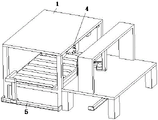
fig. 1 is a schematic perspective view of the present invention;
fig. 2 is a schematic perspective view of the present invention;
fig. 3 is a schematic perspective view of the mobile device of the present invention;
fig. 4 is a schematic view of a partial three-dimensional structure of the present invention;
fig. 5 is a schematic perspective view of the rotating device of the present invention;
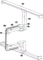
fig. 6 is a schematic perspective view of a second cutting device according to the present invention.
Reference numerals
The cutting frame 1, the moving device 2, the rotating device 3, the first cutting device 4, the pushing device 5, the supporting table 11, the supporting frame 12, the second cutting device 6, the first screw rod sliding table 21, the second screw rod sliding table 22, the moving groove plate 23, the moving telescopic rod 24, the moving plate 25, the rotating motor 31, the worm gear 32, the worm 33, the telescopic electric cylinder 41, the bearing box 42, the first cutting motor 43, the cutting disc 44, the pushing screw rod sliding table 51, the pushing frame 52, the cutting rack 61, the cutting assembly 62, the cutting screw rod sliding table 63, the connecting frame 64, the second cutting motor 65, the rotating disc 66, the rotating rod 67, the supporting plate 68 and the rotating wheel 69.
Detailed Description
To make the purpose, technical solution and advantages of the present invention clearer, the following will combine the embodiments of the present invention and the corresponding drawings to clearly and completely describe the technical solution of the present invention. It is to be understood that the embodiments described are only some embodiments of the invention, and not all embodiments. Based on the embodiments in the present invention, all other embodiments obtained by a person skilled in the art without creative work belong to the protection scope of the present invention.
The technical solutions provided by the embodiments of the present invention are described in detail below with reference to the accompanying drawings.
Referring to fig. 1 to 6, an embodiment of the present invention provides a stone cutting machine, including cutting frame 1, mobile device 2, rotary device 3, first cutting device 4, thrust unit 5, supporting bench 11, support frame 12 and second cutting device 6, mobile device 2 sets up on cutting frame 1, rotary device 3 installs on mobile device 2, first cutting device 4 installs on rotary device 3, thrust unit 5 sets up the both sides at cutting frame 1, supporting bench 11 sets up the side at cutting frame 1, support frame 12 welds on supporting bench 11, second cutting device 6 installs on support frame 12.
Preferably, referring to fig. 3, the moving device 2 includes a first screw rod sliding table 21, a second screw rod sliding table 22, a moving groove plate 23, a moving telescopic rod 24 and a moving plate 25, the first screw rod sliding table 21 is installed on the cutting frame 1, the second screw rod sliding table 22 is installed on the cutting frame 1, the moving groove plate 23 is installed on the sliding table of the first screw rod sliding table 21, the moving plate 25 is installed in the moving groove plate 23 in a sliding manner, one end of the moving telescopic rod 24 is installed on the sliding table of the second screw rod sliding table 22, and the other end is connected to the moving plate 25; the moving device 2 drives the moving plate 25 to move on the plane through the moving groove plate 23 and the moving telescopic rod 24 by the first screw rod sliding table 21 and the second screw rod sliding table 22, and drives the rotating device 3 and the first cutting device 4 to move, so that the first cutting device 4 cuts the stone; when the stone material gets into on the cutting frame 1, first lead screw slip table 21 drive drives and removes frid 23 removal, thereby drives movable plate 25 extrusion removal telescopic link 24 and stretch out and draw back and remove along with first lead screw slip table 21, and second lead screw slip table 22 drive removes telescopic link 24 and removes, drives movable plate 25 and removes in removing frid 23, conveniently cuts the stone material.
Preferably, referring to fig. 5, the rotating device 3 includes a rotating motor 31, a worm wheel 32 and a worm 33, the worm 33 is rotatably mounted on the moving plate 25, the rotating motor 31 is mounted on the moving plate 25, a main shaft of the rotating motor 31 is connected to the worm 33, and the worm wheel 32 is rotatably mounted on the moving plate 25 and engaged with the worm 33; the rotating device 3 drives the worm wheel 32 to rotate by the rotating motor 31, and drives the first cutting device 4 to rotate, so that multi-angle cutting can be realized, and the cutting practicability of the device is improved; when the cutting requires changing the angle of the first cutting device 4, the rotating motor 31 is operated to rotate the worm 33, and then the worm 33 is rotated, thereby adjusting the angle of the first cutting device 4.
Preferably, referring to fig. 4, the first cutting device 4 comprises a telescopic electric cylinder 41, a carrying box 42, a first cutting motor 43 and a cutting disc 44, wherein the telescopic electric cylinder 41 is mounted on the worm gear 32, the carrying box 42 is mounted on the telescopic end of the telescopic electric cylinder 41, the first cutting motor 43 is arranged in the carrying box 42, and the cutting disc 44 is rotatably mounted on the main shaft of the first cutting motor 43; the first cutting device 4 drives the cutting disc 44 to reach the surface of the stone material by the telescopic electric cylinder 41, and then the first cutting motor 43 drives the cutting disc 44 to cut the stone material, so that the cutting can be more effectively carried out under the cooperation of the rotating device 3 and the moving device 2.
Preferably, referring to fig. 2, the pushing device 5 includes two pushing screw sliding tables 51 and two pushing frames 52, the two pushing frames 52 are respectively symmetrically arranged at two sides of the cutting frame 1, and one end of each of the two pushing frames 52 is mounted on the sliding table of the pushing screw sliding table 51; the pushing device 5 is formed by driving two pushing frames 52 to push the stone to move to the second cutting device 6 by two pushing screw rod sliding tables 51, so that the stone is cut in a curve, and time and labor are saved; when the stone needs to be curved and polished, the two pushing screw sliding tables 51 drive the two pushing frames 52 to push the stone to move, and the stone is matched with the second cutting device 6 to be curved and polished.
Preferably, referring to fig. 6, the second cutting device 6 includes a cutting rack 61, two cutting assemblies 62 and two cutting screw sliding tables 63, two cutting screw sliding tables 63 are respectively installed on the horizontal plane and the support frame 12, two cutting assemblies 62 are respectively symmetrically disposed on the sliding tables of the two cutting screw sliding tables 63, two cutting assemblies 62 respectively include a connecting frame 64, a second cutting motor 65, a rotating disc 66, a rotating rod 67, a support plate 68 and a rotating wheel 69, the connecting frame 64 is installed on the sliding of the cutting screw sliding tables 63, the second cutting motor 65 is installed on the connecting frame 64, the rotating disc 66 is installed on the main shaft of the second cutting motor 65, one end of the rotating rod 67 is hinged on the rotating disc 66, the support plate 68 is welded on the connecting frame 64, the rotating wheel 69 is rotatably installed on the support plate 68, the cutting rack 61 is sleeved on the two rotating wheels 69, and two ends of the cutting rack are respectively hinged to the other ends of the two rotating rods 67; the second cutting device 6 is characterized in that two second cutting motors 65 drive the cutting racks 61 to reciprocate at high speed on two rotating wheels 69 to cut the stone pushed by the pushing frame 52, and then two cutting screw sliding tables 63 drive two cutting assemblies 62 to move to match with the pushing frame 52 to cut the stone in a curve; when pushing away frame 52 and promoting the stone material and get into cutting rack 61 department, two second cutting motor 65 high-speed operation, it rotates to drive two angles and differ the rolling disc 66 of half week, thereby drive rolling disc 67 and remove, two rolling disc 67 are under the rotation of two angles and differ the rolling disc 66 of half week, drive high-speed reciprocating motion on two rolling wheel 69 of cutting rack 61, two cutting lead screw slip tables 63 operate simultaneously, drive two cutting assembly 62 and remove, under the promotion of pushing away frame 52, the stone material continues to move, thereby make cutting rack 61 carry out the curve cutting to the stone material.
The utility model discloses a theory of operation: the moving device 2 drives the moving plate 25 to move on the plane through the moving groove plate 23 and the moving telescopic rod 24 by the first screw rod sliding table 21 and the second screw rod sliding table 22, and drives the rotating device 3 and the first cutting device 4 to move, so that the first cutting device 4 cuts the stone; when the stone enters the cutting frame 1, the first screw rod sliding table 21 drives the movable groove plate 23 to move, the movable plate 25 is driven to extrude the movable telescopic rod 24 to stretch and move so as to move along with the first screw rod sliding table 21, the second screw rod sliding table 22 drives the movable telescopic rod 24 to move, the movable plate 25 is driven to move in the movable groove plate 23, the stone is conveniently cut, the rotating device 3 drives the worm gear 32 to rotate through the rotating motor 31, the first cutting device 4 is driven to rotate, multi-angle cutting can be achieved, and the cutting practicability of the device is improved; when the angle of the first cutting device 4 needs to be changed during cutting, the rotating motor 31 operates to drive the worm 33 to rotate, and then the worm 33 is driven to rotate, so that the angle of the first cutting device 4 is adjusted, the first cutting device 4 drives the cutting disc 44 to reach the surface of the stone by the telescopic electric cylinder 41, then the first cutting motor 43 drives the cutting disc 44 to cut the stone, and under the cooperation of the rotating device 3 and the moving device 2, the stone can be cut more effectively, the pushing device 5 drives the two pushing frames 52 to push the stone to move to the second cutting device 6 by the two pushing screw rod sliding tables 51, so that the stone is cut in a curve manner, and time and labor are saved; when the stone material need carry out the curve and polish, two promote lead screw slip tables 51 and drive two promotion framves 52 and promote the stone material and remove, cooperation second cutting device 6 carries out the curve and polishes, when promotion frame 52 promotes the stone material and gets into cutting rack 61 department, two second cutting motor 65 high-speed operation, it rotates to drive two angles and differs the rolling disc 66 of half week, thereby it removes to drive dwang 67, two dwang 67 are under the rotation of two angles and differ the rolling disc 66 of half week, drive high-speed reciprocating motion on two rolling wheels 69 of cutting rack 61, two cutting lead screw slip tables 63 operate simultaneously, drive two cutting assembly 62 and remove, under the promotion of promotion frame 52, the stone material continues to move, thereby make cutting rack 61 carry out the curve cutting to the stone material.
The above description is only an example of the present invention, and is not intended to limit the present invention. Various modifications and changes may occur to those skilled in the art. Any modification, equivalent replacement, or improvement made within the spirit and principle of the present invention should be included in the scope of the claims of the present invention.
Claims (6)
1. The utility model provides a stone material cutting mechanical equipment, its characterized in that, includes cutting frame (1), mobile device (2), rotary device (3), first cutting device (4), thrust unit (5), brace table (11), support frame (12) and second cutting device (6), mobile device (2) set up on cutting frame (1), rotary device (3) are installed on mobile device (2), install on rotary device (3) first cutting device (4), thrust unit (5) set up the both sides at cutting frame (1), brace table (11) set up the side at cutting frame (1), support frame (12) welding is on brace table (11), second cutting device (6) are installed on support frame (12).
2. The stone cutting machine according to claim 1, wherein the moving device (2) comprises a first screw rod sliding table (21), a second screw rod sliding table (22), a moving groove plate (23), a moving telescopic rod (24) and a moving plate (25), the first screw rod sliding table (21) is installed on the cutting frame (1), the second screw rod sliding table (22) is installed on the cutting frame (1), the moving groove plate (23) is installed on the sliding table of the first screw rod sliding table (21), the moving plate (25) is slidably installed in the moving groove plate (23), one end of the moving telescopic rod (24) is installed on the sliding table of the second screw rod sliding table (22), and the other end of the moving telescopic rod is connected to the moving plate (25).
3. The stone cutting machine as claimed in claim 2, characterized in that said rotation means (3) comprise a rotation motor (31), a worm wheel (32) and a worm (33), said worm (33) being rotatably mounted on the moving plate (25), said rotation motor (31) being mounted on the moving plate (25) and the main shaft of the rotation motor (31) being connected to the worm (33), said worm wheel (32) being rotatably mounted on the moving plate (25) and meshing with the worm (33).
4. A stone cutting machine as claimed in claim 3, characterized in that said first cutting means (4) comprise an electric telescopic cylinder (41), a carrying box (42), a first cutting motor (43) and a cutting disc (44), said electric telescopic cylinder (41) being mounted on the worm gear (32), said carrying box (42) being mounted on the telescopic end of the electric telescopic cylinder (41), said first cutting motor (43) being arranged inside the carrying box (42), said cutting disc (44) being rotatably mounted on the main shaft of the first cutting motor (43).
5. The stone cutting machine as claimed in claim 1, wherein said pushing device (5) comprises two pushing screw sliding tables (51) and two pushing frames (52), said two pushing frames (52) are respectively symmetrically disposed at two sides of the cutting frame (1), one end of said two pushing frames (52) is mounted on the sliding table of the pushing screw sliding table (51).
6. The stone cutting machine as claimed in claim 1, wherein the second cutting device (6) comprises a cutting rack (61), two cutting assemblies (62) and two cutting screw sliding tables (63), the two cutting screw sliding tables (63) are respectively installed on the horizontal plane and the support frame (12), the two cutting assemblies (62) are respectively and symmetrically arranged on the sliding tables of the two cutting screw sliding tables (63), the two cutting assemblies (62) respectively comprise a connecting frame (64), a second cutting motor (65), a rotating disc (66), a rotating rod (67), a support plate (68) and a rotating wheel (69), the connecting frame (64) is installed on the sliding of the cutting screw sliding tables (63), the second cutting motor (65) is installed on the connecting frame (64), and the rotating disc (66) is installed on the main shaft of the second cutting motor (65), one end of dwang (67) articulates on rolling disc (66), backup pad (68) welding is on link (64), it installs on backup pad (68) to rotate wheel (69), cutting rack (61) cover is established on two rotation wheels (69) and both ends articulate the other end at two dwang (67) respectively.
Priority Applications (1)
| Application Number | Priority Date | Filing Date | Title |
|---|---|---|---|
| CN202120022233.7U CN214521144U (en) | 2021-01-06 | 2021-01-06 | Stone cutting mechanical equipment |
Applications Claiming Priority (1)
| Application Number | Priority Date | Filing Date | Title |
|---|---|---|---|
| CN202120022233.7U CN214521144U (en) | 2021-01-06 | 2021-01-06 | Stone cutting mechanical equipment |
Publications (1)
| Publication Number | Publication Date |
|---|---|
| CN214521144U true CN214521144U (en) | 2021-10-29 |
Family
ID=78300963
Family Applications (1)
| Application Number | Title | Priority Date | Filing Date |
|---|---|---|---|
| CN202120022233.7U Active CN214521144U (en) | 2021-01-06 | 2021-01-06 | Stone cutting mechanical equipment |
Country Status (1)
| Country | Link |
|---|---|
| CN (1) | CN214521144U (en) |
-
2021
- 2021-01-06 CN CN202120022233.7U patent/CN214521144U/en active Active
Similar Documents
| Publication | Publication Date | Title |
|---|---|---|
| CN107127666A (en) | A kind of Digit Control Machine Tool machined burrs removal device | |
| CN209920264U (en) | Track rotary cutting machine for cutting concrete | |
| CN210189311U (en) | Corner grinding device convenient for plastic product replacement | |
| CN112659388A (en) | Deburring device for gypsum brick production | |
| CN113021120A (en) | System and method for processing curved surface of object surface | |
| CN108673754A (en) | A kind of makita 4100NH convenient for lubricated blades | |
| CN111644914A (en) | Pipe cutting grinding device for machine-building | |
| CN114211034A (en) | Shaping and cleaning workpiece surface integrated shaping machine auxiliary device | |
| CN214521144U (en) | Stone cutting mechanical equipment | |
| CN202964921U (en) | Stone cutting work table | |
| CN216831648U (en) | Chamfering type optical glass cutting device | |
| CN114800766A (en) | Edge banding machine for wood working machinery | |
| CN212496923U (en) | Automatic notch burr removing machine for steel pipe | |
| CN208529432U (en) | A kind of makita 4100NH convenient for lubricated blades | |
| CN209902928U (en) | Novel flexible polishing equipment | |
| CN113118776A (en) | Special processingequipment of electric tool gear | |
| CN105382540A (en) | Edging pipe cutting machine | |
| CN216228369U (en) | Equipment for grinding outer circle of hard alloy rod | |
| CN217832036U (en) | Cutting tool head adjusting device for milling machine | |
| CN220330859U (en) | Precious stone level single crystal diamond seed crystal corner grinding device | |
| CN217702707U (en) | Deburring device for machining of running machine | |
| CN213702736U (en) | Grinding machine of making an uproar falls | |
| CN216503876U (en) | Surface grinding equipment for bearing preparation | |
| CN221675949U (en) | Rotary cutting device for product protection sleeve | |
| CN216298870U (en) | Grinding device convenient for workpiece reversal for metal part machining |
Legal Events
| Date | Code | Title | Description |
|---|---|---|---|
| GR01 | Patent grant | ||
| GR01 | Patent grant |