CN214456361U - Wall head crane with rotatable suspension arm - Google Patents
Wall head crane with rotatable suspension arm Download PDFInfo
- Publication number
- CN214456361U CN214456361U CN202023040065.9U CN202023040065U CN214456361U CN 214456361 U CN214456361 U CN 214456361U CN 202023040065 U CN202023040065 U CN 202023040065U CN 214456361 U CN214456361 U CN 214456361U
- Authority
- CN
- China
- Prior art keywords
- rods
- clamping
- wall
- scissor
- wall body
- Prior art date
- Legal status (The legal status is an assumption and is not a legal conclusion. Google has not performed a legal analysis and makes no representation as to the accuracy of the status listed.)
- Active
Links
- 239000000725 suspension Substances 0.000 title claims abstract description 25
- 238000004873 anchoring Methods 0.000 claims abstract description 4
- 229910000831 Steel Inorganic materials 0.000 claims description 8
- 239000010959 steel Substances 0.000 claims description 8
- 230000000149 penetrating effect Effects 0.000 claims description 3
- 230000003014 reinforcing effect Effects 0.000 claims description 3
- 238000000034 method Methods 0.000 abstract description 4
- 238000010276 construction Methods 0.000 description 2
- 230000000694 effects Effects 0.000 description 2
- 238000009434 installation Methods 0.000 description 2
- 230000009286 beneficial effect Effects 0.000 description 1
- 239000004566 building material Substances 0.000 description 1
- 238000012986 modification Methods 0.000 description 1
- 230000004048 modification Effects 0.000 description 1
- 239000003351 stiffener Substances 0.000 description 1
Images
Landscapes
- Jib Cranes (AREA)
Abstract
The utility model relates to a winch, in particular to a wall crane with a rotatable suspension arm, which comprises a suspension arm, an electric hoist arranged on the suspension arm and a fixing device used for anchoring the suspension arm at the top of a wall body, wherein the fixing device comprises two scissor rods which are crossed at the middle parts and are hinged into a scissor shape through a vertical main shaft, and two ends of each scissor rod are respectively provided with a clamping rod used for clamping the wall body; two clamping rods on the same scissor rod are respectively arranged on two sides of the wall body, and each clamping rod is connected with the clamping rods which are positioned on the opposite side of the wall body and belong to different scissor rods through opposite-pulling screw rods; the suspension arm is rotatably connected with the main shaft. In the utility model, the scissor bar and the clamping bar are combined into a clamping type fixing device, and the clamping device is clamped at the wall head after the tension screw is tightened, has no special requirements on the wall structure and can be used for clamping various walls; meanwhile, a main shaft connected with the scissor bar is used as a pin shaft of the suspension arm, so that the suspension arm can rotate, and adjustment in the hoisting process is facilitated.
Description
Technical Field
The utility model relates to a hoist engine especially relates to a rotatable wall of davit hangs.
Background
In low-rise buildings, building materials are mainly hoisted by means of a crane, the crane is of a vehicle-mounted type and is hoisted on the ground, and the crane is also of a fixed type and is hoisted on a roof.
However, during the construction of municipal engineering buildings, the crane often cannot approach the periphery of the building due to underground structures, obstacles and the like, for example, the crane exists in a building crack with high and low spans or a bottom layer of a high-rise building with steps. At this time, some cranes which have simple structures and can be disassembled and transported to a use position for assembly are needed. For example, a crane is often assembled on the roof for hoisting a building wall facing.
However, the parapet wall around the roof is often built earlier than the roof itself, and in order to shorten the construction period, the installation of the decorative boards on the wall surface is often not performed until the building of the roof is completed, and in this case, a crane is required to be fixed to the head of the parapet wall for hoisting, and the crane is generally called a head crane.
The existing wall head crane is often narrow in application range, and generally depends on a specific structure on a certain specific parapet wall to realize fixation, such as a steel pipe on the parapet wall with double rows of railing type. In addition, the wall head crane is limited by narrow installation scenes, almost all the suspension arms of the wall head crane cannot rotate, and a part to be hoisted can only move up and down in the using process.
SUMMERY OF THE UTILITY MODEL
The utility model provides a rotatable wall head of davit hangs.
The technical problem to be solved is that: the existing wall head crane has poor universality, and the suspension arm of the existing wall head crane cannot rotate frequently.
In order to solve the technical problem, the utility model adopts the following technical scheme:
a wall crane with a rotatable suspension arm comprises the suspension arm, an electric hoist arranged on the suspension arm and a fixing device for anchoring the suspension arm at the top of a wall body, wherein the fixing device comprises two scissor rods, the middle parts of the scissor rods are crossed and hinged into a scissor shape, the two scissor rods are higher than the top of the wall body and are horizontally arranged, and two ends of each scissor rod are respectively provided with a clamping rod for clamping the wall body; the clamping rods are vertically arranged, the upper ends of the clamping rods are fixedly connected with the end parts of the scissor rods, the side surfaces of the clamping rods are arranged by being attached to the wall surface of the wall body, and the two clamping rods on the same scissor rod are respectively arranged on two sides of the wall body;
each clamping rod is connected with a clamping rod which is positioned at the opposite side of the wall body and belongs to different shear rod rods through a counter-pulling screw rod, and the counter-pulling screw rod is higher than the top of the wall body and horizontally penetrates through the two clamping rods;
the two scissor rods are rotatably connected by taking a main shaft which vertically penetrates through the two scissor rods upwards and then extends upwards as a pin shaft, and one end of the suspension arm is rotatably connected with the main shaft by taking the main shaft as a rotating shaft.
Furthermore, the clamping rod is a threaded rod, and threads of the threaded rod are trapezoidal threads.
Furthermore, the clamping rod is a square steel pipe, and one side surface of the square steel pipe is arranged by being attached to the wall surface of the wall body.
Further, the upper end of the main shaft is sleeved with a sleeve, the upper end of the sleeve is sealed, and one end of the suspension arm is anchored on the side face of the sleeve and is rotatably connected with the main shaft through the sleeve.
Further, the davit is truss structure, including two truss mobile jib and set up between two truss mobile jib and respectively with two truss mobile jib fixed connection's stiffener, two truss mobile jib one end coincidence and interconnect, the other end staggers from top to bottom the back and is connected with the sleeve side respectively.
Furthermore, the motor of the electric hoist is clamped between the two truss main rods and is fixedly connected with the two truss main rods respectively.
Further, the split screw rod is in clearance fit with the clamping rod penetrating through the split screw rod.
The utility model relates to a rotatable wall of davit hangs compares with prior art, has following beneficial effect:
in the utility model, the scissor bar and the clamping bar are combined into a clamping type fixing device, and the clamping device is clamped at the wall head after the tension screw is tightened, has no special requirements on the wall structure and can be used for clamping various walls; meanwhile, a main shaft connected with the scissor bar is used as a pin shaft of the suspension arm, so that the suspension arm can rotate, and adjustment in the hoisting process is facilitated.
Drawings
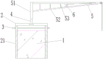
Fig. 1 is a front view of a wall head crane with a rotatable boom of the present invention;
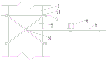
fig. 2 is a top view of a wall head crane with a rotatable boom of the present invention;
the device comprises a wall body 1, a shear bar 2, a clamping bar 21, a tension screw 3, a main shaft 4, a suspension arm 5, a sleeve 51, a truss main rod 52, a reinforcing rod 53 and a motor 6.
Detailed Description
As shown in fig. 1-2, a wall crane with a rotatable boom comprises a boom 5, an electric hoist arranged on the boom 5, and a fixing device for anchoring the boom 5 to the top of a wall 1, wherein the fixing device comprises two scissor rods 2 with the middle parts crossed and hinged into a scissor shape, the two scissor rods 2 are higher than the top of the wall 1 and horizontally arranged, and two ends of each scissor rod 2 are respectively provided with a clamping rod 21 for clamping the wall 1; the clamping bars 21 are vertically arranged, the upper ends of the clamping bars are fixedly connected with the end parts of the scissor bars 2, the side surfaces of the clamping bars are arranged by being attached to the wall surface of the wall body 1, and the two clamping bars 21 on the same scissor bar 2 are respectively arranged on two sides of the wall body 1.
Note, adopt the utility model discloses when hoist and mount, if need hoist and mount heavier panel, should be connected to the fixed basis of 1 inboards of wall body with the rope with 4 lower extremes of main shaft on to overturn.
The scissor-shaped structure can ensure that the clamping force of all the clamping rods 21 on the wall body 1 is uniform, and the condition that the crane is inclined due to nonuniform local stress is avoided.
Each clamping rod 21 is connected with the clamping rods 21 which are positioned on the opposite side of the wall body 1 and belong to different shear cutter rods 2 through a counter-pulling screw 3, and the counter-pulling screw 3 is higher than the top of the wall body 1 and horizontally penetrates through the two clamping rods 21; the two clamping rods 21 can be effectively tensioned by the opposite-pulling screw rod 3, and the opposite-pulling screw rod 3 does not need a water-stopping plug or a mountain-shaped clamp, but each end can be provided with a plurality of nuts to ensure the connection and the fastening.
The two scissor rods 2 are rotatably connected by taking a main shaft 4 which vertically penetrates upwards through the two scissor rods 2 and then extends upwards as a pin shaft, and one end of the suspension arm 5 is rotatably connected with the main shaft 4 by taking the main shaft 4 as a rotating shaft.
The clamping bar 21 may be a threaded bar as shown in fig. 1 to prevent slipping. The thread of the threaded rod should be a trapezoidal thread, and in actual use, the triangular thread is found to wear too fast. And the anti-slip effect of the rectangular teeth is not good. The clamping bar 21 can also be a square steel tube, and one side surface of the square steel tube is arranged by being attached to the wall surface of the wall body 1. The square steel pipe can not leave obvious mar at the wall, but the antiskid effect is not good, moves along 1 length direction of wall body easily.
The upper end of the main shaft 4 is sleeved with a sleeve 51, the upper end of the sleeve 51 is closed, and one end of the suspension arm 5 is anchored on the side surface of the sleeve 51 and is rotatably connected with the main shaft 4 through the sleeve 51. In practical use, several bearings may be sleeved on the main shaft 4, and in this embodiment, no bearing is provided, so as to facilitate disassembly.
The suspension arm 5 is of a truss structure and comprises two truss main rods 52 and reinforcing rods 53 which are arranged between the two truss main rods 52 and fixedly connected with the two truss main rods 52 respectively, one ends of the two main rods are superposed and welded with each other, and the other ends of the two main rods are staggered up and down and then welded with the side faces of the sleeves 51 respectively. The truss structure is strong and easy to handle.
The motor 6 of the electric hoist is clamped between the two truss main rods 52 and is fixedly connected with the two truss main rods 52 respectively.
The opposite-pulling screw rods 3 are in clearance fit with the clamping rods 21 penetrating through the opposite-pulling screw rods, so that the included angle between the two shear knife rods 2 can be adjusted, and the opposite-pulling screw rods are suitable for walls 1 with different thicknesses; if the split screw 3 is not in clearance fit with the clamping rod 21 through which the split screw passes, the included angle of the two scissor rods 2 is fixed.
The utility model relates to a rotatable wall of davit hangs, its use includes following step:
the method comprises the following steps: arranging the clamping rods 21 at two sides of the wall head, and then screwing the counter-pulling screw rods 3;
step two: sleeving the sleeve 51 on the upper end of the main shaft 4;
step three: and (5) hoisting.
The above-mentioned embodiments are only for describing the preferred embodiments of the present invention, and are not intended to limit the scope of the present invention, and various modifications and improvements made by those skilled in the art without departing from the design spirit of the present invention should fall into the protection scope defined by the claims of the present invention.
Claims (7)
1. The utility model provides a rotatable wall of davit hangs, includes davit (5), sets up the electric block on davit (5) and be used for anchoring davit (5) at the fixing device at wall body (1) top, its characterized in that: the fixing device comprises two scissor rods (2) which are crossed at the middle parts and are hinged into a scissor shape, the two scissor rods (2) are higher than the top of the wall body (1) and are horizontally arranged, and two ends of each scissor rod (2) are respectively provided with a clamping rod (21) used for clamping the wall body (1); the clamping rods (21) are vertically arranged, the upper ends of the clamping rods are fixedly connected with the end parts of the scissor rods (2), the side surfaces of the clamping rods are arranged by being attached to the wall surface of the wall body (1), and the two clamping rods (21) on the same scissor rod (2) are respectively arranged on two sides of the wall body (1);
each clamping rod (21) is connected with the clamping rods (21) which are positioned on the opposite side of the wall body (1) and belong to different shear rod rods (2) through a split screw (3), and the split screws (3) are higher than the top of the wall body (1) and horizontally penetrate through the two clamping rods (21);
two scissors arbor (2) use vertical upwards to pierce through main shaft (4) that two scissors arbor (2) back extended to rotate as the round pin axle and connect, davit (5) one end uses main shaft (4) to rotate with main shaft (4) and is connected.
2. A wall head crane with a rotatable boom as claimed in claim 1, wherein: the clamping rod (21) is a threaded rod, and threads of the threaded rod are trapezoidal threads.
3. A wall head crane with a rotatable boom as claimed in claim 1, wherein: the clamping rod (21) is a square steel pipe, and one side surface of the square steel pipe is arranged by being attached to the wall surface of the wall body (1).
4. A wall head crane with a rotatable boom as claimed in claim 1, wherein: the upper end of the main shaft (4) is sleeved with a sleeve (51), the upper end of the sleeve (51) is sealed, and one end of the suspension arm (5) is anchored on the side face of the sleeve (51) and is rotationally connected with the main shaft (4) through the sleeve (51).
5. A wall head crane with a rotatable boom as claimed in claim 4, wherein: the suspension arm (5) is of a truss structure and comprises two truss main rods (52) and reinforcing rods (53) which are arranged between the two truss main rods (52) and fixedly connected with the two truss main rods (52), one ends of the two truss main rods (52) are superposed and connected with each other, and the other ends of the two truss main rods are staggered up and down and then connected with the side faces of the sleeves (51) respectively.
6. A wall head crane with a rotatable boom as claimed in claim 5, wherein: and a motor (6) of the electric hoist is clamped between the two truss main rods (52) and is respectively and fixedly connected with the two truss main rods (52).
7. A wall head crane with a rotatable boom as claimed in claim 1, wherein: the split screw rods (3) are in clearance fit with the clamping rods (21) penetrating through the split screw rods.
Priority Applications (1)
| Application Number | Priority Date | Filing Date | Title |
|---|---|---|---|
| CN202023040065.9U CN214456361U (en) | 2020-12-16 | 2020-12-16 | Wall head crane with rotatable suspension arm |
Applications Claiming Priority (1)
| Application Number | Priority Date | Filing Date | Title |
|---|---|---|---|
| CN202023040065.9U CN214456361U (en) | 2020-12-16 | 2020-12-16 | Wall head crane with rotatable suspension arm |
Publications (1)
| Publication Number | Publication Date |
|---|---|
| CN214456361U true CN214456361U (en) | 2021-10-22 |
Family
ID=78189442
Family Applications (1)
| Application Number | Title | Priority Date | Filing Date |
|---|---|---|---|
| CN202023040065.9U Active CN214456361U (en) | 2020-12-16 | 2020-12-16 | Wall head crane with rotatable suspension arm |
Country Status (1)
| Country | Link |
|---|---|
| CN (1) | CN214456361U (en) |
-
2020
- 2020-12-16 CN CN202023040065.9U patent/CN214456361U/en active Active
Similar Documents
| Publication | Publication Date | Title |
|---|---|---|
| CN202187601U (en) | Single-twisting-grinder double-pole iron tower erecting device of high-voltage power transmission line | |
| CN210946498U (en) | Prestressed anchorage utensil is used in public road bridge roof beam construction | |
| CN108625289A (en) | A kind of stringer and erection method suitable for stiffening girder of suspension bridge | |
| CN214456361U (en) | Wall head crane with rotatable suspension arm | |
| CN209779465U (en) | main tower erects cable-stay bridge's string cable construction system that changes | |
| CN111453600A (en) | Prefabricated bridge pier stud hoisting device and hoisting method | |
| CN201952742U (en) | Suspension bridge cable changing device | |
| CN218029036U (en) | Protection structure for construction on inclined plate | |
| CN214899827U (en) | High-altitude outdoor cable terminal operation platform | |
| CN212559082U (en) | Prefabricated bridge pier column hoisting accessory | |
| CN210655923U (en) | Steel construction building can have enough to meet need formula tower crane and attach wall anchor | |
| CN109534187B (en) | Hoisting method suitable for hinged propeller strut on full-rotation floating crane ship | |
| CN114382015A (en) | Construction method for vertical rotation of special-shaped steel main tower of cable-stayed bridge | |
| CN113957919A (en) | Gravity type round caisson concrete breast wall bottom die supporting system | |
| CN209292900U (en) | A kind of construction equipment of no hoist cable beam section | |
| CN213976725U (en) | Simple and easy wall formula hoist device that rides | |
| CN220998884U (en) | Assembled superimposed sheet adjustable angle hoist device | |
| CN215484748U (en) | Slim member hoist and mount anti-skidding mechanism is used in construction of light steel structure roofing with layer | |
| CN212562604U (en) | Steel construction safety arrangement that is under construction | |
| CN221070772U (en) | Aerial disassembly device for crane boom of tower crane | |
| CN109113354A (en) | A kind of whole process cableway-type windproof drawknot cable wind system and its construction method in real time | |
| CN220978758U (en) | Suspension scaffold for shield mouth retaining wall of top plate of subway station | |
| CN220319082U (en) | Hanging basket installed on inclined web member of inverted triangle pipe truss | |
| CN217602134U (en) | Self-climbing tensioning tool for stay cable point-supported curtain wall | |
| CN221165582U (en) | Lifting sling for hoisting large-diameter concrete pipe pile pipe section |
Legal Events
| Date | Code | Title | Description |
|---|---|---|---|
| GR01 | Patent grant | ||
| GR01 | Patent grant |