CN214307646U - Combustor and gas water heater - Google Patents
Combustor and gas water heater Download PDFInfo
- Publication number
- CN214307646U CN214307646U CN202023205930.0U CN202023205930U CN214307646U CN 214307646 U CN214307646 U CN 214307646U CN 202023205930 U CN202023205930 U CN 202023205930U CN 214307646 U CN214307646 U CN 214307646U
- Authority
- CN
- China
- Prior art keywords
- combustion chamber
- gas
- air
- combustion
- burner
- Prior art date
- Legal status (The legal status is an assumption and is not a legal conclusion. Google has not performed a legal analysis and makes no representation as to the accuracy of the status listed.)
- Active
Links
Images


Classifications
-
- Y—GENERAL TAGGING OF NEW TECHNOLOGICAL DEVELOPMENTS; GENERAL TAGGING OF CROSS-SECTIONAL TECHNOLOGIES SPANNING OVER SEVERAL SECTIONS OF THE IPC; TECHNICAL SUBJECTS COVERED BY FORMER USPC CROSS-REFERENCE ART COLLECTIONS [XRACs] AND DIGESTS
- Y02—TECHNOLOGIES OR APPLICATIONS FOR MITIGATION OR ADAPTATION AGAINST CLIMATE CHANGE
- Y02E—REDUCTION OF GREENHOUSE GAS [GHG] EMISSIONS, RELATED TO ENERGY GENERATION, TRANSMISSION OR DISTRIBUTION
- Y02E20/00—Combustion technologies with mitigation potential
- Y02E20/34—Indirect CO2mitigation, i.e. by acting on non CO2directly related matters of the process, e.g. pre-heating or heat recovery
Abstract
The utility model discloses a combustor and gas heater, this combustor includes: the combustion device comprises a combustion main body, a first combustion chamber and a second combustion chamber, wherein the first combustion chamber and the second combustion chamber are sequentially communicated; and the supercharging device is provided with a first air outlet and a second air outlet, the first air outlet is communicated with the first combustion chamber and is used for conveying gas to the first combustion chamber and the second combustion chamber, and the flow rate of the gas conveyed to the second combustion chamber can be controlled. The utility model discloses utilize the characteristic of high temperature air burning, design neotype combustor to and be applied to gas heater, make gas heater can effectively reduce the emission of pollutant (CO and NOx) and reduce gas heater's noise.
Description
Technical Field
The utility model relates to a high temperature air burning technical field, in particular to combustor and gas heater.
Background
High temperature air combustion (high temperature air combustion) is called MILD and deep low oxygen dilution combustion, and is called a novel combustion mode for short, namely MILD combustion. The main characteristics of the combustion are as follows: the chemical reaction mainly takes place in a high-temperature low-oxygen environment, the temperature of the reactants is higher than the autoignition temperature of the reactants, the maximum temperature rise in the combustion process is lower than the autoignition temperature of the reactants, and the volume fraction of oxygen is diluted by combustion products to an extremely low concentration, usually 3-10%. Compared with conventional combustion, in the combustion state, the pyrolysis of fuel is inhibited, the flame thickness is thickened, and the flame front surface disappears, so that the temperature of the whole hearth is very uniform during the combustion, and the emission of pollutants NOx and CO is greatly reduced.
Although high-temperature air combustion has the advantages, at present, it is difficult to meet the combustion conditions in the combustion gas water heater and generate a good combustion effect.
SUMMERY OF THE UTILITY MODEL
The utility model discloses a main objective provides a combustor and gas heater, aims at reducing the emission of pollutant (CO and NOx) and reduces gas heater's noise.
In order to achieve the above object, the present invention provides a burner, comprising:
the combustion device comprises a combustion main body, a first combustion chamber and a second combustion chamber, wherein the first combustion chamber and the second combustion chamber are sequentially communicated; and the number of the first and second groups,
and the supercharging device is provided with a first air outlet and a second air outlet, and the first air outlet is communicated with the first combustion chamber and is used for conveying gas to the first combustion chamber and the second combustion chamber and controlling the flow rate of the gas conveyed to the second combustion chamber.
Optionally, the burner further comprises:
and the inlet of the first pressure regulating valve is communicated with the second air outlet of the supercharging device, and the outlet of the first pressure regulating valve is communicated with the second combustion chamber so as to regulate the air flow rate of the air in the second combustion chamber when the air is injected into the second combustion chamber.
Optionally, the pressure boosting device is an air compressor.
Optionally, the burner further comprises:
the pressure reducing valve is arranged between the first air outlet and the supercharging device in series and used for adjusting the air pressure conveyed to the first combustion chamber.
Optionally, the burner further comprises:
the first gas valve is provided with a first gas outlet and a second gas outlet, and the first gas outlet is communicated with the first combustion chamber and used for conveying gas to the first combustion chamber;
the second fuel gas outlet is communicated with the second combustion chamber and is used for conveying fuel gas to the second combustion chamber.
Optionally, the burner further comprises:
the second fuel gas valve is arranged between the first fuel gas outlet and the first combustion chamber in series; alternatively, the second gas valve is disposed in series between the second gas outlet and the second combustion chamber;
the second fuel gas valve is used for adjusting the gas flow delivered to the first combustion chamber and the second combustion chamber.
Optionally, the burner further comprises:
and the gas pressure regulating valve is arranged between the second gas outlet and the second combustion chamber in series and is used for regulating the gas flow rate of the gas conveyed to the second combustion chamber.
Optionally, the burner further comprises:
a gas pipe; and the number of the first and second groups,
the first premixer is used for premixing the air accessed from the first air outlet and the fuel gas accessed from the fuel gas pipe and providing mixed gas for the first combustion chamber.
Optionally, the burner further comprises:
a gas pipe; and the number of the first and second groups,
and the second premixer is used for premixing the air accessed from the second air outlet and the fuel gas accessed from the fuel gas pipe and providing mixed gas for the second combustion chamber.
Optionally, the first combustion chamber is a preheat combustion chamber and the second combustion chamber is a high temperature air combustion chamber.
Optionally, the burner further comprises:
and the electric control assembly is electrically connected with the supercharging device and used for controlling the supercharging device to respectively convey gas to the first combustion chamber and the second combustion chamber and controlling the flow rate of the gas conveyed to the second combustion chamber, so that the gas is heated in the first combustion chamber to a preset target temperature and then conveyed to the second combustion chamber to be subjected to high-temperature air combustion.
Optionally, the burner further comprises:
and one end of the heat exchanger is communicated with the cold water inlet pipe, the other end of the heat exchanger is communicated with the hot water outlet pipe, and the heat exchanger is used for absorbing heat generated by combustion of the first combustion chamber and the second combustion chamber and exchanging the absorbed heat with water in the heat exchanger.
The utility model also provides a gas water heater, which comprises the burner; the combustor comprises a combustion main body, wherein the combustion main body is provided with a first combustion chamber and a second combustion chamber which are sequentially communicated; and the supercharging device is provided with a first air outlet and a second air outlet, the first air outlet is communicated with the first combustion chamber and is used for conveying gas to the first combustion chamber and the second combustion chamber, and the flow rate of the gas conveyed to the second combustion chamber can be controlled.
The utility model discloses among the technical scheme, through supercharging device to first combustion chamber and second combustion chamber transported gas, and supercharging device carries out the pressure boost to the air of exporting to the second combustion chamber, and can control carry extremely the gas flow rate size of second combustion chamber, in order to pressurize gas to being high-speed jet state, form the injection gas that has certain jet speed, preheat the air in order to realize the high temperature, and can produce the entrainment effect after carrying to the second combustion chamber, make the high temperature flue gas backward flow, realize keeping warm on the one hand, make the interior gas of combustion chamber can spontaneous combustion, on the other hand dilutes the air, make oxygen concentration be less than a definite value, realize even burning, so, can reach the MILD burning requirement, just make the high temperature air burning take place in the combustion chamber, reduce CO and NOx emission. It can be understood that the utility model discloses just realize a concrete feasible combustor that has high temperature air combustion function. And, the structure of this kind of combustor frame can be with the subassembly miniaturization that realizes the high temperature air burning for have more application space and value, the noise is low in addition, and the burning is abundant, and it is little to discharge waste gas pollution, when being applied to gas heater and including gas hanging stove etc. use gas burning to produce high temperature hot water and carry out relevant products and equipment that use such as family's shower and heating, not only satisfied the requirement, but also brought the abundant, low pollutant emission's of burning that the combustor did not possess in the current water heater effect.
Drawings
In order to more clearly illustrate the embodiments of the present invention or the technical solutions in the prior art, the drawings needed to be used in the description of the embodiments or the prior art will be briefly described below, it is obvious that the drawings in the following description are only some embodiments of the present invention, and for those skilled in the art, other drawings can be obtained according to the structures shown in the drawings without creative efforts.
Fig. 1 is a schematic structural diagram of an embodiment of the burner of the present invention;
FIG. 2 is a schematic structural view of another embodiment of the burner of the present invention;
fig. 3 is a schematic structural view of a burner according to another embodiment of the present invention;
FIG. 4 is a schematic structural view of a burner according to yet another embodiment of the present invention;
fig. 5 is a schematic structural view of another embodiment of the burner of the present invention.
The objects, features and advantages of the present invention will be further described with reference to the accompanying drawings.
The reference numbers illustrate:
| reference numerals | Name (R) | Reference numerals | Name (R) |
| 10 | |
50 | |
| 11 | |
60 | |
| 12 | |
70 | Gas |
| 13 | |
81 | |
| 20 | |
82 | |
| 30 | First |
83 | |
| 40 | |
90 | Electric control assembly |
Detailed Description
The technical solutions in the embodiments of the present invention will be described clearly and completely with reference to the accompanying drawings in the embodiments of the present invention, and it is obvious that the described embodiments are only some embodiments of the present invention, not all embodiments. Based on the embodiments in the present invention, all other embodiments obtained by a person skilled in the art without creative efforts belong to the protection scope of the present invention.
The utility model aims at utilizing the characteristic of high temperature air burning, designing neotype combustor to and be applied to gas heater, make gas heater can effectively reduce the emission of pollutant (CO and NOx) and reduce gas heater's noise.
The utility model provides a combustor is applicable to gas heater and uses gas combustion to produce relevant product and equipment that high temperature hot water used such as family's shower and heating including gas hanging stove etc. for convenient understanding below to be applied to gas heater as an example.
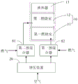
Referring to fig. 1 to 5, in an embodiment of the present invention, a burner includes:
a combustion body 10, the combustion body 10 having a first combustion chamber 11 and a second combustion chamber 12 which are communicated in this order; and the number of the first and second groups,
and the supercharging device 20 is provided with a first air outlet and a second air outlet, and the first air outlet is communicated with the first combustion chamber 11, is used for conveying gas to the first combustion chamber 11 and the second combustion chamber 12, and can control the flow rate of the gas conveyed to the second combustion chamber 12.
In this embodiment, the main features of the high temperature air combustion are: the chemical reaction needs to take place in a high temperature, low oxygen environment, with the reactants at a temperature above their auto-ignition temperature and the maximum temperature rise during combustion below their auto-ignition temperature, with the oxygen volume fraction being diluted to a very low concentration by the combustion products. Compared with conventional combustion, in the combustion state, the pyrolysis of fuel is inhibited, the flame thickness is thickened, and the flame front surface disappears, so that the temperature of the whole hearth is uniform, the combustion peak temperature is low, the noise is low, and the emission of pollutants NOx and CO is greatly reduced. However, achieving high temperature air combustion requires certain conditions: the oxygen concentration in most areas in the furnace is required to be ensured to be lower than a certain value, generally lower than 5% -10%, the gas is ensured to be fully combusted and uniformly combusted, the temperature is higher than the self-ignition point of the fuel, and the self-ignition is maintained. In addition, the following conditions are also achieved, and the high-temperature preheating of air and the matching of high-speed jet flow are the main modes for realizing high-temperature air combustion; the technical key for maintaining high-temperature air combustion is to entrain high-temperature flue gas and dilute combustion air jet.
The combustion main body 10 comprises a shell, a first combustion chamber 11 and a second combustion chamber 12 are sequentially formed on the shell, and a smoke exhaust port is formed in the shell; a preheating burner installed in the first combustion chamber 11; a heat exchanger 13 located between the smoke exhaust and the second combustion chamber 12; the burner further comprises an electric control assembly 90, and the combustion body 10 further comprises a water inlet pipe for introducing water into the gas water heater, a hot water outlet pipe for providing hot water to the outside, a smoke exhaust pipe connected with a smoke exhaust port, a gas inlet pipeline for introducing gas and an air inlet valve, wherein the existing gas inlet pipeline and the existing gas inlet valve are adopted, and detailed description is omitted. Wherein the preheating burner is used for heating the gas of the MILD combustion chamber. The preheating burner may be a honeycomb structure effective to prevent backfire during combustion, for example, the gas water heater may further include an igniter for igniting the gas injected from the preheating burner. The electric control assembly 90 is used for controlling the preheating burner to burn when the gas water heater is started, the gas and the air entering the first combustion chamber 11 are ignited and ignited by the preheating burner, and the mixed gas mixed with the gas and the air is burnt to heat the air in the first combustion chamber 11, so that high-temperature flue gas is formed. It will be appreciated that the air in the first combustion chamber 11 can be heated to a target temperature, i.e., the above-mentioned preset temperature, by controlling the heating temperature, so that the high-temperature preheating of the air is realized. After the high-temperature gas subjected to high-temperature preheating is sent into the second combustion chamber 12, fuel gas is injected into the second combustion chamber 12, the fuel gas is combined with the high-temperature gas, and the high-temperature gas ignites the fuel gas, so that MILD combustion is formed in the second combustion chamber 12. The first combustion chamber 11 is a preheating combustion chamber, and the second combustion chamber 12 is a high-temperature air combustion chamber.
In this embodiment, an air inlet duct, a fuel gas duct, and a mixing channel are further formed in the burner body, the mixing channel is respectively communicated with the air inlet duct and the fuel gas duct, the supercharging device 20 is disposed in the air inlet duct, when the gas water heater works, the supercharging device 20 pumps air outside the burner into the air inlet duct, the supercharging device 20 has two air outlets, namely, a first air outlet and a second air outlet, wherein the first air outlet is used for conveying air to the first combustion chamber 11, and the second air outlet is used for conveying air to the supercharging device 20. Wherein, the supercharging device 20 is an air compressor. By controlling the operation of the supercharging device 20, the total amount of air taken into the first combustion chamber 11 and the second combustion chamber 12 can be controlled. In this embodiment, the air compressor may pressurize the air output by the supercharging device 20, so that the air jet speed output to the second combustion chamber 12 may be increased.
Preheating the MILD intake air and increasing the speed of the MILD intake air are critical in order to create MILD combustion within the combustion chamber of the water heater. The existing fully premixed gas water heater adopts a fan to suck air, mixes the air with gas and then sprays the gas into a combustion chamber; the existing atmospheric gas water heater is strongly pumped to inject air through gas and then to spray the air into a combustion chamber, and strongly drum type air is sucked through a fan and then respectively sprayed into the combustion chamber. The existing gas water heaters adopt air distribution modes, the speed of airflow sprayed into a combustion chamber is usually not more than 2m/s, and the high-speed jet state required by MILD combustion cannot be achieved.
Therefore, in the present embodiment, the supercharging device 20 is provided, so that during the operation of the burner, the supercharging device 20 respectively supplies gas to the first combustion chamber 11 and the second combustion chamber 12, and when the gas is supplied to the second combustion chamber 12, the pressure of the gas supplied to the second combustion chamber 12 can be adjusted, so as to increase the pressure of the gas supplied to the second combustion chamber 12, and further ensure that the gas injection speed is controlled to meet the mld combustion condition, so that when the gas is injected to the second combustion chamber 12, the gas is combined with the high-temperature gas, and the high-temperature gas ignites the gas, thereby realizing the mld combustion in the second combustion chamber 12, and because the pressurized gas is supplied to the second combustion chamber 12 through the supercharging device 20, the gas supplied from the second combustion chamber 12 is in a high-speed injection state, and the mld combustion requirement is met. And a entrainment effect is formed in the second combustion chamber 12, so that an injection combustion area and a flue gas reflux area are formed in the second combustion chamber 12, part of high-temperature flue gas (waste gas rich in N2 and CO 2) is intensively circulated in the second combustion chamber 12 to dilute reactants, and then the injected fuel gas and air are fully diluted to form lower oxygen concentration, reduce the combustion reaction speed, maintain higher temperature of the second combustion chamber 12, ensure that the temperature is higher than the auto-ignition point of the fuel, realize auto-ignition and further realize high-temperature air combustion. The electronic control assembly 90 may also control the preheat burner to cease operation when the MILD burner temperature reaches above the MILD combustion light-off temperature while MILD combustion is occurring.
This embodiment preheats the air through high temperature and cooperates supercharging device 20 to pressurize gas, in order to be gas high-speed jet state, realize the entrainment high temperature flue gas and dilute, make 12 gas of second combustion chamber and air misce bene, the oxygen concentration of 12 second combustion chambers also can be balanced like this, and be less than a definite value, not only the gas can obtain abundant burning during the burning, just so reduced the emission of pollutant, and, also can the burning in the second combustion chamber 12 even, local combustion too flourishing and the problem of noise can not appear. In addition, the backflow of high-temperature flue gas is realized through high-speed jet entrainment, the temperature of the second combustion chamber 12 can be kept higher than the self-ignition point of the fuel, and the combustion can be maintained as long as the fuel gas is continuously introduced. The heat after combustion can exchange heat with the heat exchanger 13 of the gas water heater to realize the production of hot water. In the present embodiment, the air is pressurized by the air introduced by the pressurizing device 20, so as to increase the flow rate of the gas output to the second combustion chamber 12, increase the jet velocity of the pilot-air fuel injection (MILD), meet the MILD combustion requirement, and reduce the emission of CO and NOx.
It should be noted that the target temperature of the high-temperature preheated air cannot be too low, and cannot be lower than 600 degrees celsius as much as possible, and generally, the target temperature is controlled to 600 to 1200 degrees celsius, so that when the high-temperature gas contacts with the fuel gas in the second combustion chamber 12, better automatic combustion is realized, and ignition are no longer needed. Wherein, the target temperature can be achieved by controlling the heating time, controlling the ratio of the fuel gas and the air, preserving the heat, increasing the staying time of the high-temperature gas in the first combustion chamber 11, and the like. The injection speed of the gas delivered by the supercharging device 20 to the second combustion chamber 12 can be adjusted according to the requirement, specifically, the injection speed can be adjusted according to the preset temperature, the ambient temperature, the water inlet flow, the water outlet temperature, the ambient pressure, and the like, and the adjustment proportion and the adjustment process can be predetermined and set through experiments. Therefore, the jet velocity of the second combustion chamber 12 can be adjusted by controlling the gas pressure delivered to the second combustion chamber 12, and the high temperature flue gas can be entrained and the combustion/air jet can be diluted by adjusting the jet velocity, so that the high temperature air combustion can be maintained.
It will be appreciated that in this embodiment, the pressure increasing device 20 can supply pressurized air to the second combustion chamber 12 and supply gas to the first combustion chamber 11 and the second combustion chamber 12 in proportion to each other when the gas valve is opened. Or, the gas is increased at the same time, that is, a gas supercharging device 20 is arranged in the gas pipeline, and after the air and the gas are respectively pressurized, the air and the gas are respectively conveyed to the second combustion chamber 12 through the air pipeline and the gas pipeline. Alternatively, the supercharging device 20 may be used to supercharge a mixture of gas and air, and in this case, it may be implemented by a premixer provided in the combustion chamber, for example, in the first combustion chamber 11 or the second combustion chamber 12, and passing through the premixer. Particularly, can mix gas and air earlier, owing to provide the mist that contains gas and air through the premixer, the burning of igniteing is carried out to the mist to the preheating combustor, high temperature preheated air has been realized, again through pressurizeing the mist, the formation has the injection gas of certain jet velocity to cooperate and produces the entrainment effect, make the high temperature flue gas backward flow, realize on the one hand that keep warm and make the temperature be higher than the spontaneous combustion point of fuel, make the gas can the spontaneous combustion in the combustion chamber, on the other hand through the jet entrainment dilute air, make oxygen concentration be less than a definite value, realize the homogeneous combustion, thus, just make the high temperature air burning take place in the combustion chamber, can reach MILD burning requirement, reduce CO and NOx emission. That is to say, the technical scheme of this embodiment is favorable to having reached these two conditions simultaneously, realizes smoothly that high temperature air burns. And, the structure of this kind of combustor frame can be with the subassembly miniaturization that realizes the high temperature air burning for have more application space and value, the noise is low in addition, and the burning is abundant, and it is little to discharge waste gas pollution, when being applied to gas heater and including gas hanging stove etc. use gas burning to produce high temperature hot water and carry out relevant products and equipment that use such as family's shower and heating, not only satisfied the requirement, but also brought the abundant, low pollutant emission's of burning that the combustor did not possess in the current water heater effect.
Referring to fig. 2 or 3, in an embodiment, the burner further comprises:
and a first pressure regulating valve 30, wherein the air compressor and the first pressure regulating valve 30 are sequentially arranged between the second outlet of the supercharging device 20 and the second combustion chamber 12. In this embodiment, after the air compressor pressurizes the air, the first pressure regulating valve 30 may further increase or appropriately decrease the pressure of the air output to the second combustion chamber 12 according to the actual application requirement, so as to control the speed of the intake air entering the second combustion chamber 12 to the speed required for the pilot combustion when the pilot combustion is performed.
Referring to fig. 2 or 3, in an embodiment, the burner further comprises:
the pressure reducing valve 40 is arranged between the first air outlet and the pressure increasing device 20 in series, and the pressure reducing valve 40 is used for adjusting the air pressure delivered to the first combustion chamber 11.
In this embodiment, the pressure reducing valve 40 is used to adjust the air flow rates of the first outlet and the second outlet, and the air flow rate ratio delivered to the first combustion chamber 11 and the second combustion chamber 12 can be adjusted by adjusting the opening degree of the pressure reducing valve 40, for example, when the pressure reducing valve 40 is disposed between the first outlet and the first combustion chamber 11, the opening degree of the pressure reducing valve 40 is increased, the air ratio output to the first combustion chamber 11 is increased, and the air ratio output to the second combustion chamber 12 is decreased. In this way, it is ensured that the flow rates output to the first combustion chamber 11 and the second combustion chamber 12 can satisfy the requirements for the preheating combustion in the first combustion chamber 11 and the high-temperature air combustion in the second combustion chamber 12. For example, when the preheating combustion is performed, the air output from the pressure boosting device 20 may be output to the first combustion chamber 11, and when the MIILD combustion is performed and the preheating combustor is controlled to stop, the air output from the pressure boosting device 20 may be output to the second combustion chamber 12. In addition, the supercharging device is used for conveying gas to the first combustion chamber and the second combustion chamber, the supercharging device is used for supercharging air output to the second combustion chamber, the flow rate of the gas conveyed to the second combustion chamber can be controlled, the gas is pressurized to be in a high-speed jet flow state, and an injection gas with a certain jet flow speed is formed, so that high-temperature preheated air is achieved, an entrainment effect can be generated after the gas is conveyed to the second combustion chamber, high-temperature flue gas backflow is achieved, heat preservation is achieved, fuel gas in the combustion chamber can be ignited by self, air is diluted on the other hand, the oxygen concentration is lower than a certain value, uniform combustion is achieved, therefore, the MILD combustion requirement can be met, high-temperature air combustion can be achieved in the combustion chamber, and the emission of CO and NOx is reduced. By providing the pressure reducing valve 40, the flow rate of air output to the first combustion chamber 11 can be reduced, so that the air delivered to the first combustion can meet the demand for the preheat combustion.
Referring to fig. 2 or 3, in an embodiment, the burner includes:
a first gas valve 50 having a first gas outlet and a second gas outlet, wherein the first gas outlet is communicated with the first combustion chamber 11 and is used for delivering gas to the first combustion chamber 11;
the second gas outlet is communicated with the second combustion chamber 12 and is used for conveying gas to the second combustion chamber 12.
In this embodiment, the first gas valve 50 is used to control the gas flow delivered to the first combustion chamber 11 and the second combustion chamber 12, and the opening degree of the first gas valve 50 can be adjusted according to practical applications, such as preset temperature, inlet water temperature, etc., so as to ensure that the gas water heater can provide gas with corresponding flow during the working process, thereby implementing preheating combustion, mld combustion, etc. For example, when the gas water heater starts to operate, the opening degree of the first gas valve 50 is controlled to reach the ignition opening degree, then whether flame exists is detected through flame detection, if flame exists, the ignition is successful, then the opening degree of the first gas valve 50 is adjusted to enable the flow rate of the gas entering the first combustion chamber 11 to meet the preheating combustion, and cold water starts to be heated. Meanwhile, the heat load required by the gas water heater to heat the inlet water from the inlet water temperature to the set temperature can be calculated according to the inlet water temperature, the inlet water flow and the preset temperature of the gas water heater, the opening degree of a first gas valve 50 of the gas water heater is adjusted according to the heat load, and the flow transmitted to the first combustion chamber 11 and the second combustion chamber 12 is ensured to enable the outlet water temperature of the gas water heater to be consistent with the set temperature.
Referring to fig. 2 or 3, in an embodiment, the burner further comprises:
a second gas valve 60, wherein the second gas valve 60 is arranged in series between the first gas outlet and the first combustion chamber 11; alternatively, the second gas valve 60 is disposed in series between the second gas outlet and the second combustion chamber 12;
the second fuel valve 60 is used for adjusting the flow of the fuel gas delivered to the first combustion chamber 11 and the second combustion chamber 12.
In the present embodiment, the second gas valve 60 may be disposed between the first gas outlet and the first combustion chamber 11; or may be disposed in series between the second gas outlet and the second combustion chamber 12. By adjusting the opening degree of the second fuel valve 60, the gas flow rate ratio delivered to the first combustion chamber 11 and the second combustion chamber 12 can be adjusted. For example, when the pressure reducing valve 40 is provided between the first gas outlet and the first combustion chamber 11, the opening degree of the second gas valve 60 increases, the proportion of the air output to the first combustion chamber 11 increases, and the proportion of the air output to the second combustion chamber 12 decreases. Conversely, when the opening degree of the second fuel valve 60 is decreased, the proportion of the air output to the first combustion chamber 11 is decreased, and the proportion of the air output to the second combustion chamber 12 is increased. Similarly, when the pressure reducing valve 40 is provided between the second gas outlet and the second combustion chamber 12, the proportions of the first combustion chamber 11 and the second combustion chamber 12 can be adjusted. Therefore, the flow rates of the first air outlet and the second air outlet can be adjusted, namely the flow rates output to the first combustion chamber 11 and the second combustion chamber 12 are distributed, and the requirements of preheating combustion or high-temperature air combustion are met. For example, when the preheating combustion is performed, the air output from the pressure boosting device 20 may be output to the first combustion chamber 11, and when the MIILD combustion is performed and the preheating combustor is controlled to stop, the air output from the pressure boosting device 20 may be output to the second combustion chamber 12.
Referring to fig. 2 or 3, in an embodiment, the burner includes: and a gas pressure regulating valve 70 serially disposed between the second gas outlet and the second combustion chamber 12, wherein the gas pressure regulating valve 70 regulates a flow rate of gas to be supplied to the second combustion chamber 12.
In order to form MILD combustion in the combustion chamber of the water heater, the present embodiment uses the gas pressure regulating valve 70 to pressurize the gas output from the second gas outlet, so as to increase the gas flow rate output to the second combustion chamber 12, increase the jet velocity of MILD intake air, meet the MILD combustion requirement, and reduce the emission of CO and NOx. It can be understood that the pressure increasing device 20 and the gas pressure regulating valve 70 respectively regulate the pressure of the air and the gas output to the second combustion chamber 12 to increase the jet velocity of the mld intake air, and in practical applications, the pressure increasing device 20 and the gas pressure regulating valve 70 may be simultaneously arranged in the combustor, or any one of the pressure increasing device 20 and the gas pressure regulating valve 70 may be arranged, and the pressure of the intake air is regulated by controlling the pressure increasing device 20 and the gas pressure regulating valve 70, so that the speed of the mld intake air can be controlled to realize the mld combustion in the second combustion chamber 12.
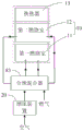
Referring to fig. 4, in an embodiment, the burner further includes:
a gas pipe; and
the first premixer 81 is configured to premix the air introduced from the first air outlet and the gas introduced from the gas pipe, and to supply the mixed gas to the first combustion chamber 11.
In the present embodiment, the first premixer 81 is disposed in the first combustion chamber 11, and since the mixed gas containing the fuel gas and the air is provided by the first premixer 81, the mixed gas is output to the first combustion chamber 11, so that the preheating burner ignites and combusts the mixed gas, thereby preheating the air at a high temperature.
Referring to fig. 4, in an embodiment, the burner further includes:
a gas pipe; and
and a second premixer 82 for premixing the air introduced from the second air outlet and the gas introduced from the gas pipe and supplying a mixed gas to the first combustion chamber 11.
In this embodiment, the second pre-mixer 82 is disposed in the second combustion chamber 12, since the second pre-mixer 82 provides the mixed gas containing the gas and the air, the mixed gas is output to the second combustion chamber 12, and the mixed gas delivered to the second combustion chamber 12 is pressurized by the burner, so as to form the injection gas with a certain jet velocity to cooperate to generate the entrainment effect, so that the high-temperature flue gas flows back, on one hand, the temperature is kept higher than the self-ignition point of the fuel, so that the gas in the combustion chamber can self-ignite, on the other hand, the diluted air is entrained by the jet, so that the oxygen concentration is lower than a certain value, and the uniform combustion is realized.
Referring to fig. 5, it can be understood that, in the above embodiment, the gas output to the first combustion chamber 11 and the second combustion chamber 12 may be premixed separately, or the total air and the gas may be mixed, that is, a full premixer 83 is provided, and the mixed gas is delivered to the first combustion chamber 11 and the second combustion chamber 12 through the gas delivery assembly 20, that is, the full premixing is achieved, and the adaptation may be specifically performed according to the requirement of the practical application and on the premise that the mld combustion can be guaranteed, which is not limited herein.
In order to facilitate the mixing of the gases when performing the full premixing, a mixed gas distribution chamber may be provided or formed in the preheating burner, an inlet of the mixed gas distribution chamber is communicated with the full premixer 83, and an outlet of the mixed gas distribution chamber is communicated with the first combustion chamber 11 and the second combustion chamber 12, so as to distribute the mixed gas ignition of the gases delivered to the first combustion chamber 11 and the second combustion chamber 12. The full premixer 83 mixes the introduced air and gas and outputs the mixed gas to the first combustion chamber 11 and the second combustion chamber 12, respectively. When the full premix is performed, as shown in fig. 5, the full premixer 83 is connected to the two outlets of the air feed unit 20, and the two outlets of the full premixer 83 communicate with the first combustion chamber 11 and the second combustion chamber 12, respectively. The air and/or fuel gas introduced into the full premixer 83 is pressurized gas, that is, the air supply assembly 20 first pressurizes the air and/or fuel gas and then outputs the pressurized air and/or fuel gas to the full premixer 83, and the full premixer 83 mixes the pressurized gas. Of course, in other embodiments, the air and the fuel gas may be mixed by the full premixer 83, and then the mixed gas may be output to the gas supply unit 20, and the gas supply unit 20 may further pressurize the mixed gas.
Referring to fig. 2 or 3, in an embodiment, the burner further comprises:
and the electric control assembly 90 is electrically connected with the burner and is used for controlling the burner to respectively convey gas to the first combustion chamber 11 and the second combustion chamber 12 and controlling the flow rate of the gas conveyed to the second combustion chamber 12, so that the gas is heated to a preset target temperature in the first combustion chamber 11 and then conveyed to the second combustion chamber 12 to be subjected to high-temperature air combustion.
In this embodiment, the electronic control assembly 90 includes a main controller and a driving assembly for driving the gas valve, the air compressor, etc., for example, a motor, a driving circuit, etc., the electronic control assembly 90 may further include a water inlet temperature sensor for detecting a water inlet temperature, a water outlet temperature sensor for detecting a water temperature, a flame temperature sensor for detecting a flame temperature, a flow meter for detecting a water inlet flow, etc., and the sensors are used to detect various parameters of the gas water heater during operation and output the parameters to the main controller, so that the main controller controls the operation of the burner, the preheating burner, etc., according to the parameters, the preset temperature, etc., to realize heating.
Referring to fig. 1 to 5, in an embodiment, the burner further includes:
and one end of the heat exchanger 13 is communicated with a cold water inlet pipe, the other end of the heat exchanger 13 is communicated with a hot water outlet pipe, and the heat exchanger 13 is used for absorbing heat generated by combustion in the first combustion chamber 11 and the second combustion chamber 12 and exchanging the absorbed heat with water in the heat exchanger 13.
In this embodiment, the cold water inlet pipe is used for introducing cold water from the outside to the gas water heater, and sending the cold water into the heat exchanger 13, the heat exchanger 13 absorbs heat generated by combustion of the preheating burner and combustion of the MILD and then heats the cold water into hot water, and the hot water is led out of the gas water heater through the hot water outlet pipe.
In the above embodiment, the temperature of the high-temperature preheated air may also be controlled in a heat preservation manner, and specifically, a heat insulation layer is disposed on the inner wall of the first combustion chamber 11. The temperature of the first combustion chamber 11 can be prevented from being released by arranging the heat insulation layer, so that heat preservation is carried out on the first combustion chamber 11, and the temperature of the high-temperature preheated air is conveniently controlled to reach the target temperature. And due to the heat preservation and insulation effects of the heat insulation layer, the phenomenon that the service life of external devices is influenced and the fuel utilization efficiency is reduced due to overheating of the shell 100 or heat transfer to the outside is avoided.
In the above embodiment, further, the burner may be further provided with a flame sensing device, the flame sensing device is disposed in the first combustion chamber 11 and is close to the preheating burner, the flame sensing device is configured to detect a flame of the preheating burner to determine whether the preheating burner is in a combustion state, and when the preheating burner is determined not to be in the combustion state, the preheating burner is controlled to be re-ignited.
In the above embodiment, further, the burner may further be provided with a temperature measuring device, and the temperature measuring device is disposed in the first combustion chamber 11. The temperature measuring device is used for detecting the temperature in the first combustion chamber 11 so as to determine whether the temperature of the gas in the first combustion chamber 11 reaches the target temperature, if not, the temperature in the first combustion chamber 11 needs to be increased, and the air inlet amount can be controlled or the gas-air ratio of the premixer can be controlled to realize temperature adjustment. By detecting the temperature, the heat load generated by preheating combustion in the first combustion chamber 11 can be automatically adjusted according to the air amount required by combustion of the MILD to achieve the effect of quickly preheating air, and simultaneously, low CO & NOX emission in the whole combustion process is ensured.
Referring to fig. 1 to 5, the working principle of the burner of the present invention applied to a gas water heater is illustrated in combination with the above-mentioned embodiment of the burner:
when the water heater is started, the first gas valve 50 and the supercharging device 20 supply air and gas mixed according to a certain proportion to the first combustion chamber 11, the ignition device ignites the gas, the combustion starts in the first combustion chamber 11, the fan acts and sucks air required by the preheating combustion, cold air and high-temperature flue gas generated by the combustion of the first combustion chamber 11 are stirred and mixed for a plurality of times in the first combustion chamber 11 to form high-temperature flue gas, when the temperature of the high-temperature flue gas reaches the temperature required by the MILD combustion, the first gas valve 50 supplies the gas to the second combustion chamber 12, the supercharging device 20 compresses the sucked air by the air compressor and outputs the compressed air to the second combustion chamber 12, meanwhile, the gas required by the MILD combustion is injected to the second combustion chamber 12 by the second gas valve 60, the gas, the compressed air is combined with the high-temperature gas, the high-temperature gas ignites the gas, and MILD combustion is formed in the second combustion chamber 12, because the compressed air has a certain jet flow velocity, an entrainment effect can be formed in the second combustion chamber 12, so that an injection combustion area and a smoke backflow area are formed in the second combustion chamber 12, part of smoke is intensively circulated in the second combustion chamber 12, the injected air and the injected smoke are fully diluted to form lower oxygen concentration, the combustion reaction velocity is reduced, the higher temperature of the second combustion chamber 12 is maintained, the temperature is higher than the spontaneous combustion point of the fuel, and the spontaneous combustion is realized. As such, the present embodiment achieves high temperature air combustion (mld combustion): high-temperature preheating air is matched with high-speed jet flow to realize entrainment of high-temperature flue gas and dilution of air jet flow, so that the oxygen concentration is lower than a certain value, and the temperature is higher than the self-ignition point of fuel. The heat after burning can exchange heat with the heat exchanger 13 of the gas water heater and then be discharged to the outside so as to realize the production of hot water.
It can be understood that, because the burner is adopted in the gas water heater, the gas water heater can effectively reduce the emission of CO and NOx and reduce the noise of the gas water heater.
The utility model also provides a gas heater, gas heater include above-mentioned combustor, the heat exchanger passes through the heat that the combustor produced makes hot water. The detailed structure of the burner can refer to the above embodiments, and is not described herein; it can be understood that, because the utility model discloses above-mentioned combustor has been used among the gas heater, consequently, the utility model discloses gas heater's embodiment includes all technical scheme of the whole embodiments of above-mentioned combustor, and the technical effect that reaches is also identical, no longer gives unnecessary details here.
The above only is the preferred embodiment of the present invention, not limiting the scope of the present invention, all the equivalent structure changes made by the contents of the specification and the drawings under the inventive concept of the present invention, or the direct/indirect application in other related technical fields are included in the patent protection scope of the present invention.
Claims (13)
1. A burner, characterized in that it comprises:
the combustion device comprises a combustion main body, a first combustion chamber and a second combustion chamber, wherein the first combustion chamber and the second combustion chamber are sequentially communicated; and the number of the first and second groups,
and the supercharging device is provided with a first air outlet and a second air outlet, and the first air outlet is communicated with the first combustion chamber and is used for conveying gas to the first combustion chamber and the second combustion chamber and controlling the flow rate of the gas conveyed to the second combustion chamber.
2. The burner of claim 1, further comprising:
and the inlet of the first pressure regulating valve is communicated with the second air outlet of the supercharging device, and the outlet of the first pressure regulating valve is communicated with the second combustion chamber so as to regulate the air flow rate of the air in the second combustion chamber when the air is injected into the second combustion chamber.
3. The burner of claim 2, wherein the pressure boosting device is an air compressor.
4. The burner of claim 1, further comprising:
the pressure reducing valve is arranged between the first air outlet and the supercharging device in series and used for adjusting the air pressure conveyed to the first combustion chamber.
5. The burner of claim 1, further comprising:
the first gas valve is provided with a first gas outlet and a second gas outlet, and the first gas outlet is communicated with the first combustion chamber and used for conveying gas to the first combustion chamber;
the second fuel gas outlet is communicated with the second combustion chamber and is used for conveying fuel gas to the second combustion chamber.
6. The burner of claim 5, further comprising:
the second fuel gas valve is arranged between the first fuel gas outlet and the first combustion chamber in series; alternatively, the second gas valve is disposed in series between the second gas outlet and the second combustion chamber;
the second fuel gas valve is used for adjusting the gas flow delivered to the first combustion chamber and the second combustion chamber.
7. The burner of claim 6, further comprising:
and the gas pressure regulating valve is arranged between the second gas outlet and the second combustion chamber in series and is used for regulating the gas flow rate of the gas conveyed to the second combustion chamber.
8. The burner of claim 1, further comprising:
a gas pipe; and the number of the first and second groups,
the first premixer is used for premixing the air accessed from the first air outlet and the fuel gas accessed from the fuel gas pipe and providing mixed gas for the first combustion chamber.
9. The burner of claim 1, further comprising:
a gas pipe; and the number of the first and second groups,
and the second premixer is used for premixing the air accessed from the second air outlet and the fuel gas accessed from the fuel gas pipe and providing mixed gas for the second combustion chamber.
10. The burner of claim 1, wherein the first combustion chamber is a preheat combustion chamber and the second combustion chamber is a high temperature air combustion chamber.
11. The burner of claim 1, further comprising:
and the electric control assembly is electrically connected with the supercharging device and used for controlling the supercharging device to respectively convey gas to the first combustion chamber and the second combustion chamber and controlling the flow rate of the gas conveyed to the second combustion chamber, so that the gas is heated in the first combustion chamber to a preset target temperature and then conveyed to the second combustion chamber to be subjected to high-temperature air combustion.
12. The burner of any of claims 1-11, wherein the burner further comprises:
and one end of the heat exchanger is communicated with the cold water inlet pipe, the other end of the heat exchanger is communicated with the hot water outlet pipe, and the heat exchanger is used for absorbing heat generated by combustion of the first combustion chamber and the second combustion chamber and exchanging the absorbed heat with water in the heat exchanger.
13. A gas water heater comprising a burner as claimed in any one of claims 1 to 12.
Priority Applications (1)
| Application Number | Priority Date | Filing Date | Title |
|---|---|---|---|
| CN202023205930.0U CN214307646U (en) | 2020-12-25 | 2020-12-25 | Combustor and gas water heater |
Applications Claiming Priority (1)
| Application Number | Priority Date | Filing Date | Title |
|---|---|---|---|
| CN202023205930.0U CN214307646U (en) | 2020-12-25 | 2020-12-25 | Combustor and gas water heater |
Publications (1)
| Publication Number | Publication Date |
|---|---|
| CN214307646U true CN214307646U (en) | 2021-09-28 |
Family
ID=77862553
Family Applications (1)
| Application Number | Title | Priority Date | Filing Date |
|---|---|---|---|
| CN202023205930.0U Active CN214307646U (en) | 2020-12-25 | 2020-12-25 | Combustor and gas water heater |
Country Status (1)
| Country | Link |
|---|---|
| CN (1) | CN214307646U (en) |
Cited By (1)
| Publication number | Priority date | Publication date | Assignee | Title |
|---|---|---|---|---|
| CN114688741A (en) * | 2020-12-25 | 2022-07-01 | 芜湖美的厨卫电器制造有限公司 | Combustor and gas water heater |
-
2020
- 2020-12-25 CN CN202023205930.0U patent/CN214307646U/en active Active
Cited By (1)
| Publication number | Priority date | Publication date | Assignee | Title |
|---|---|---|---|---|
| CN114688741A (en) * | 2020-12-25 | 2022-07-01 | 芜湖美的厨卫电器制造有限公司 | Combustor and gas water heater |
Similar Documents
| Publication | Publication Date | Title |
|---|---|---|
| CN112682781B (en) | Combustor and gas water heater | |
| US4800866A (en) | Low NOX radiant tube burner and method | |
| CN216619819U (en) | Combustor subassembly and gas hot water equipment | |
| CN214307646U (en) | Combustor and gas water heater | |
| CN216619818U (en) | Combustor subassembly and gas heater | |
| CN110822705B (en) | Combustion heat exchange device, gas wall-mounted furnace and gas water heater | |
| CN108954799B (en) | Combustion heat exchange device, gas wall-mounted furnace and gas water heater | |
| CN114688532A (en) | Combustor and gas water heater | |
| CN109579009A (en) | The burner apparatus of low-nitrogen oxide discharging | |
| CN114688531A (en) | Combustor and gas water heater | |
| WO2020221366A1 (en) | Combustion assembly and wall-mounted stove | |
| CN215175014U (en) | Combustor and gas heater | |
| CN114459029A (en) | Combustor and gas equipment | |
| CN210486040U (en) | Combustion heat exchange equipment | |
| CN115560325A (en) | Combustor and gas water heating equipment | |
| CN208671326U (en) | Combustion heat-exchange device, burnt gas wall hanging furnace and gas heater | |
| CN216619817U (en) | Combustor and water heater | |
| CN115560468A (en) | Gas water heater, control method thereof and computer-readable storage medium | |
| CN114688741A (en) | Combustor and gas water heater | |
| CN107013911B (en) | Method of catalytic combustion | |
| CN215723199U (en) | Combustor and gas equipment | |
| WO2023274381A1 (en) | Combustor assembly and gas water heater device | |
| CN216619816U (en) | Combustor and water heater | |
| CN115560487A (en) | Gas water heating equipment, control method and device thereof and computer readable storage medium | |
| CN115560322A (en) | Combustor and water heater |
Legal Events
| Date | Code | Title | Description |
|---|---|---|---|
| GR01 | Patent grant | ||
| GR01 | Patent grant |