CN214276451U - Cereal drying device for agricultural production - Google Patents
Cereal drying device for agricultural production Download PDFInfo
- Publication number
- CN214276451U CN214276451U CN202022857339.7U CN202022857339U CN214276451U CN 214276451 U CN214276451 U CN 214276451U CN 202022857339 U CN202022857339 U CN 202022857339U CN 214276451 U CN214276451 U CN 214276451U
- Authority
- CN
- China
- Prior art keywords
- oven
- agricultural production
- drying
- cereal
- drying device
- Prior art date
- Legal status (The legal status is an assumption and is not a legal conclusion. Google has not performed a legal analysis and makes no representation as to the accuracy of the status listed.)
- Expired - Fee Related
Links
- 235000013339 cereals Nutrition 0.000 title claims abstract description 60
- 238000001035 drying Methods 0.000 title claims abstract description 53
- 238000012271 agricultural production Methods 0.000 title claims abstract description 18
- 235000017166 Bambusa arundinacea Nutrition 0.000 claims description 6
- 235000017491 Bambusa tulda Nutrition 0.000 claims description 6
- 241001330002 Bambuseae Species 0.000 claims description 6
- 235000015334 Phyllostachys viridis Nutrition 0.000 claims description 6
- 239000011425 bamboo Substances 0.000 claims description 6
- 244000309464 bull Species 0.000 claims description 5
- 239000011229 interlayer Substances 0.000 claims description 4
- 238000004321 preservation Methods 0.000 claims description 3
- 239000013590 bulk material Substances 0.000 abstract description 16
- 238000005485 electric heating Methods 0.000 abstract description 10
- 238000010981 drying operation Methods 0.000 abstract description 3
- 238000000034 method Methods 0.000 description 5
- 238000003860 storage Methods 0.000 description 5
- 238000007599 discharging Methods 0.000 description 4
- 239000000463 material Substances 0.000 description 4
- 230000008569 process Effects 0.000 description 4
- 241000196324 Embryophyta Species 0.000 description 3
- 230000009471 action Effects 0.000 description 3
- 230000005484 gravity Effects 0.000 description 3
- 238000004519 manufacturing process Methods 0.000 description 3
- 241001465754 Metazoa Species 0.000 description 2
- 230000008901 benefit Effects 0.000 description 2
- 230000000694 effects Effects 0.000 description 2
- 238000005096 rolling process Methods 0.000 description 2
- 238000009423 ventilation Methods 0.000 description 2
- 230000009286 beneficial effect Effects 0.000 description 1
- 238000010276 construction Methods 0.000 description 1
- 238000005520 cutting process Methods 0.000 description 1
- 238000010586 diagram Methods 0.000 description 1
- 235000013305 food Nutrition 0.000 description 1
- 238000012986 modification Methods 0.000 description 1
- 230000004048 modification Effects 0.000 description 1
Images


Landscapes
- Drying Of Solid Materials (AREA)
Abstract
The utility model discloses a cereal drying device for agricultural production, which comprises a base, an oven and a drying oven, wherein the oven is fixedly arranged above the base through a plurality of support rods, the drying oven is fixedly arranged on the base and positioned on the side of the oven, the upper end of the drying oven is open, the top of the inner cavity of the oven is fixedly provided with a bulk material barrel, the bottom of the bulk material barrel is fixedly connected with a lifting barrel, the side wall of the bulk material barrel is provided with a plurality of discharge holes at equal intervals in the circumferential direction, the inner wall of the oven is fixedly provided with an annular air outlet box, the end surface of the annular air outlet box towards the central line of the oven is uniformly provided with a plurality of air outlet nozzles in the circumferential direction from top to bottom, the outer wall of the oven is fixedly provided with a hot air blower, a plurality of guide electric heating plates for carrying out secondary drying operation on the cereal are alternately and obliquely arranged at equal intervals from top to bottom in the drying oven, the device has reasonable structural layout, the operation is simple, the use is convenient, and the cereal can be efficiently and conveniently dried, high efficiency and effectual need not long-time consuming waiting, improves agricultural production efficiency greatly.
Description
Technical Field
The utility model relates to an agricultural production technical field specifically is a cereal drying device for agricultural production.
Background
The agriculture is an industry for obtaining products by artificial cultivation by utilizing growth and development rules of animals and plants, and is a basic industry for supporting national economic construction and development; the land is an irreplaceable basic production material in agriculture, the working objects are mainly living animals and plants, the production time is inconsistent with the working time, the land is greatly influenced by natural conditions, and the land has obvious regionality and seasonality. Agriculture is the source and the root of human clothing and food, and is the first condition for all production.
The seed of plant can be obtained usually among the agricultural production, we refer to this type of seed as cereal commonly, and the peasant often need carry out drying process and just can store to the warehouse after collecting cereal, and current drying mode to cereal usually dries naturally, need consume a large amount of time to the effect is still relatively poor, seriously influences agricultural production efficiency, consequently, the utility model provides a cereal drying device for agricultural production solves above-mentioned problem.
SUMMERY OF THE UTILITY MODEL
An embodiment of the utility model aims to provide a cereal drying device for agricultural production to solve above-mentioned problem.
In order to achieve the above object, the utility model provides a following technical scheme:
a grain drying device for agricultural production comprises a base, an oven and a drying box, wherein the oven is fixedly arranged above the base through a plurality of support rods, the drying box is fixedly arranged on the base and is positioned on the side of the oven, the upper end of the drying box is open, a bulk material barrel is fixedly arranged at the top of an inner cavity of the oven, a lifting barrel is fixedly connected at the bottom of the bulk material barrel, a rotating rod is rotatably arranged at the top of the inner cavity of the bulk material barrel through a bearing, the lower end of the rotating rod extends to the lower part of the inner cavity of the oven, a lifting auger is fixedly arranged on the rotating rod, a plurality of discharge holes are circumferentially and equidistantly arranged on the side wall of the bulk material barrel, an annular air outlet box is fixedly arranged on the inner wall of the oven, a plurality of air outlets are uniformly arranged on the end face of the annular air outlet box, which faces the central line of the oven, from top to, the lower part of the side wall of the drying oven is provided with a first discharge hole, a plurality of guide electric heating plates for performing second drying operation on the grains are alternately and obliquely arranged in the drying oven from top to bottom at equal intervals, and the lower part of the side wall of the drying oven is provided with a second discharge hole.
In one alternative: oven top is equipped with the feeder hopper that is used for throwing in cereal to its inside, and the oven bottom evenly is equipped with the ventilation hole, all is equipped with the filter screen that is used for preventing cereal and spills in every ventilation hole.
In one alternative: a plurality of rollers are symmetrically arranged at the bottom of the base and are self-locking rollers.
In one alternative: and a heat-insulating interlayer is arranged in the side wall of the oven.
In one alternative: the top of the oven is fixedly provided with a driving motor, and an output shaft of the driving motor extends into the oven and is connected with the upper end of the rotating rod.
Compared with the prior art, the embodiment of the utility model has the following beneficial effects:
1. the device structural layout is reasonable, easy operation, and convenient to use can dry cereal high-efficiently conveniently, and is efficient and effectual, need not long-time consuming time and waits for, improves agricultural production efficiency greatly, has good economic benefits and practical meaning.
Drawings
Fig. 1 is a schematic structural diagram of an embodiment of the present invention.
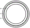
Fig. 2 is the schematic view of the transverse cutting structure between the oven and the annular air outlet box in the embodiment of the present invention.
Fig. 3 is an enlarged view of a portion a in fig. 1.
Notations for reference numerals: 1-roller, 2-base, 3-support rod, 4-oven, 5-heat preservation interlayer, 6-annular air outlet box, 7-air outlet nozzle, 8-lifting cylinder, 9-rotating rod, 10-discharging hole, 11-material dispersing cylinder, 12-feeding hopper, 13-driving motor, 14-lifting flood dragon, 15-first discharging hole, 16-drying box, 17-material guiding electric heating plate, 18-second discharging hole, 19-air hole, 20-filter screen, 21-hot air blower and 22-air guide pipe.
Detailed Description
In order to make the objects, technical solutions and advantages of the present invention more clearly understood, the present invention is further described in detail below with reference to the accompanying drawings and embodiments. It should be understood that the specific embodiments described herein are merely illustrative of the invention and are not intended to limit the invention.
Example 1
Referring to fig. 1-3, in the embodiment of the present invention, a grain drying device for agricultural production comprises a base 2, an oven 4 and a drying box 16, wherein the oven 4 is fixedly disposed above the base 2 through a plurality of support rods 3, the drying box 16 is fixedly disposed on the base 2 and located at the side of the oven 4, the upper end of the drying box 16 is open, a bulk material cylinder 11 is fixedly disposed at the top of an inner cavity of the oven 4, a lifting cylinder 8 is fixedly connected to the bottom of the bulk material cylinder 11, one end of the lifting cylinder 8, which is far away from a discharge hole 10, extends to the lower portion of the inner cavity of the oven 4, and keeps a certain gap with the lower portion, the lifting cylinder 8 is communicated with the interior of the bulk material cylinder 11, a rotating rod 9 is rotatably mounted at the top of the inner cavity of the bulk material cylinder 11 through a bearing, the lower end of the rotating rod 9 extends to the lower portion of the inner cavity of the oven 4, a lifting auger 14 for lifting the grains at the bottom of the inner cavity of the oven 4 into the bulk material cylinder 11 is fixedly disposed on the rotating rod 9, a plurality of discharge holes 10 for discharging the grains are disposed on the side wall of the bulk material cylinder 11 in an annular direction, oven 4 top fixed mounting has driving motor 13, and driving motor 13's output shaft extends to in oven 4 and is connected with bull stick 9 upper end, drives through driving motor 13 that bull stick 9 rotates and then makes promotion flood dragon 14 promote the cereal of oven 4 inner chamber bottom to the bulk cargo section of thick bamboo 11 in, then each bin outlet 10 discharge that is equipped with on the 11 lateral walls of bulk cargo section of thick bamboo of follow again gives off and opens.
An annular air outlet box 6 is fixedly arranged on the inner wall of the oven 4, a plurality of air outlet nozzles 7 are uniformly arranged on the end face, facing the central line of the oven 4, of the annular air outlet box 6 from top to bottom in an annular mode, a hot air blower 21 is fixedly arranged on the outer wall of the oven 4, an air guide pipe 22 is fixedly connected to the air outlet end of the hot air blower 21, one end, far away from the hot air blower 21, of the air guide pipe 22 extends into the annular air outlet box 6, hot air is conveyed into the annular air outlet box 6 through the hot air blower 21, then the hot air is uniformly sprayed out from each air outlet nozzle 7 to comprehensively dry grains scattered and descending from the bulk material barrel 11, a first discharge port 15 is arranged at the lower part of the side wall of the oven 4, the first discharge port 15 is positioned above the drying box 16 and is provided with a first discharge valve, a plurality of guide electric heating plates 17 for performing second drying operation on the grains are alternately and obliquely arranged from top to bottom in the drying box 16, after the grains are dried in the oven 4 for a period of time, open first bleeder valve, cereal in the oven 4 falls to the drying cabinet 16 in through first discharge gate 15 and rolls the whereabouts on polylith guide electric plate 17 in proper order under the action of gravity, because guide electric plate 17 surface temperature is higher, cereal can be all-round toasted at the rolling in-process on guide electric plate 17, and then reach the purpose of drying cereal, the cereal that dries is finally fallen to the drying cabinet 16 bottom and is kept in order to treat follow-up warehouse entry storage, drying cabinet 16 lateral wall lower part is equipped with second discharge gate 18, be equipped with the second bleeder valve on the second discharge gate 18.
Further, the top of the oven 4 is provided with a feed hopper 12 for feeding grains into the oven, the bottom of the oven 4 is uniformly provided with vent holes 19, and each vent hole 19 is internally provided with a filter screen 20 for preventing grains from leaking.
Furthermore, in order to move the device conveniently, a plurality of rollers 1 are symmetrically arranged at the bottom of the base 2, and the rollers 1 are self-locking rollers.
When the grain drying oven is used, firstly, grains to be dried are put into the drying oven 4 through the feeding hopper 12, then the driving motor 13 and the hot air blower 21 are started, the driving motor 13 drives the rotating rod 9 to rotate so that the lifting flood dragon 14 lifts the grains at the bottom of the inner cavity of the drying oven 4 into the dispersing barrel 11, then the grains are discharged and dispersed from the discharge holes 10 arranged on the side wall of the dispersing barrel 11, in the process that the grains fall from a high place, the hot air blower 21 conveys hot air into the annular air outlet box 6, then the hot air is uniformly sprayed out from the air outlet nozzles 7 so as to comprehensively dry the grains, after the grains are dried in the drying oven 4 for a period of time, the first discharge valve is opened, the grains in the drying oven 4 fall into the drying box 16 through the first discharge port 15 and sequentially roll on the plurality of guide electric heating plates 17 under the action of gravity, and the temperature of the surfaces of the guide electric heating plates 17 is higher, the grains can be comprehensively baked in the process that the grains roll on the guide electric heating plates 17, and then the purpose of drying the grains is achieved, and the dried grains finally fall to the bottom of the drying box 16 for temporary storage for subsequent warehousing and storage.
Example 2
Further, in order to reduce heat loss, keep the temperature in the oven 4 high, and improve the drying rate and effect, a heat preservation interlayer 5 is arranged in the side wall of the oven 4.
The utility model discloses a theory of operation is: when the utility model is used, firstly, the grain to be dried is put into the oven 4 through the feed hopper 12, then the driving motor 13 and the air heater 21 are started, the driving motor 13 drives the rotating rod 9 to rotate so as to lead the lifting auger 14 to lift the grain at the bottom of the inner cavity of the oven 4 into the bulk material barrel 11, then the grain is discharged and dispersed from each discharge hole 10 arranged on the side wall of the bulk material barrel 11, in the process that the grain falls from the high place, the air heater 21 conveys hot air into the annular air outlet box 6, then the grain is evenly sprayed out from each air outlet nozzle 7 so as to carry out all-round drying on the grain, when the grain is dried in the oven 4 for a period of time, the first discharge valve is opened, the grain in the oven 4 falls into the drying box 16 through the first discharge hole 15 and rolls on the plurality of guide electric heating plates 17 in turn under the action of gravity, because the surface temperature of the guide electric heating plates 17 is higher, the grains can be baked in all directions in the process of rolling on the material guide electric heating plate 17, so that the purpose of drying the grains is achieved, and the dried grains finally fall to the bottom of the drying box 16 for temporary storage for later warehousing and storage.
The above description is only exemplary of the present invention and should not be taken as limiting the scope of the present invention, as any modifications, equivalents, improvements and the like made within the spirit and principles of the present invention are intended to be included within the scope of the present invention.
Claims (5)
1. The utility model provides a cereal drying device for agricultural production, including base (2), oven (4) and drying cabinet (16), a serial communication port, oven (4) are fixed to be located base (2) top through many spinal branchs pole (3), drying cabinet (16) are fixed to be located base (2) and are located oven (4) side, drying cabinet (16) upper end is uncovered, oven (4) inner chamber top fixed mounting has bulk cargo section of thick bamboo (11), bulk cargo section of thick bamboo (11) bottom fixed connection has a lifting cylinder (8), bulk cargo section of thick bamboo (11) inner chamber top is rotated through the bearing and is installed bull stick (9), bull stick (9) lower extreme extends to oven (4) inner chamber lower part, fixedly on bull stick (9) be equipped with promotion flood dragon (14), it is equipped with a plurality of relief holes (10) to encircle to the equidistance on bulk cargo section of thick bamboo (11) lateral wall;
fixed mounting has annular air-out box (6) on oven (4) inner wall, annular air-out box (6) evenly is equipped with a plurality of air outlet nozzle (7) by the ring shape from the top down on the terminal surface towards oven (4) central line, fixed mounting has air heater (21) on oven (4) outer wall, fixedly connected with guide duct (22) are served to the air-out of air heater (21), the one end that air heater (21) were kept away from in guide duct (22) extends to annular air-out box (6), oven (4) lateral wall lower part is equipped with first discharge gate (15), be equipped with guide electric plate (17) that the polylith was used for carrying out the second stoving operation to cereal by last equidistant slant in turn in drying cabinet (16), drying cabinet (16) lateral wall lower part is equipped with second discharge gate (18).
2. The grain drying device for agricultural production according to claim 1, wherein a feed hopper (12) for feeding grains into the oven (4) is arranged at the top of the oven, vent holes (19) are uniformly formed in the bottom of the oven (4), and a filter screen (20) for preventing grains from leaking out is arranged in each vent hole (19).
3. The grain drying device for agricultural production according to claim 1, wherein a plurality of rollers (1) are symmetrically arranged at the bottom of the base (2), and the rollers (1) are self-locking rollers.
4. The grain drying device for agricultural production according to claim 1, wherein a heat preservation interlayer (5) is arranged in the side wall of the oven (4).
5. The grain drying device for agricultural production according to any one of claims 1 to 4, wherein a driving motor (13) is fixedly mounted at the top of the oven (4), and an output shaft of the driving motor (13) extends into the oven (4) and is connected with the upper end of the rotating rod (9).
Priority Applications (1)
| Application Number | Priority Date | Filing Date | Title |
|---|---|---|---|
| CN202022857339.7U CN214276451U (en) | 2020-12-02 | 2020-12-02 | Cereal drying device for agricultural production |
Applications Claiming Priority (1)
| Application Number | Priority Date | Filing Date | Title |
|---|---|---|---|
| CN202022857339.7U CN214276451U (en) | 2020-12-02 | 2020-12-02 | Cereal drying device for agricultural production |
Publications (1)
| Publication Number | Publication Date |
|---|---|
| CN214276451U true CN214276451U (en) | 2021-09-24 |
Family
ID=77778527
Family Applications (1)
| Application Number | Title | Priority Date | Filing Date |
|---|---|---|---|
| CN202022857339.7U Expired - Fee Related CN214276451U (en) | 2020-12-02 | 2020-12-02 | Cereal drying device for agricultural production |
Country Status (1)
| Country | Link |
|---|---|
| CN (1) | CN214276451U (en) |
-
2020
- 2020-12-02 CN CN202022857339.7U patent/CN214276451U/en not_active Expired - Fee Related
Similar Documents
| Publication | Publication Date | Title |
|---|---|---|
| CN204085090U (en) | A kind of biological organic fertilizer dryer | |
| CN108848955B (en) | Agricultural grain storage bin | |
| CN108759378A (en) | A kind of drum-type organic fertilizer dryer | |
| CN207849990U (en) | A kind of bio-organic fertilizer high efficiency drying device | |
| CN206182259U (en) | Production line of garrulous tea | |
| CN111412726A (en) | Novel cereal is dried device | |
| CN109442875A (en) | A kind of seed rapid moisture removal equipment | |
| CN206024460U (en) | Farming crop seed drying device | |
| CN214276451U (en) | Cereal drying device for agricultural production | |
| CN209415990U (en) | A kind of rice drying continuous type drying device | |
| CN210580774U (en) | Double mode electric heating grain drying-machine | |
| CN207365592U (en) | A kind of New drying device for preboiled rice | |
| CN206974112U (en) | A kind of chicken manure drying plant beneficial to deodorization | |
| CN207163096U (en) | A kind of food processing drying baker | |
| CN205671441U (en) | The uniform drying plant of peanut | |
| CN204787702U (en) | Novel grain drying machine | |
| CN208205747U (en) | Grain drying device | |
| CN205980682U (en) | Fodder circulation drying device | |
| CN206755823U (en) | A kind of wheat seed dryer | |
| CN206751634U (en) | A kind of energy-efficient excrement apparatus for drying | |
| CN209978573U (en) | Drying device for environment-friendly agricultural production | |
| CN203222561U (en) | Wet pelletizer for bio-organic fertilizer | |
| CN207763399U (en) | A kind of grain drying to clean | |
| CN209749777U (en) | Equipment for promoting after-ripening of camellia fruits and camellia seeds | |
| CN207940230U (en) | A kind of fresh water fish feed delivery device |
Legal Events
| Date | Code | Title | Description |
|---|---|---|---|
| GR01 | Patent grant | ||
| GR01 | Patent grant | ||
| CF01 | Termination of patent right due to non-payment of annual fee | ||
| CF01 | Termination of patent right due to non-payment of annual fee |
Granted publication date: 20210924 |