CN214243248U - Winding drum convenient for yarn clamping for textile machinery - Google Patents
Winding drum convenient for yarn clamping for textile machinery Download PDFInfo
- Publication number
- CN214243248U CN214243248U CN202023098243.3U CN202023098243U CN214243248U CN 214243248 U CN214243248 U CN 214243248U CN 202023098243 U CN202023098243 U CN 202023098243U CN 214243248 U CN214243248 U CN 214243248U
- Authority
- CN
- China
- Prior art keywords
- fixedly connected
- belt pulley
- support frame
- connecting plate
- reel
- Prior art date
- Legal status (The legal status is an assumption and is not a legal conclusion. Google has not performed a legal analysis and makes no representation as to the accuracy of the status listed.)
- Expired - Fee Related
Links
- 239000004753 textile Substances 0.000 title claims abstract description 22
- 238000004804 winding Methods 0.000 title claims abstract description 21
- 230000007246 mechanism Effects 0.000 claims description 5
- 238000005516 engineering process Methods 0.000 abstract description 6
- 241000252185 Cobitidae Species 0.000 abstract 1
- 238000009987 spinning Methods 0.000 description 6
- 230000000694 effects Effects 0.000 description 2
- 239000000835 fiber Substances 0.000 description 2
- 238000009941 weaving Methods 0.000 description 2
- 230000009286 beneficial effect Effects 0.000 description 1
- 238000009984 hand spinning Methods 0.000 description 1
- 239000004745 nonwoven fabric Substances 0.000 description 1
Images


Landscapes
- Storage Of Web-Like Or Filamentary Materials (AREA)
Abstract
The utility model belongs to the technical field of the textile technology and specifically relates to a reel for textile machinery convenient to card line, the loach carrying platform comprises a supporting fram, rotate through the bearing on the support frame and be connected with the reel, the first belt pulley of reel upper end fixedly connected with, fixedly connected with connecting plate on the support frame, rotate through the bearing on the connecting plate and be connected with the pivot, fixedly connected with second belt pulley in the pivot, the second belt pulley with the cover is equipped with the belt between the first belt pulley, reciprocating screw has seted up in the pivot, threaded connection has the thread bush on the reciprocating screw, fixedly connected with spacing ring on the thread bush, be provided with stop gear on the spacing ring, support frame lower extreme fixedly connected with fixed column. The utility model discloses have the even winding of line on the reel, block the line, prevent when coiling that not hard up characteristics appear in the line.
Description
Technical Field
The utility model relates to the field of textile technology, especially, relate to a reel for textile machinery convenient to card line.
Background
The present textile is not only the traditional hand spinning and weaving, but also includesNon-woven fabricThe technology, the modern three-dimensional weaving technology, the modern electrostatic nano-net forming technology and the like. Therefore, modern spinning refers to a multi-scale structure processing technology of fibers or fiber aggregates, when a textile machine is used for spinning, a textile wire needs to be coiled, but when an existing winding drum is coiled, the existing winding drum cannot tightly clamp and wind the wire, and the coiled textile wire is easy to loosen.
SUMMERY OF THE UTILITY MODEL
The utility model aims at solving the problem that the existing spinning thread coiling easily causes the loosening of the spinning thread in the prior art, and providing a winding drum convenient for thread clamping for textile machinery.
In order to achieve the above purpose, the utility model adopts the following technical scheme:
the utility model provides a reel for spinning machine convenient to card line, includes the support frame, it is connected with the reel to rotate through the bearing on the support frame, the first belt pulley of reel upper end fixedly connected with, fixedly connected with connecting plate on the support frame, be connected with the pivot through the bearing rotation on the connecting plate, fixedly connected with second belt pulley in the pivot, the second belt pulley with the cover is equipped with the belt between the first belt pulley, reciprocal screw thread has been seted up in the pivot, threaded connection has the thread bush on the reciprocal screw thread, fixedly connected with spacing ring is sheathe in to the thread bush, be provided with stop gear on the spacing ring, support frame lower extreme fixedly connected with fixed column.
Preferably, the limiting mechanism comprises a connecting block fixedly connected with the connecting plate, a limiting hole is formed in the connecting block, a limiting rod is fixedly connected with the connecting plate, and the limiting rod can be inserted into the limiting hole.
Preferably, the inner wall of the limit ring is fixedly connected with a rubber layer.
Preferably, the bearing between the rotating shaft and the connecting plate is a thrust ball bearing.
Preferably, the support frame is of a U-shaped structure.
The utility model provides a pair of reel for textile machinery convenient to card line, beneficial effect lies in: through the design that adopts first belt pulley, second belt pulley, belt, stop gear to when the reel rotated, drive the line and remove, make the even winding of line on the reel, block the line, prevent that not hard up condition from appearing in the line when coiling.
Drawings
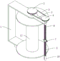
Fig. 1 is a first perspective view of a winding drum for textile machinery, which is convenient for yarn clamping and provided by the utility model;
FIG. 2 is a second perspective view of the winding drum for textile machinery, which is convenient for yarn clamping of the present invention;
FIG. 3 is a front view of a winding drum for textile machinery, which facilitates the yarn clamping of the utility model;
fig. 4 is an enlarged view of a portion a in fig. 2 of a winding drum for textile machinery convenient for yarn clamping according to the present invention.
In the figure: support frame 1, first belt pulley 2, belt 3, second belt pulley 4, connecting plate 5, spacing hole 6, spacing ring 7, reciprocal screw thread 8, gag lever post 9, pivot 10, fixed column 11, reel 12, thread bush 13, connecting block 14.
Detailed Description
The technical solutions in the embodiments of the present invention will be described clearly and completely with reference to the accompanying drawings in the embodiments of the present invention, and it is obvious that the described embodiments are only some embodiments of the present invention, not all embodiments.
Example 1
Referring to fig. 1-4, a reel for textile machinery convenient to card line, including support frame 1, it is connected with reel 12 to rotate through the bearing on the support frame 1, the first belt pulley 2 of fixedly connected with in reel 12 upper end, fixedly connected with connecting plate 5 on the support frame 1, it is connected with pivot 10 to rotate through the bearing on the connecting plate 5, fixedly connected with second belt pulley 4 on the pivot 10, the cover is equipped with belt 3 between second belt pulley 4 and the first belt pulley 2, through first belt pulley 2, second belt pulley 4, the design of belt 3, so that when reel 12 rotates, drive pivot 10 and rotate.
The rotating shaft 10 is provided with a reciprocating thread 8, the reciprocating thread 8 is connected with a thread bush 13 through a thread, the thread bush 13 is fixedly connected with a limit ring 7, the limit ring 7 is provided with a limit mechanism, the lower end of the support frame 1 is fixedly connected with a fixed column 11, a bearing between the rotating shaft 10 and the connecting plate 5 is a thrust ball bearing, the support frame 1 is of a U-shaped structure, when the rotating shaft 10 rotates, the limit mechanism plays a limiting role on the thread bush 13, so that the thread bush 13 is ensured to move, meanwhile, the winding drum 12 rotates, the wire can be uniformly wound on the winding drum 12, the tightness during winding is ensured, the wire is clamped, and the condition that the wire is loosened during winding is prevented,
stop gear includes with connecting plate 5 on fixed connection's connecting block 14, spacing hole 6 has been seted up to connecting block 14, fixedly connected with gag lever post 9 on the connecting plate 5, gag lever post 9 can insert into spacing hole 6, plays spacing effect through gag lever post 9 and spacing hole 6 to thread bush 13, prevents that thread bush 13 from taking place to rotate.
When carrying out the during operation, insert the fixed column 11 in the fixed orifices on the spinning machine, fix the device, pass spacing ring 7 system with the line on reel 12, rotate through drive arrangement drive reel 12, under first belt pulley 2, second belt pulley 4, belt 3 effect, drive pivot 10 and rotate, thread bush 13 removes, and reel 12 rotates simultaneously, will make the even winding of line on reel 12.
Example 2
Referring to fig. 4, as another preferred embodiment of the present invention, on the basis of embodiment 1, the rubber layer is fixedly connected to the inner wall of the spacing ring 7, and through the design of the rubber layer, the wear of the wire in the spacing ring 7 during movement is reduced, and the occurrence of wear-out is prevented.
The above, only be the concrete implementation of the preferred embodiment of the present invention, but the protection scope of the present invention is not limited thereto, and any person skilled in the art is in the technical scope of the present invention, according to the technical solution of the present invention and the utility model, the concept of which is equivalent to replace or change, should be covered within the protection scope of the present invention.
Claims (5)
1. The winding drum convenient for yarn clamping for the textile machinery comprises a support frame (1) and is characterized in that a winding drum (12) is connected to the support frame (1) in a rotating mode through a bearing, a first belt pulley (2) is fixedly connected to the upper end of the winding drum (12), a connecting plate (5) is fixedly connected to the support frame (1), a rotating shaft (10) is connected to the connecting plate (5) in a rotating mode through the bearing, a second belt pulley (4) is fixedly connected to the rotating shaft (10), a belt (3) is sleeved between the second belt pulley (4) and the first belt pulley (2), reciprocating threads (8) are formed in the rotating shaft (10), threaded sleeves (13) are connected to the reciprocating threads (8) in a threaded mode, limiting rings (7) are fixedly connected to the threaded sleeves (13), and limiting mechanisms are arranged on the limiting rings (7), the lower end of the support frame (1) is fixedly connected with a fixing column (11).
2. The winding drum convenient for yarn clamping for textile machinery as claimed in claim 1, wherein the limiting mechanism comprises a connecting block (14) fixedly connected with the connecting plate (5), the connecting block (14) is provided with a limiting hole (6), a limiting rod (9) is fixedly connected with the connecting plate (5), and the limiting rod (9) can be inserted into the limiting hole (6).
3. The winding drum for textile machinery convenient for yarn clamping as claimed in claim 1, wherein a rubber layer is fixedly connected to the inner wall of the limiting ring (7).
4. A reel for textile machinery convenient for thread jamming according to claim 1, characterized in that the bearing between the rotating shaft (10) and the connecting plate (5) is a thrust ball bearing.
5. A spool for textile machinery convenient for thread jamming according to claim 1 wherein the support frame (1) is of U-shaped configuration.
Priority Applications (1)
| Application Number | Priority Date | Filing Date | Title |
|---|---|---|---|
| CN202023098243.3U CN214243248U (en) | 2020-12-21 | 2020-12-21 | Winding drum convenient for yarn clamping for textile machinery |
Applications Claiming Priority (1)
| Application Number | Priority Date | Filing Date | Title |
|---|---|---|---|
| CN202023098243.3U CN214243248U (en) | 2020-12-21 | 2020-12-21 | Winding drum convenient for yarn clamping for textile machinery |
Publications (1)
| Publication Number | Publication Date |
|---|---|
| CN214243248U true CN214243248U (en) | 2021-09-21 |
Family
ID=77740428
Family Applications (1)
| Application Number | Title | Priority Date | Filing Date |
|---|---|---|---|
| CN202023098243.3U Expired - Fee Related CN214243248U (en) | 2020-12-21 | 2020-12-21 | Winding drum convenient for yarn clamping for textile machinery |
Country Status (1)
| Country | Link |
|---|---|
| CN (1) | CN214243248U (en) |
-
2020
- 2020-12-21 CN CN202023098243.3U patent/CN214243248U/en not_active Expired - Fee Related
Similar Documents
| Publication | Publication Date | Title |
|---|---|---|
| CN210236741U (en) | Anti-twisting device in textile machinery | |
| CN214243248U (en) | Winding drum convenient for yarn clamping for textile machinery | |
| CN116265632A (en) | Manufacturing method and device of vinylon harness cord | |
| CN210763656U (en) | Colored fiber yarn guiding device for textile machinery | |
| CN112520507A (en) | Yarn frame of reeling machine | |
| CN105293176B (en) | One kind weaving spindle Winder | |
| CN209113230U (en) | A kind of textile machines Thread-feeding device | |
| CN208917378U (en) | Two-for-one twister | |
| CN212151183U (en) | Adjustable yarn stretching frame for winder | |
| CN111020754B (en) | Automatic centering yarn roller positioning device for twisting machine | |
| CN211846671U (en) | Tail yarn winding and positioning device for covering machine | |
| CN210366368U (en) | Bobbin structure for spinning | |
| CN210150507U (en) | Wire binding barrel for textile machinery | |
| CN209193261U (en) | A kind of winding mechanism of spinning frame | |
| CN217948370U (en) | Winding structure of spinning frame | |
| CN214527328U (en) | Spinning is evenly around establishing device | |
| CN220537203U (en) | Spinning machine convenient to adjust chemical fiber tension | |
| CN220664472U (en) | Spinning finishing device for textile machining | |
| CN210973385U (en) | Bobbin winder groove drum roller cleaning device | |
| CN221420215U (en) | Yarn rewinding machine with uniform winding | |
| CN216891390U (en) | Yarn twisting device | |
| CN218261316U (en) | Yarn guiding device for textile machine | |
| CN103981602B (en) | A kind of actively holding holds the rotary device improving yarn surface structure | |
| CN219859807U (en) | Spool supporting structure of parallel axis machine | |
| CN209779157U (en) | Spindle of high-speed braiding machine |
Legal Events
| Date | Code | Title | Description |
|---|---|---|---|
| GR01 | Patent grant | ||
| GR01 | Patent grant | ||
| CF01 | Termination of patent right due to non-payment of annual fee | ||
| CF01 | Termination of patent right due to non-payment of annual fee |
Granted publication date: 20210921 |