CN214171831U - Paperless conference system management equipment - Google Patents
Paperless conference system management equipment Download PDFInfo
- Publication number
- CN214171831U CN214171831U CN202023070985.5U CN202023070985U CN214171831U CN 214171831 U CN214171831 U CN 214171831U CN 202023070985 U CN202023070985 U CN 202023070985U CN 214171831 U CN214171831 U CN 214171831U
- Authority
- CN
- China
- Prior art keywords
- bevel gear
- groove
- system management
- wall
- base
- Prior art date
- Legal status (The legal status is an assumption and is not a legal conclusion. Google has not performed a legal analysis and makes no representation as to the accuracy of the status listed.)
- Active
Links
Images


Abstract
The utility model discloses a paperless conference system management equipment, the on-line screen storage device comprises a base, the up end of base is provided with the recess, the rear fixed mounting of recess inner wall up end has the motor, the output fixedly connected with minor axis of motor, the surface cover of minor axis is equipped with bevel gear B, the inside of base articulates through the pivot has the rotor plate, the rear cover of pivot surface is equipped with bevel gear A, just bevel gear A with bevel gear B meshes, movable groove has all been seted up to the both sides of base inner wall, the both sides fixed mounting of rotor plate surface has the backup pad, the up end and the lower terminal surface of backup pad all are provided with the spout, the inboard sliding connection of spout has scalable loop bar, the other end of scalable loop bar with the inner wall fixed connection in movable groove. The utility model discloses can height-adjusting, improve the suitability, and be convenient for freely adjust the angle of display screen, improve user experience and feel.
Description
Technical Field
The utility model relates to a paperless meeting technical field specifically is a paperless meeting system management equipment.
Background
With the rapid development of social economy, the working meeting is more and more convenient, the paperless meeting is a new concept of an interactive system which is provided on the basis of research, development and construction of the traditional meeting and is a paperless meeting interactive system based on the mobile internet, the concept is provided and implemented to convert the traditional paper serving as an information recording carrier into digital and mobile multimedia taking a tablet personal computer and a smart phone as carriers, and the meeting is extended to an off-site mobile terminal from a fixed meeting room by utilizing the portability of the smart phone.
However, the existing paperless conference system is inconvenient to adjust the height of conference equipment during a conference, and the angles of most display screens cannot be freely adjusted, so that the user experience is poor; therefore, the existing requirements are not met, and a paperless conference system management device is provided for the requirements.
SUMMERY OF THE UTILITY MODEL
An object of the utility model is to provide a paperless meeting system management equipment to current paperless meeting system who proposes in solving above-mentioned background is inconvenient highly adjusting meeting equipment when carrying out the meeting, and most of display screen angles can not freely adjust, the relatively poor scheduling problem of user experience.
In order to achieve the above object, the utility model provides a following technical scheme: a paperless conference system management device comprises a base, wherein a groove is formed in the upper end face of the base, a motor is fixedly mounted behind the upper end face of the inner wall of the groove, a short shaft is fixedly connected to the output end of the motor, a bevel gear B is sleeved on the outer surface of the short shaft, a rotating plate is hinged inside the base through a rotating shaft, a bevel gear A is sleeved behind the outer surface of the rotating shaft and meshed with the bevel gear B, movable grooves are formed in two sides of the inner wall of the base, supporting plates are fixedly mounted on two sides of the outer surface of the rotating plate, sliding grooves are formed in the upper end face and the lower end face of each supporting plate, a telescopic loop bar is slidably connected to the inner side of each sliding groove, the other end of each telescopic loop bar is fixedly connected with the inner wall of each movable groove, a display screen is fixedly mounted on the upper end face of each rotating plate, and a camera is fixedly mounted behind the upper end face of each display screen, the utility model discloses a safety protection device for a motor vehicle, including base, the equal fixed mounting in place ahead and the rear of terminal surface has the montant under the base, the top of montant surface evenly is provided with four gear holes, the surface mounting of montant bottom has the gyro wheel, the surface mounting of gyro wheel frame has the gyro wheel, the lower terminal surface cover of montant is equipped with the outer tube, the top of outer tube surface is provided with the pinhole, the inboard of pinhole is provided with the round pin post, the round pin post runs through pinhole and one of them gear hole, the below fixedly connected with support column of outer tube, the outside of support column is provided with the bottom plate, run through being equipped with two logical grooves around the bottom plate up end, the lower terminal surface of support column is provided with square groove, the top surface fixed mounting of square inslot wall has electric putter, electric putter's lower terminal surface fixed mounting has the universal wheel.
Preferably, the lower end face of the bottom plate is fixedly connected with a rubber non-slip mat through a clamping groove, and the outer surface of the supporting column is fixedly connected with the inner wall of the through groove.
Preferably, a storage battery is arranged in the bottom plate, and the storage battery is electrically connected with the electric push rod.
Preferably, the telescopic sleeve rod comprises a thick sleeve and a thin sleeve rod, and the thin sleeve rod is clamped into the inner side of the thick sleeve.
Preferably, the outer surface of the roller carrier is provided with a strip-shaped groove, and the roller is connected with the strip-shaped groove through a connecting shaft.
Preferably, two ends of the rotating shaft are rotatably connected with the inner wall of the groove through bearings.
Preferably, the outer surface of the short shaft is fixedly connected with the inner ring of the bevel gear B through welding, and the outer surface of the rotating shaft is fixedly connected with the inner ring of the bevel gear A through welding.
Compared with the prior art, the beneficial effects of the utility model are that:
1. the utility model is provided with a bottom plate, a support column, a square groove, an electric push rod and a universal wheel, when the device needs to be moved, the switch of the electric push rod is opened, the electric push rod extends to drive the universal wheel to move downwards until the universal wheel contacts the ground, the lower end surface of the bottom plate leaves the ground, the switch of the electric push rod is closed, after the electric push rod moves to a proper position, the switch of the electric push rod is opened again, the electric push rod contracts to drive the universal wheel to move upwards until the universal wheel retracts into the inner side of the square groove, the lower end surface of the bottom plate contacts with the ground, the placement is stable, when the height of a display screen needs to be changed, the pin is pulled out, the vertical rod is adjusted to a proper height, the pin is inserted again, the pin passes through the pin hole and one of the proper gear holes, the utility model can adjust the height, the applicability is improved;
2. the utility model discloses a be provided with the rotor plate, bevel gear A, the apparatus further comprises a rotating shaft, bevel gear B, the minor axis, including a motor, an end cap, a controller, and a cover plate, when the angle of display screen needs to be adjusted, open the switch of motor, motor work drives the minor axis and changes the shelves, the minor axis rotates and drives bevel gear B and rotate, bevel gear A rotates, it rotates to drive the pivot, it is rotatory to drive the rotor plate, and then adjust the angle to the display screen, after adjusting suitable angle, close the switch of motor, through being provided with scalable loop bar, the spout, the backup pad, the rotatory stability of rotor plate has been improved, the utility model discloses be convenient for freely adjust the angle of display screen, user experience sense has been improved.
Drawings
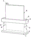
Fig. 1 is a schematic overall structure diagram of the present invention;
FIG. 2 is a side cross-sectional view of the present invention in its entirety;
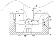
FIG. 3 is a schematic view of a partial structure of the base of the present invention;
fig. 4 is a schematic view of a partial structure of the support column of the present invention.
In the figure: 1. a base plate; 2. an outer sleeve; 3. a vertical rod; 4. a base; 5. a groove; 6. a display screen; 7. a camera; 8. a gear hole; 9. a pin; 10. a chute; 11. a rotating plate; 12. a bevel gear A; 13. a rotating shaft; 14. a telescopic loop bar; 15. a bevel gear B; 16. a minor axis; 17. a motor; 18. a support pillar; 19. a square groove; 20. a roller frame; 21. a roller; 22. a pin hole; 23. a through groove; 24. an electric push rod; 25. a universal wheel; 26. a support plate; 27. a movable groove.
Detailed Description
The technical solutions in the embodiments of the present invention will be described clearly and completely with reference to the accompanying drawings in the embodiments of the present invention, and it is obvious that the described embodiments are only some embodiments of the present invention, not all embodiments.
Referring to fig. 1 to 4, the present invention provides an embodiment: a paperless conference system management device comprises a base 4, a groove 5 is arranged on the upper end face of the base 4, a motor 17 is fixedly arranged behind the upper end face of the inner wall of the groove 5, an output end of the motor 17 is fixedly connected with a short shaft 16, a bevel gear B15 is sleeved on the outer surface of the short shaft 16, a rotating plate 11 is hinged inside the base 4 through a rotating shaft 13, a bevel gear A12 is sleeved behind the outer surface of the rotating shaft 13, a bevel gear A12 is meshed with the bevel gear B15, movable grooves 27 are formed in two sides of the inner wall of the base 4, supporting plates 26 are fixedly arranged on two sides of the outer surface of the rotating plate 11, sliding grooves 10 are formed in the upper end face and the lower end face of each supporting plate 26, a telescopic loop bar 14 is slidably connected to the inner side of each sliding groove 10, the other end of each telescopic loop bar 14 is fixedly connected with the inner wall of each movable groove 27, a display screen 6 is fixedly arranged on the upper end face of the rotating plate 11, and a camera 7 is fixedly arranged behind the upper end face of the display screen 6, the equal fixed mounting in place ahead and the rear of terminal surface has montant 3 under base 4, the top of 3 surfaces of montant evenly is provided with four gear holes 8, the surface mounting of 3 bottoms of montant has gyro wheel frame 20, the surface mounting of gyro wheel frame 20 has gyro wheel 21, the lower terminal surface cover of montant 3 is equipped with outer tube 2, the top of 2 surfaces of outer tube is provided with pinhole 22, the inboard of pinhole 22 is provided with round pin post 9, round pin post 9 runs through pinhole 22 and one of them gear hole 8, the below fixedly connected with support column 18 of outer tube 2, the outside of support column 18 is provided with bottom plate 1, run through around the 1 up end of bottom plate and be equipped with two logical grooves 23, the lower terminal surface of support column 18 is provided with square groove 19, the top surface fixed mounting of square groove 19 inner wall has electric putter 24, electric putter 24's lower terminal surface fixed mounting has universal wheel 25. Wherein, the motor 17 (the model can be YS7134), the electric push rod 24 (the model can be LBP40) mentioned in the utility model can all be obtained from market purchase or private customization.
Further, the lower terminal surface of bottom plate 1 passes through draw-in groove fixedly connected with rubber slipmat, the surface of support column 18 and the inner wall fixed connection who leads to groove 23.
Through adopting above-mentioned technical scheme, improve bottom plate 1's stability, improve the stability of connecting.
Further, a storage battery is arranged inside the bottom plate 1 and is electrically connected with the electric push rod 24.
By adopting the technical scheme, the electric push rod 24 can work under the condition that the power supply is not switched on.
Further, the telescopic rod 14 includes a thick sleeve and a thin rod, and the thin rod is snapped into the inside of the thick sleeve.
By adopting the technical scheme, the connection stability is improved.
Further, the outer surface of the roller frame 20 is provided with a strip-shaped groove, and the roller 21 is connected with the strip-shaped groove through a connecting shaft.
By adopting the technical scheme, the connection stability is improved.
Further, both ends of the rotating shaft 13 are rotatably connected with the inner wall of the groove 5 through bearings.
Through adopting above-mentioned technical scheme, improve pivot 13 pivoted stability.
Further, the outer surface of the stub shaft 16 is fixedly connected with the inner race of the bevel gear B15 by welding, and the outer surface of the rotating shaft 13 is fixedly connected with the inner race of the bevel gear a12 by welding.
By adopting the technical scheme, the stability of the bevel gear B15 and the bevel gear A12 is improved.
The working principle is as follows: when the device is used, when the device needs to be moved, the switch of the electric push rod 24 is turned on, the electric push rod 24 extends to drive the universal wheel 25 to move downwards until the universal wheel 25 contacts the ground, the lower end face of the bottom plate 1 leaves the ground, the switch of the electric push rod 24 is turned off, after the device moves to a proper position, the switch of the electric push rod 24 is turned on, the electric push rod 24 contracts to drive the universal wheel 25 to move upwards until the universal wheel 25 retracts into the inner side of the square groove 19, the lower end face of the bottom plate 1 contacts the ground, the device is placed stably, a power supply is switched on, when the height of the display screen 6 needs to be changed, the pin 9 is pulled out, the vertical rod 3 is adjusted to a proper height, the pin 9 is inserted, the pin 9 penetrates through the pin hole 22 and one proper gear hole 8, when the angle of the display screen 6 needs to be adjusted, the switch of the motor 17 is turned on, the motor 17, minor axis 16 rotates and drives bevel gear B15 and rotates, bevel gear A12 rotates, it rotates to drive pivot 13, it is rotatory to drive rotor plate 11, and then adjust the angle of display screen 6, adjust to suitable angle after, close motor 17's switch, through being provided with scalable loop bar 14, spout 10, backup pad 26, the rotatory stability of rotor plate 11 has been improved, the utility model discloses can height-adjusting, the suitability has been improved, and be convenient for freely adjust the angle of display screen 6, the user experience sense has been improved.
It is obvious to a person skilled in the art that the invention is not restricted to details of the above-described exemplary embodiments, but that it can be implemented in other specific forms without departing from the spirit or essential characteristics of the invention. The present embodiments are therefore to be considered in all respects as illustrative and not restrictive, the scope of the invention being indicated by the appended claims rather than by the foregoing description, and all changes which come within the meaning and range of equivalency of the claims are therefore intended to be embraced therein. Any reference sign in a claim should not be construed as limiting the claim concerned.
Claims (7)
1. A paperless conference system management device, comprising a base (4), characterized in that: the upper end face of the base (4) is provided with a groove (5), a motor (17) is fixedly mounted at the rear part of the upper end face of the inner wall of the groove (5), an output end of the motor (17) is fixedly connected with a short shaft (16), a bevel gear B (15) is sleeved on the outer surface of the short shaft (16), a rotating plate (11) is hinged inside the base (4) through a rotating shaft (13), a bevel gear A (12) is sleeved at the rear part of the outer surface of the rotating shaft (13), the bevel gear A (12) is meshed with the bevel gear B (15), movable grooves (27) are formed in both sides of the inner wall of the base (4), supporting plates (26) are fixedly mounted on both sides of the outer surface of the rotating plate (11), sliding grooves (10) are formed in the upper end face and the lower end face of the supporting plates (26), and telescopic sleeve rods (14) are slidably connected to the inner sides of the sliding grooves (10), the other end of scalable loop bar (14) with the inner wall fixed connection of activity groove (27), the up end fixed mounting of rotor plate (11) has display screen (6), the rear fixed mounting of display screen (6) up end has camera (7), the equal fixed mounting in the place ahead and the rear of terminal surface has montant (3) under base (4), the top of montant (3) surface evenly is provided with four gear holes (8), the surface mounting of montant (3) bottom has gyro wheel frame (20), the surface mounting of gyro wheel frame (20) has gyro wheel (21), the lower terminal surface cover of montant (3) is equipped with outer tube (2), the top of outer tube (2) surface is provided with pinhole (22), the inboard of pinhole (22) is provided with pin post (9), pin post (9) run through pinhole (22) and one of them gear hole (8), the utility model discloses a motor vehicle outer tube (2) of using, including outer tube (2), the below fixedly connected with support column (18), the outside of support column (18) is provided with bottom plate (1), run through around bottom plate (1) up end and be equipped with two logical groove (23), the lower terminal surface of support column (18) is provided with square groove (19), the top surface fixed mounting of square groove (19) inner wall has electric putter (24), the lower terminal surface fixed mounting of electric putter (24) has universal wheel (25).
2. The paperless conference system management device according to claim 1, wherein: the lower end face of the bottom plate (1) is fixedly connected with a rubber non-slip mat through a clamping groove, and the outer surface of the supporting column (18) is fixedly connected with the inner wall of the through groove (23).
3. The paperless conference system management device according to claim 1, wherein: the storage battery is arranged in the bottom plate (1) and electrically connected with the electric push rod (24).
4. The paperless conference system management device according to claim 1, wherein: the telescopic loop bar (14) comprises a thick sleeve and a thin loop bar, and the thin loop bar is clamped into the inner side of the thick sleeve.
5. The paperless conference system management device according to claim 1, wherein: the outer surface of the roller carrier (20) is provided with a strip-shaped groove, and the rollers (21) are connected with the strip-shaped groove through connecting shafts.
6. The paperless conference system management device according to claim 1, wherein: and the two ends of the rotating shaft (13) are rotatably connected with the inner wall of the groove (5) through bearings.
7. The paperless conference system management device according to claim 1, wherein: the outer surface of the short shaft (16) is fixedly connected with the inner ring of the bevel gear B (15) through welding, and the outer surface of the rotating shaft (13) is fixedly connected with the inner ring of the bevel gear A (12) through welding.
Priority Applications (1)
| Application Number | Priority Date | Filing Date | Title |
|---|---|---|---|
| CN202023070985.5U CN214171831U (en) | 2020-12-18 | 2020-12-18 | Paperless conference system management equipment |
Applications Claiming Priority (1)
| Application Number | Priority Date | Filing Date | Title |
|---|---|---|---|
| CN202023070985.5U CN214171831U (en) | 2020-12-18 | 2020-12-18 | Paperless conference system management equipment |
Publications (1)
| Publication Number | Publication Date |
|---|---|
| CN214171831U true CN214171831U (en) | 2021-09-10 |
Family
ID=77606920
Family Applications (1)
| Application Number | Title | Priority Date | Filing Date |
|---|---|---|---|
| CN202023070985.5U Active CN214171831U (en) | 2020-12-18 | 2020-12-18 | Paperless conference system management equipment |
Country Status (1)
| Country | Link |
|---|---|
| CN (1) | CN214171831U (en) |
-
2020
- 2020-12-18 CN CN202023070985.5U patent/CN214171831U/en active Active
Similar Documents
| Publication | Publication Date | Title |
|---|---|---|
| CN214171831U (en) | Paperless conference system management equipment | |
| CN211048853U (en) | Energy and power specialty teaching are with show board | |
| CN209803893U (en) | Self-service equipment for electric power marketing | |
| CN207281771U (en) | A kind of rotatable wireless charging scanner assemblies | |
| CN210493536U (en) | Marketing integrated service display device | |
| CN214796364U (en) | Portable display device is used in teaching | |
| CN214042997U (en) | Movable ideological and political education propaganda device | |
| CN210605592U (en) | Self-service marketing all-in-one | |
| CN212276594U (en) | Special multimedia teaching device of advertisement | |
| CN213215870U (en) | Chinese and English contrast look up learning device | |
| CN211336049U (en) | Medical computer shallow of clinical care that angularly adjustable and easily accomodate | |
| CN210672701U (en) | Multimedia equipment rack for education institution | |
| CN214376130U (en) | Dustproof computer display screen | |
| CN214744274U (en) | Graphic design and video editing art design terminal device | |
| CN205585589U (en) | Novel ideological and political education is explained device | |
| CN215125434U (en) | BIM-based management platform for PPP project | |
| CN211857838U (en) | Hypnosis teaching aid for psychological experiments | |
| CN216596863U (en) | Good exhibition frame of stability is used to business information consultation service | |
| CN214312562U (en) | Art education teaching display device | |
| CN215862695U (en) | Man-machine interaction all-in-one machine for image-text recognition | |
| CN216723640U (en) | Multifunctional office table | |
| CN213424242U (en) | Computer specialty is with study presentation device | |
| CN214587418U (en) | Practical training examination device for computer application | |
| CN214845828U (en) | Portable security inspection door | |
| CN212117485U (en) | Interactive workstation is used in business consultation |
Legal Events
| Date | Code | Title | Description |
|---|---|---|---|
| GR01 | Patent grant | ||
| GR01 | Patent grant |