CN214038367U - Power plant's boiler flue gas waste heat utilization system - Google Patents
Power plant's boiler flue gas waste heat utilization system Download PDFInfo
- Publication number
- CN214038367U CN214038367U CN202022938968.2U CN202022938968U CN214038367U CN 214038367 U CN214038367 U CN 214038367U CN 202022938968 U CN202022938968 U CN 202022938968U CN 214038367 U CN214038367 U CN 214038367U
- Authority
- CN
- China
- Prior art keywords
- heater
- pipe
- boiler
- level
- flue gas
- Prior art date
- Legal status (The legal status is an assumption and is not a legal conclusion. Google has not performed a legal analysis and makes no representation as to the accuracy of the status listed.)
- Active
Links
Images
Abstract
The utility model relates to a boiler flue gas utilizes technical field, provides a power plant's boiler flue gas waste heat utilization system, and it is equipped with the boiler, and the boiler is intake and is linked together through water supply line and boiler, is equipped with the tertiary low pressure feed water heater who heats in proper order on the water supply line, and tertiary low pressure feed water heater divide into first heater, second heater and the third heater that the temperature gradually rose, and the exhanst gas outlet of boiler is connected with dust remover, draught fan, desulfurization absorption tower and chimney in proper order through defeated tobacco pipe, the furnace of boiler be linked together with air preheater and heater through defeated tuber pipe in proper order, characterized in that defeated tobacco pipe on be equipped with one-level low temperature economizer and second grade low temperature economizer, have simple structure, convenient to use, waste heat utilization is effectual, waste heat utilization efficiency height advantage.
Description
Technical Field
The utility model belongs to the technical field of boiler flue gas utilization technique and specifically relates to a power plant boiler flue gas waste heat utilization system that simple structure, convenient to use, waste heat utilization are effectual, waste heat utilization efficiency is high.
Background
As is well known, in the thermal system of a thermal power plant, exhaust gas loss is the most important heat loss in the operation of a boiler, and the exhaust gas temperature of many boilers in the thermal power plant exceeds the designed value more. There is a large amount of calorific loss, in order to reduce the loss of discharging fume, reduces the exhaust gas temperature, and the energy saving improves the economic nature of power plant, consequently, needs carry out recycle to the boiler flue gas.
Disclosure of Invention
The utility model aims at solving the deficiencies of the prior art, providing a power boiler flue gas waste heat utilization system that simple structure, convenient to use, waste heat utilization are effectual, waste heat utilization efficiency is high.
The utility model provides a technical scheme that its technical problem adopted is:
the utility model provides a power plant's boiler flue gas waste heat utilization system, is equipped with the boiler, and the boiler is intake and is linked together through water supply pipe and boiler, is equipped with the tertiary low pressure heater who heats in proper order on the water supply pipe, and tertiary low pressure heater divide into first heater, second heater and the third heater that the temperature rises gradually, and the exhanst gas outlet of boiler is connected with dust remover, draught fan, desulfurization absorption tower and chimney through defeated tobacco pipe in proper order, the furnace of boiler be linked together with air preheater and air heater in proper order through defeated tuber pipe, its characterized in that defeated tobacco pipe on be equipped with one-level low temperature economizer and second grade low temperature economizer, one-level low temperature economizer establish on the defeated tobacco pipe between dust remover and exhanst gas outlet, the water inlet of one-level low temperature economizer be linked together through one-level inlet tube and first heater water inlet or delivery port, the one-level inlet tube on be equipped with the one-level circulating pump, the delivery port of one-level low temperature economizer advance the pipe with one-level outlet pipe and one-level water guide respectively through the tee bend and be linked together, the delivery port of one-level outlet pipe and second heater be linked together, the one-level water guide advances the pipe and is linked together with the air heater water inlet, the air heater delivery port is linked together through one-level water guide exit tube and one-level circulating pump water inlet, second grade low temperature economizer establish on the defeated tobacco pipe between draught fan and desulfurization absorption tower, the water inlet of second grade low temperature economizer be linked together through second grade inlet tube and air heater delivery port, the delivery port of second grade low temperature economizer is linked together through the water inlet of second grade outlet pipe and air heater, is equipped with the second grade circulating pump on the second grade outlet pipe, the work of one-level low temperature economizer and second grade low temperature economizer is realized to one-level circulating pump and second grade circulating pump.
Defeated tobacco pipe between the exhanst gas outlet of one-level low temperature economizer and boiler be connected with the gas inlet and the exhanst gas outlet of air preheater respectively, carry out preliminary cooling to the flue gas of boiler exhanst gas outlet through the air preheater.
One-level inlet tube, one-level outlet pipe, second grade inlet tube, second grade outlet pipe, one-level water guide advance and be equipped with the control valve on pipe and the one-level water guide exit tube respectively, through the work of control valve control one-level low temperature economizer and second grade low temperature economizer.
Import and the export of first heater be equipped with one-level inlet branch pipe respectively, one-level inlet branch pipe is linked together with the one-level inlet tube respectively, is equipped with the control valve on the one-level inlet branch pipe, the control valve control water is gone out water by the water inlet of first heater or the delivery port of first heater is gone out water.
The utility model discloses owing to adopt above-mentioned structure, have simple structure, convenient to use, waste heat utilization are effectual, waste heat utilization efficiency advantage such as high.
Drawings
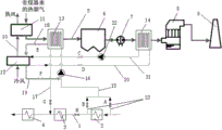
Fig. 1 is a schematic structural diagram of the present invention.
Detailed Description
The present invention will be further explained with reference to the accompanying drawings:
as shown in the attached drawing, the system for utilizing the waste heat of the boiler flue gas of the power plant is provided with a boiler, the boiler inlet water is communicated with the boiler through a water supply pipeline 1, a three-stage low-pressure heater which is sequentially heated is arranged on the water supply pipeline 1 and is divided into a first heater 2, a second heater 3 and a third heater 4, the temperature of the three-stage low-pressure heater is gradually increased, the flue gas outlet of the boiler is sequentially connected with a dust remover 6, an induced draft fan 7, a desulfurization absorption tower 8 and a chimney 9 through a flue gas transmission pipe 5, the hearth of the boiler is sequentially communicated with an air preheater 11 and a air heater 12 through an air transmission pipe 10, the system is characterized in that a first-stage low-temperature economizer 13 and a second-stage low-temperature economizer 14 are arranged on the flue gas transmission pipe 5 between the dust remover 6 and the flue gas outlet, the water inlet of the first-stage low-temperature economizer 13 is communicated with the water inlet or the water outlet of the first heater 2 through a first-stage water inlet pipe 15, a first-stage circulating pump 16 is arranged on the first-stage water inlet pipe 15, the water outlet of the first-stage low-temperature economizer 13 is respectively communicated with a first-stage water outlet pipe 17 and a first-stage water guide inlet pipe 18 through a tee joint, the primary water outlet pipe 17 is communicated with the water outlet of the second heater 3, the primary water guide inlet pipe 18 is communicated with the water inlet of the air heater 12, the water outlet of the air heater 12 is communicated with the water inlet of the primary circulating pump 16 through the primary water guide outlet pipe 19, the second-stage low-temperature economizer 14 is arranged on the smoke conveying pipe 5 between the induced draft fan 7 and the desulfurization absorption tower 8, the water inlet of the second-stage low-temperature economizer 14 is communicated with the water outlet of the air heater 12 through a second-stage water inlet pipe 20, the water outlet of the second-stage low-temperature economizer 14 is communicated with the water inlet of the air heater 12 through a second-stage water outlet pipe 21, a second-stage circulating pump 22 is arranged on the second-stage water outlet pipe 21, and the first-stage circulating pump 16 and the second-stage circulating pump 22 realize the work of the first-stage low-temperature economizer 13 and the second-stage low-temperature economizer 14.
Further, the smoke conveying pipe 5 between the primary low-temperature economizer 13 and the smoke outlet of the boiler is respectively connected with the smoke inlet and the smoke outlet of the air preheater 11, and the smoke at the smoke outlet of the boiler is primarily cooled through the air preheater 11.
Further, the primary water inlet pipe 15, the primary water outlet pipe 17, the secondary water inlet pipe 20, the secondary water outlet pipe 21, the primary water guide inlet pipe 18 and the primary water guide outlet pipe 19 are respectively provided with a control valve, and the work of the primary low-temperature economizer 13 and the secondary low-temperature economizer 14 is controlled by the control valves.
Further, the inlet and the outlet of the first heater 2 are respectively provided with a first-stage water inlet branch pipe 23, the first-stage water inlet branch pipes 23 are respectively communicated with the first-stage water inlet pipe 15, the first-stage water inlet branch pipes 23 are provided with control valves, and the control valves control water to be discharged from the water inlet of the first heater 2 or the water outlet of the first heater 2.
When the utility model is used, as shown in the figure, the control valves respectively arranged on the first-stage water inlet pipe 15, the first-stage water outlet pipe 17, the second-stage water inlet pipe 20, the second-stage water outlet pipe 21, the first-stage water inlet pipe 18 and the first-stage water outlet pipe 19 and the control valves arranged on the first-stage water inlet branch pipe 23 are respectively a control valve A, a control valve B, a control valve C, a control valve D, a control valve E, a control valve F and a control valve G, a control valve H is arranged between the first heater 2 and the second heater 3, the boiler inlet water can be heated by the smoke passing through the first-stage low-temperature economizer 13 by opening the control valve A or the control valve B, the control valve G and the first-stage circulating pump 16, the air inlet of the air heater 12 can be heated by the smoke of the second-stage low-temperature economizer 14 by opening the control valve C, the control valve E, the control valve F and the first-stage circulating pump 16, the air inlet of the air heater 12 can be heated by the smoke of the first-stage low-temperature economizer 13, the reasonable utilization of the waste heat of the flue gas is realized, when the temperature of the secondary low-temperature economizer 14 is lower than 70 ℃, the secondary low-temperature economizer 14 can be closed, the primary low-temperature economizer 13 is adopted to heat the air heater 12 at the moment, the flue gas is cooled, and the heat energy of the flue gas is utilized by opening and closing each valve.
Claims (4)
1. The utility model provides a power plant's boiler flue gas waste heat utilization system, is equipped with the boiler, and the boiler is intake and is linked together through water supply pipe and boiler, is equipped with the tertiary low pressure heater who heats in proper order on the water supply pipe, and tertiary low pressure heater divide into first heater, second heater and the third heater that the temperature rises gradually, and the exhanst gas outlet of boiler is connected with dust remover, draught fan, desulfurization absorption tower and chimney through defeated tobacco pipe in proper order, the furnace of boiler be linked together with air preheater and air heater in proper order through defeated tuber pipe, its characterized in that defeated tobacco pipe on be equipped with one-level low temperature economizer and second grade low temperature economizer, one-level low temperature economizer establish on the defeated tobacco pipe between dust remover and exhanst gas outlet, the water inlet of one-level low temperature economizer be linked together through one-level inlet tube and first heater water inlet or delivery port, the one-level inlet tube on be equipped with the one-level circulating pump, the delivery port of one-level low temperature economizer advance the pipe with one-level outlet pipe and one-level water guide respectively through the tee bend and be linked together, the delivery port of one-level outlet pipe and second heater be linked together, the one-level water guide advances the pipe and is linked together with the air heater water inlet, the air heater delivery port is linked together through one-level water guide exit tube and one-level circulating pump water inlet, second grade low temperature economizer establish on the defeated tobacco pipe between draught fan and desulfurization absorption tower, the water inlet of second grade low temperature economizer be linked together through second grade inlet tube and air heater delivery port, the delivery port of second grade low temperature economizer is linked together through the water inlet of second grade outlet pipe and air heater, is equipped with the second grade circulating pump on the second grade outlet pipe, the work of one-level low temperature economizer and second grade low temperature economizer is realized to one-level circulating pump and second grade circulating pump.
2. A power plant boiler flue gas waste heat utilization system according to claim 1, characterized in that a flue gas conveying pipe between the primary low-temperature economizer and the flue gas outlet of the boiler is respectively connected with a flue gas inlet and a flue gas outlet of an air preheater, and the flue gas at the flue gas outlet of the boiler is primarily cooled by the air preheater.
3. The power plant boiler flue gas waste heat utilization system according to claim 1, wherein the primary water inlet pipe, the primary water outlet pipe, the secondary water inlet pipe, the secondary water outlet pipe, the primary water inlet pipe and the primary water outlet pipe are respectively provided with a control valve, and the work of the primary low-temperature economizer and the work of the secondary low-temperature economizer are controlled by the control valves.
4. A power plant boiler flue gas waste heat utilization system according to claim 1, characterized in that the inlet and outlet of the first heater are respectively provided with a primary water inlet branch pipe, the primary water inlet branch pipes are respectively communicated with a primary water inlet pipe, the primary water inlet branch pipes are provided with control valves, and the control valves control water to be discharged from the water inlet of the first heater or the water outlet of the first heater.
Priority Applications (1)
| Application Number | Priority Date | Filing Date | Title |
|---|---|---|---|
| CN202022938968.2U CN214038367U (en) | 2020-12-10 | 2020-12-10 | Power plant's boiler flue gas waste heat utilization system |
Applications Claiming Priority (1)
| Application Number | Priority Date | Filing Date | Title |
|---|---|---|---|
| CN202022938968.2U CN214038367U (en) | 2020-12-10 | 2020-12-10 | Power plant's boiler flue gas waste heat utilization system |
Publications (1)
| Publication Number | Publication Date |
|---|---|
| CN214038367U true CN214038367U (en) | 2021-08-24 |
Family
ID=77334367
Family Applications (1)
| Application Number | Title | Priority Date | Filing Date |
|---|---|---|---|
| CN202022938968.2U Active CN214038367U (en) | 2020-12-10 | 2020-12-10 | Power plant's boiler flue gas waste heat utilization system |
Country Status (1)
| Country | Link |
|---|---|
| CN (1) | CN214038367U (en) |
-
2020
- 2020-12-10 CN CN202022938968.2U patent/CN214038367U/en active Active
Similar Documents
| Publication | Publication Date | Title |
|---|---|---|
| CN107120714B (en) | A kind of whole yearization comprehensive utilization energy conserving system | |
| CN102607010B (en) | Composite phase-change heat exchange system | |
| CN101173324A (en) | Novel technique for comprehensive utilization of continuous strip annealing furnace flue gas exhaust heat and device thereof | |
| CN107178814A (en) | A kind of thermal power plant boiler fume afterheat is used for the energy conserving system of central heating | |
| CN103244944A (en) | Air preheating system and method performing steam extraction by utilizing steam turbine | |
| CN206846764U (en) | A kind of coal-fired hot-water boiler fume afterheat depth recovery system | |
| CN104006401A (en) | Power station boiler smoke waste heat deep recycling and emission reducing system | |
| CN203249228U (en) | Air pre-heating system extracting steam through steam turbine | |
| CN206989172U (en) | The denitration of boiler full load couples fume afterheat gradient utilization system | |
| CN205690425U (en) | A kind of residual heat from boiler fume Multi-class propagation combines condensation water heating supply air system | |
| CN204693475U (en) | The novel anti-low-temperature corrosion waste-heat recovery device of the band adjustable boiler of power plant of temperature | |
| CN102494329B (en) | Device for utilizing flue gas waste heat of boiler comprehensively | |
| CN209445339U (en) | A kind of energy-saving and environment-friendly exhaust gas electricity generation boiler | |
| CN101928796A (en) | High wind temperature energy saving and emission reduction combined preheating method for blast furnace | |
| CN214038367U (en) | Power plant's boiler flue gas waste heat utilization system | |
| CN205048411U (en) | Gas boiler | |
| CN208735652U (en) | The eliminating white smoke system that a kind of heat exchanger and air preheater combine | |
| CN207262700U (en) | A kind of flue gas waste heat recovery water jacket furnace | |
| CN106439878A (en) | Flue gas waste heat utilizing system of condensed water heating boiler for air supply | |
| CN109506246A (en) | A kind of water-borne formula steam air heater of two-stage combined heat | |
| CN202660525U (en) | Composite phase-change heat exchange system | |
| CN211424362U (en) | Deaerator preheating system capable of improving steam output supplied from back pressure unit | |
| CN102012039B (en) | Forced circulation air preheat system | |
| CN201259210Y (en) | Non-phase-change composite heat exchanger | |
| CN112097287B (en) | Boiler energy-saving and flue gas whitening system, process and application |
Legal Events
| Date | Code | Title | Description |
|---|---|---|---|
| GR01 | Patent grant | ||
| GR01 | Patent grant |