CN214024804U - High-efficient refrigerated side milling numerical control planer-type milling machine - Google Patents
High-efficient refrigerated side milling numerical control planer-type milling machine Download PDFInfo
- Publication number
- CN214024804U CN214024804U CN202023163904.6U CN202023163904U CN214024804U CN 214024804 U CN214024804 U CN 214024804U CN 202023163904 U CN202023163904 U CN 202023163904U CN 214024804 U CN214024804 U CN 214024804U
- Authority
- CN
- China
- Prior art keywords
- operation platform
- numerical control
- groove
- milling
- milling machine
- Prior art date
- Legal status (The legal status is an assumption and is not a legal conclusion. Google has not performed a legal analysis and makes no representation as to the accuracy of the status listed.)
- Active
Links
Images


Abstract
The utility model relates to the field of numerical control planer type milling machine equipment, and discloses a high-efficiency cooling side milling numerical control planer type milling machine, which comprises a milling machine, wherein the milling machine comprises an operation platform, a liquid accumulation groove and two supports, the upper surfaces of the two supports are respectively fixedly connected with the front end and the rear end of the lower surface of the operation platform, the liquid accumulation groove is fixedly arranged at the middle part of the rear end of the upper surface of the operation platform, a liquid storage tank is arranged below the liquid accumulation groove, anti-overflow strips are fixedly arranged at the four edges of the upper surface of the operation platform, side milling equipment is arranged above the rear end of the upper surface of the operation platform, the lower surface of a vertical frame is fixedly connected with the left end and the right end of the rear end of the upper surface of the operation platform, a nozzle continuously sprays water to a processing part for cooling in the processing process, the chips generated in the processing process are washed along the strip, the influence of the high temperature of a workpiece and the chips on the processing quality is avoided, the water resource is saved, and the production is reduced, after the machined workpiece is machined, the machined workpiece can be collected and cleaned by operators, and the scraps can be collected and recycled.
Description
Technical Field
The utility model relates to a numerical control planer-type milling machine equipment field especially relates to a high-efficient refrigerated side milling numerical control planer-type milling machine.
Background
The milling machine is a milling machine with a portal frame and a horizontal long lathe bed. The planer type milling machine can simultaneously machine the surface by a plurality of milling cutters, has higher machining precision and production efficiency, and is suitable for machining planes and inclined planes of large-scale workpieces in batch and mass production. The numerical control planomiller can also process space curved surfaces and some special parts, the planomiller has the appearance similar to the planomiller, the difference is that the beam and the column of the planomiller are provided with a milling cutter frame with a main spindle box instead of a planer cutter frame, the reciprocating motion of the longitudinal workbench of the planomiller is not the main motion but the feed motion, and the rotary motion of the milling cutter is the main motion, the side milling head, the other name: the angle head is an accessory of a machine tool, and the rotation center line of a cutter can form an angle with the rotation center line of a main shaft to process a workpiece after the machine tool is provided with a milling head. Originally in Europe, the die is widely applied to various fields of machining of aviation, automobiles, dies and the like. The milling head is used, the processing range and the adaptability of the milling head can be increased without changing the structure of a machine tool, some processing which is difficult to complete by using a traditional method can be realized, repeated clamping of workpieces can be reduced, the processing precision and the processing efficiency are improved, sewage after being cooled by liquid spraying is directly discharged, the environment is polluted, the production consumption is large, therefore, the side milling numerical control planer type milling machine with efficient cooling is provided, the sewage with fragments after being washed is collected at the position of the filter block along the slope groove surface of the liquid accumulation groove, compared with a direct waste cooling mode after being cooled, the water resource is saved, the production consumption is reduced, the filtered fragments are stopped on the filter block for treatment, the processed workpieces can be collected and cleaned by operators, and the fragments can be collected and recovered.
SUMMERY OF THE UTILITY MODEL
The utility model mainly solves the technical problem existing in the prior art and provides a high-efficiency cooling side milling numerical control planer type milling machine.
In order to realize the above-mentioned purpose, the utility model discloses a following technical scheme, a high-efficient refrigerated side milling numerical control planer-type milling machine, including milling machine, milling machine includes operation platform, ponding groove and support, the support is totally two both ends fixed connection around the upper surface of support respectively with operation platform's lower surface, the fixed mid portion that sets up at operation platform's upper surface rear end of ponding groove, the below in ponding groove is provided with the liquid reserve tank, operation platform's upper surface four borders is all fixed and is provided with the anti-overflow strip, operation platform's upper surface rear end top is provided with side milling equipment, side milling equipment includes grudging post, milling head and movable rod, both ends fixed connection about the lower surface of grudging post and operation platform's upper surface rear end.
Preferably, the middle parts of the upper surface and the lower surface of the liquid collecting tank are provided with inclined circular grooves, filter blocks are arranged in the inclined circular grooves, the lower ends of the inclined circular grooves are provided with circular pipes, the upper surfaces of the circular pipes are fixedly connected with the lower notch of the inclined circular grooves, and the lower surfaces of the circular pipes are fixedly connected with the middle parts of the upper surfaces of the liquid storage tanks.
Preferably, the middle parts of the two opposite surfaces of the lower end of the vertical frame are provided with sliding grooves, the middle part of the upper surface of the vertical frame is provided with a rod groove, the movable rod is movably sleeved with the rod groove, and the lower end of the movable rod is provided with a milling head.
Preferably, the middle part of the upper surface of the milling head is fixedly connected with the lower end of the movable rod, the middle part of the upper surface of the movable rod and the front end of the lower end of the rod surface are both provided with a pipe groove, and a nozzle is fixedly arranged on the notch of the pipe groove at the lower end.
Preferably, the left surface and the right surface of the milling head are both provided with connecting blocks, two opposite surfaces of the two connecting blocks are respectively and fixedly connected with the middle part of the left surface and the right surface of the milling head, and two separated ends of the two connecting blocks are respectively and movably arranged in the two sliding grooves.
Preferably, the pipe groove at the upper end is provided with a water pipe, and the lower end of the water pipe is communicated with the bottom of the liquid storage tank.
Advantageous effects
The utility model provides a high-efficient refrigerated side milling numerical control planer-type milling machine. The method has the following beneficial effects:
(1) this high-efficient refrigerated side mills numerical control planer-type milling machine, operating personnel places the machined part and processes through the cutter head on operation platform, the spout constantly cools down to the processing position water spray in the course of working, in the same direction as the area erodees the piece that produces in the course of working, avoid machined part high temperature and piece to produce the influence to processingquality, the clastic sewage of taking after the washing away collects in filter block department along the slope groove face in ponding groove, compare the direct discarded cooling mode after the cooling, save the water resource and reduce the production consumption.
(2) This high-efficient refrigerated side mills numerical control planer-type milling machine, the piece that filters down stops on the filter block pending, can collect the clearance by operating personnel after having processed the machined part, can collect the recovery to the piece.
Drawings
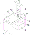
FIG. 1 is a schematic view of the overall structure of the high-efficiency cooling side milling numerical control planer type milling machine of the present invention;
FIG. 2 is a schematic structural view of the milling machine of FIG. 1 according to the present invention;
FIG. 3 is a schematic structural view of the side milling apparatus of FIG. 1 according to the present invention;
fig. 4 is an enlarged schematic view of a portion a in fig. 3 according to the present invention.
Illustration of the drawings:
1. milling machine; 2. side milling equipment; 11. an operating platform; 12. an anti-overflow strip; 13. a liquid accumulation tank; 14. a filter block; 15. an oblique circular groove; 16. a liquid storage tank; 17. a support; 18. a circular tube; 21. erecting a frame; 22. connecting blocks; 23. a chute; 24. a rod groove; 25. a movable rod; 26. a water pipe; 27. a milling head; 28. a spout; 29. and (4) a pipe groove.
Detailed Description
The technical solution of the present invention is further specifically described below by way of examples and with reference to the accompanying drawings.
Example (b): a high-efficiency cooling numerical control planomiller for side milling comprises a miller 1, wherein the miller 1 comprises an operation platform 11, liquid accumulation grooves 13 and two supports 17, the two supports 17 are respectively fixedly connected with the front end and the rear end of the lower surface of the operation platform 11, the liquid accumulation grooves 13 are fixedly arranged at the middle part of the rear end of the upper surface of the operation platform 11, a liquid storage tank 16 is arranged below the liquid accumulation grooves 13, anti-overflow strips 12 are fixedly arranged at the four edges of the upper surface of the operation platform 11, a side milling device 2 is arranged above the rear end of the upper surface of the operation platform 11, the side milling device 2 comprises a vertical frame 21, a milling head 27 and a movable rod 25, the lower surface of the vertical frame 21 is fixedly connected with the left end and the right end of the rear end of the upper surface of the operation platform 11, the middle part of the upper surface and the lower surface of the liquid accumulation grooves 13 is provided with inclined circular grooves 15, filter blocks 14 are arranged in the inclined circular grooves 15, the lower end of the inclined circular groove 15 is provided with a circular pipe 18, the upper surface of the circular pipe 18 is fixedly connected with the lower notch of the inclined circular groove 15, the lower surface of the circular pipe 18 is fixedly connected with the middle part of the upper surface of the liquid storage box 16, the middle parts of two opposite surfaces of the lower end of the vertical frame 21 are respectively provided with a sliding groove 23, the middle part of the upper surface of the vertical frame 21 is respectively provided with a rod groove 24, a movable rod 25 is movably sleeved with the rod groove 24, the lower end of the movable rod 25 is provided with a milling head 27, the middle part of the upper surface of the milling head 27 is fixedly connected with the lower end of the movable rod 25, the middle part of the upper surface of the movable rod 25 and the front end of the lower end of the rod surface are respectively provided with a pipe groove 29, the notch of the pipe groove 29 at the lower end is fixedly provided with a nozzle 28, the left surface and the right surface of the milling head 27 are respectively provided with connecting blocks 22, the opposite two opposite surfaces of the two connecting blocks 22 are respectively fixedly connected with the middle parts of the left surface and the right surface of the milling head 27, the two separating ends are respectively and movably arranged in the two sliding grooves 23, an operator places a machined part on the operation platform 11 to be machined through the milling head 27, the nozzle 28 continuously sprays water to a machined part to cool down in the machining process, scraps generated in the machining process are washed along the belt, the influence of high temperature of the machined part and the scraps on the machining quality is avoided, the washed sewage with the scraps is collected at the filter block 14 along the slope groove surface of the liquid collecting groove 13, liquid slides down to the liquid storage tank 16 along the circular pipe 18 through the filtration of the filter block 14, the filtered scraps stay on the filter block 14 to be treated, the machined part can be collected and cleaned by the operator after being machined, the liquid in the liquid storage tank 16 can be sprayed and cooled through the nozzle 26 again after being purified by internal purifying equipment, compared with a direct waste cooling mode after cooling, the water resource is saved, the production consumption is reduced, and meanwhile the scraps can be collected and recovered, the pipe groove 29 at the upper end is provided with a water pipe 26, and the lower end of the water pipe 26 is communicated with the bottom of the liquid storage tank 16.
The utility model discloses a theory of operation:
when in use, an operator places a workpiece on the operation platform 11 to process the workpiece through the milling head 27, the nozzle 28 continuously sprays water to the processing part to cool the processing part in the processing process, the chips generated in the processing process are washed along the belt, the influence of the high temperature of the workpiece and the chips on the processing quality is avoided, the washed sewage with the chips is collected at the filter block 14 along the slope groove surface of the liquid collecting groove 13, through the filtration of filter block 14, liquid is in the same direction as in pipe 18 gliding to liquid reserve tank 16, the piece that filters down stops pending on filter block 14, the clearance can be collected by operating personnel after having processed the machined part, liquid in the liquid reserve tank 16 can be used for spout 28 to spray the cooling through water pipe 26 once more after inside clarification plant purification treatment, compare the direct discarded cooling mode after the cooling, save water resource reduction production consumption, can collect the recovery to the piece simultaneously.
Finally, it should be noted that the above embodiments are merely representative examples of the present invention. Obviously, the present invention is not limited to the above-described embodiments, and many modifications are possible. Any simple modification, equivalent change and modification made to the above embodiments according to the technical spirit of the present invention should be considered as belonging to the protection scope of the present invention.
Claims (6)
1. The utility model provides a high-efficient refrigerated side milling numerical control planer-type milling machine, includes milling machine (1), its characterized in that: milling machine (1) is including operation platform (11), hydrops groove (13) and support (17), support (17) are two altogether, two the upper surface of support (17) respectively with operation platform (11) lower surface front and back both ends fixed connection, the fixed mid portion that sets up at the upper surface rear end of operation platform (11) in hydrops groove (13), the below of hydrops groove (13) is provided with liquid reserve tank (16), four borders of upper surface of operation platform (11) are all fixed anti-overflow strip (12) of being provided with, the upper surface rear end top of operation platform (11) is provided with side milling equipment (2), side milling equipment (2) are including grudging post (21), milling head (27) and movable rod (25), both ends fixed connection about the lower surface of grudging post (21) and the upper surface rear end of operation platform (11).
2. The high-efficiency cooling side milling numerical control planomiller according to claim 1, characterized in that: oblique circular slot (15) have been seted up to the upper and lower face mid portion of hydrops groove (13), be provided with filter block (14) in oblique circular slot (15), oblique circular slot (15) lower extreme is provided with pipe (18), the upper surface of pipe (18) and the lower notch fixed connection of oblique circular slot (15), the lower surface of pipe (18) and the upper surface mid portion fixed connection of liquid reserve tank (16).
3. The high-efficiency cooling side milling numerical control planomiller according to claim 1, characterized in that: the middle part of the two opposite sides of lower extreme of grudging post (21) has all seted up spout (23), the intermediate portion of the upper surface of grudging post (21) separately is equipped with pole groove (24), movable rod (25) and pole groove (24) activity cup joint, the lower extreme of movable rod (25) is provided with cutter head (27).
4. The high-efficiency cooling side milling numerical control planomiller according to claim 3, characterized in that: the middle part of the upper surface of the milling head (27) is fixedly connected with the lower end of the movable rod (25), the middle part of the upper surface of the movable rod (25) and the front end of the lower end of the rod surface are both provided with a pipe groove (29), and a nozzle (28) is fixedly arranged at the notch of the pipe groove (29) at the lower end.
5. The high-efficiency cooling side milling numerical control planomiller according to claim 3, characterized in that: the face all is provided with connecting block (22) about cutter head (27), two the relative two sides of connecting block (22) respectively with cutter head (27) about face mid portion fixed connection, two the both ends that separate of connecting block (22) are the activity respectively and are set up in two spout (23).
6. The high-efficiency cooling side milling numerical control planomiller according to claim 4, characterized in that: the pipe groove (29) at the upper end is provided with a water pipe (26), and the lower end of the water pipe (26) is communicated with the bottom of the liquid storage tank (16).
Priority Applications (1)
| Application Number | Priority Date | Filing Date | Title |
|---|---|---|---|
| CN202023163904.6U CN214024804U (en) | 2020-12-24 | 2020-12-24 | High-efficient refrigerated side milling numerical control planer-type milling machine |
Applications Claiming Priority (1)
| Application Number | Priority Date | Filing Date | Title |
|---|---|---|---|
| CN202023163904.6U CN214024804U (en) | 2020-12-24 | 2020-12-24 | High-efficient refrigerated side milling numerical control planer-type milling machine |
Publications (1)
| Publication Number | Publication Date |
|---|---|
| CN214024804U true CN214024804U (en) | 2021-08-24 |
Family
ID=77341932
Family Applications (1)
| Application Number | Title | Priority Date | Filing Date |
|---|---|---|---|
| CN202023163904.6U Active CN214024804U (en) | 2020-12-24 | 2020-12-24 | High-efficient refrigerated side milling numerical control planer-type milling machine |
Country Status (1)
| Country | Link |
|---|---|
| CN (1) | CN214024804U (en) |
-
2020
- 2020-12-24 CN CN202023163904.6U patent/CN214024804U/en active Active
Similar Documents
| Publication | Publication Date | Title |
|---|---|---|
| CN108098356B (en) | Milling and grinding machining center | |
| CN104759667B (en) | A kind of two-sided CNC milling machine | |
| CN107984290B (en) | A high ray apparatus of numerical control for machine-building | |
| CN112207312A (en) | Drilling machine capable of recycling cooling liquid | |
| CN112388332B (en) | Turning, grinding and milling combined machine tool | |
| CN213163259U (en) | A milling machine for speed reducer production | |
| CN214024804U (en) | High-efficient refrigerated side milling numerical control planer-type milling machine | |
| CN211889153U (en) | Carving mills waste material processing structure of machine | |
| CN108655816A (en) | A kind of small size lathe with cooling effect | |
| CN110000630B (en) | Numerical control knife sharpener | |
| CN216461763U (en) | Novel numerical control lathe | |
| CN210231652U (en) | Numerical control planer-type milling machine convenient to it is clean | |
| CN205927177U (en) | Automatic change and mill boring machining device | |
| CN210649498U (en) | Cutting machine tool convenient for fixing cutting object | |
| CN109823102B (en) | High-precision graphite engraving and milling machine with automatic waste recycling function | |
| CN217572077U (en) | Gantry type boring and milling machining center | |
| CN205571921U (en) | A workstation for machining center | |
| CN112223611A (en) | Finish machining treatment machine for production and manufacturing of glass fiber reinforced plastic grating plate | |
| CN220783181U (en) | Numerical control turning and boring combined machining tool | |
| CN219402499U (en) | Five-axis precise numerical control planer type milling machine | |
| CN220592444U (en) | Cooling device for machining automobile parts | |
| CN218746120U (en) | Numerical control gantry boring and milling machine with cooling device | |
| CN219131002U (en) | A high-efficient processingequipment for steel bar cutting | |
| CN215786956U (en) | Light planer-type milling machine of base self-cleaning formula | |
| CN217596618U (en) | Cylindrical grinder with efficient cooling function for manufacturing metal products |
Legal Events
| Date | Code | Title | Description |
|---|---|---|---|
| GR01 | Patent grant | ||
| GR01 | Patent grant |