CN213970313U - High-precision horizontal-shaft circular-table surface grinding machine - Google Patents
High-precision horizontal-shaft circular-table surface grinding machine Download PDFInfo
- Publication number
- CN213970313U CN213970313U CN202022153248.5U CN202022153248U CN213970313U CN 213970313 U CN213970313 U CN 213970313U CN 202022153248 U CN202022153248 U CN 202022153248U CN 213970313 U CN213970313 U CN 213970313U
- Authority
- CN
- China
- Prior art keywords
- vertical
- horizontal
- transverse
- motor
- slide
- Prior art date
- Legal status (The legal status is an assumption and is not a legal conclusion. Google has not performed a legal analysis and makes no representation as to the accuracy of the status listed.)
- Active
Links
Images


Landscapes
- Finish Polishing, Edge Sharpening, And Grinding By Specific Grinding Devices (AREA)
Abstract
The utility model discloses a high accuracy horizontal axis round platform flat grinder, include: the fuselage the upper end of fuselage is provided with horizontal slide rail slide on the horizontal slide rail and be provided with horizontal slide the upper end of fuselage is provided with horizontal ball vice, horizontal ball is vice to be connected with transverse driving device, horizontal slide is connected with horizontal ball vice through horizontal flexible coupling device the lower extreme of horizontal slide is provided with vertical slide rail slide on the vertical slide rail and be provided with vertical slide the lower extreme of horizontal slide is provided with vertical ball vice, vertical ball is vice to be connected with vertical drive arrangement, vertical slide is connected with vertical ball vice through vertical flexible coupling device vertical cylinder is provided with on the vertical slide.
Description
Technical Field
The utility model relates to a grinding machine especially relates to a high accuracy horizontal axis round platform surface grinder.
Background
The existing high-precision horizontal-axis circular truncated cone surface grinding machine can only turn over a workpiece manually when the workpiece is machined, and because the quality of some workpieces is large, if the workpiece is turned over manually, the problems of high labor intensity, low working efficiency and the like exist, and how to design the high-precision horizontal-axis circular truncated cone surface grinding machine capable of achieving automatic turning becomes a problem which needs to be solved urgently by people.
SUMMERY OF THE UTILITY MODEL
The utility model discloses the technical problem that will solve is: the high-precision horizontal-shaft circular-table surface grinding machine is high in working efficiency.
In order to solve the technical problem, the utility model discloses a technical scheme is: high accuracy horizontal axis round platform flat grinder includes: the machine body, be provided with horizontal slide rail in the upper end of fuselage, slide on the horizontal slide rail and be provided with horizontal slide, be provided with horizontal ball screw pair in the upper end of fuselage, horizontal ball screw pair is connected with horizontal drive arrangement, horizontal slide is connected with horizontal ball screw pair through horizontal flexible coupling device, the lower extreme of horizontal slide is provided with longitudinal slide rail, slide on longitudinal slide rail and be provided with vertical slide, the lower extreme of horizontal slide is provided with vertical ball screw pair, vertical ball screw pair is connected with vertical drive arrangement, vertical slide is connected with vertical ball screw pair through vertical flexible coupling device, be provided with vertical cylinder on the vertical slide, the vertical piston rod lower extreme of vertical cylinder is provided with horizontal bistrique motor, be provided with the bistrique on the motor shaft of horizontal bistrique motor, the lower extreme middle part of fuselage rotates through first bearing frame and is provided with magnetic force workstation, the lower extreme of magnetic force workstation is connected with first motor shaft of first servo gear motor, first servo gear motor is fixed to be set up on the fuselage the lower extreme of magnetic force workstation is provided with the magnetic force switch who is connected rather than the upper end of magnetic force workstation evenly is provided with a plurality of horizontal hydrophobic grooves the bilateral symmetry in horizontal hydrophobic groove is provided with and presss from both sides material turning device, it includes to press from both sides material turning device's structure: the hydraulic cylinder group is arranged at the lower end of the machine body, a supporting frame is arranged at the upper end of a hydraulic rod of the hydraulic cylinder group, a transverse cylinder is rotatably arranged in the supporting frame through a second bearing seat, a transverse piston rod of the transverse cylinder extends out of the supporting frame to be connected with the turnover frame, the tail part of the transverse cylinder, far away from the magnetic workbench, is connected with a second motor shaft of a second servo speed reduction motor, the second servo speed reduction motor is fixedly arranged on the supporting frame, a plurality of lower clamping long plates matched with the drainage grooves are uniformly arranged at the lower end of the turnover frame, a plurality of vertical sliding grooves corresponding to the lower clamping long plates one by one are uniformly arranged at one side of the turnover frame, close to the magnetic workbench, vertical sliding blocks matched with the vertical sliding grooves are respectively arranged in the vertical sliding grooves in a sliding manner, and upper clamping long plates matched with the drainage grooves are respectively arranged at one side of the vertical sliding blocks, close to the magnetic, a plurality of vertical screw rods which are in one-to-one correspondence with the vertical sliding grooves are rotatably arranged in the roll-over stand through a third bearing seat, vertical screw sleeves matched with the vertical screw rods are respectively arranged on the vertical screw rods, the vertical screw sleeves are connected with the other side of the vertical slide block far away from the magnetic workbench through a connecting block, the lower ends of the vertical screw rods are respectively provided with a chain wheel, the chain wheels are connected through a chain, the lower end of one vertical screw rod is provided with a driven bevel gear, a gear shaft is rotatably arranged at the lower end of the other side of the roll-over stand far away from the magnetic worktable through a fourth bearing seat, a driving bevel gear which is meshed with the driven bevel gear is arranged at one end of the gear shaft extending into the roll-over stand, the other end of the gear shaft extending out of the roll-over stand is connected with a third motor shaft of a third servo speed reduction motor, and the third servo speed reduction motor is fixedly arranged on the roll-over stand through a motor frame.
In order to better solve the technical problem, the utility model discloses a further technical scheme is: and guide sleeves are symmetrically arranged on the longitudinal sliding seats at two sides of the vertical cylinder, and guide rods in sliding fit with the guide sleeves are symmetrically arranged at two sides of the upper end of the transverse grinding head motor.
The utility model has the advantages that: the high-precision horizontal-shaft circular-table surface grinding machine is novel in structure, capable of automatically turning the workpiece again, stable in turning, accurate in positioning, high in automation degree, high in working efficiency and high in machining precision, and reduces labor intensity of workers.
Drawings
Fig. 1 is the structure schematic diagram of the high-precision horizontal-axis circular truncated cone surface grinding machine of the utility model.
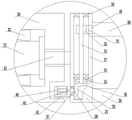
Fig. 2 is an enlarged schematic view of a portion a in fig. 1.
FIG. 3 is a schematic sectional view showing an enlarged structure of B-B in FIG. 1.
In the figure: 1. the device comprises a machine body, 2, a transverse sliding rail, 3, a transverse sliding seat, 4, a transverse ball screw pair, 5, a longitudinal sliding rail, 6, a longitudinal sliding seat, 7, a longitudinal ball screw pair, 8, a vertical air cylinder, 9, a vertical piston rod, 10, a transverse grinding head motor, 11, a motor shaft, 12, a grinding head, 13, a first bearing seat, 14, a magnetic workbench, 15, a first servo speed reduction motor, 16, a magnetic switch, 17, a transverse drain tank, 18, a hydraulic cylinder group, 19, a hydraulic rod, 20, a supporting frame, 21, a second bearing seat, 22, a transverse air cylinder, 23, a transverse piston rod, 24, a turnover frame, 25, a second servo speed reduction motor, 251, a second motor shaft, 26, a lower clamping long plate, 27, a vertical sliding tank, 28, a vertical sliding block, 29, an upper clamping long plate, 30, a third bearing seat, 31, a vertical screw rod, 32, a vertical screw sleeve, 33, a connecting block, 34, a vertical screw rod, a vertical sliding block, a, The chain wheel 35, the chain 36, the driven bevel gear 37, the fourth bearing seat 38, the gear shaft 39, the driving bevel gear 40, the third servo speed reducing motor 41, the third motor shaft 42, the motor frame 43, the guide sleeve 44, the guide rod 45 and the workpiece.
Detailed Description
The following detailed description of the present invention will be made in conjunction with the accompanying drawings and specific embodiments.
As shown in fig. 1, 2 and 3, the high-precision horizontal spindle circular table surface grinder includes: the grinding machine comprises a machine body 1, wherein a transverse sliding rail 2 is arranged at the upper end of the machine body 1, a transverse sliding seat 3 is arranged on the transverse sliding rail 2 in a sliding manner, a transverse ball screw pair 4 is arranged at the upper end of the machine body 1, the transverse ball screw pair 4 is connected with a transverse driving device, the transverse sliding seat 3 is connected with the transverse ball screw pair 4 through a transverse flexible connecting device, a longitudinal sliding rail 5 is arranged at the lower end of the transverse sliding seat 3, a longitudinal sliding seat 6 is arranged on the longitudinal sliding rail 5 in a sliding manner, a longitudinal ball screw pair 7 is arranged at the lower end of the transverse sliding seat 3, the longitudinal ball screw pair 7 is connected with a longitudinal driving device, the longitudinal sliding seat 6 is connected with the longitudinal ball screw pair 7 through a longitudinal flexible connecting device, a vertical air cylinder 8 is arranged on the longitudinal sliding seat 6, and a transverse grinding head motor 10 is arranged at the lower end of a vertical piston rod 9 of the vertical air cylinder 8, be provided with bistrique 12 on the motor shaft 11 of horizontal bistrique motor 10 the lower extreme middle part of fuselage 1 rotates through first bearing frame 13 and is provided with magnetic force workstation 14, the lower extreme of magnetic force workstation 14 is connected with the first motor shaft of first servo gear motor 15, first servo gear motor 15 is fixed to be set up on fuselage 1 the lower extreme of magnetic force workstation 14 is provided with the magnetic switch 16 who is connected with it the upper end of magnetic force workstation 14 evenly is provided with a plurality of horizontal hydrophobic grooves 17 the bilateral symmetry of horizontal hydrophobic groove 17 is provided with presss from both sides material turning device, press from both sides material turning device's structure and include: a hydraulic cylinder group 18 arranged at the lower end of the machine body 1, a support frame 20 arranged at the upper end of a hydraulic rod 19 of the hydraulic cylinder group 18, a transverse cylinder 22 rotatably arranged in the support frame 20 through a second bearing seat 21, a transverse piston rod 23 of the transverse cylinder 22 extending out of the support frame 20 and connected with a roll-over stand 24, the tail part of the transverse cylinder 22 far away from the magnetic workbench 14 is connected with a second motor shaft 251 of a second servo speed-reducing motor 25, the second servo speed-reducing motor 25 is fixedly arranged on the support frame 20, a plurality of lower material clamping long plates 26 matched with the drainage groove 17 are uniformly arranged at the lower end of the roll-over stand 24, a plurality of vertical sliding grooves 27 corresponding to the lower material clamping long plates 26 one by one are uniformly arranged at one side of the roll-over stand 24 close to the magnetic workbench 14, and vertical sliding blocks 28 matched with the vertical sliding blocks are respectively arranged in the vertical sliding grooves 27, an upper clamping long plate 29 matched with the drain groove 17 is respectively arranged at one side of the vertical sliding block 28 close to the magnetic workbench 14, a plurality of vertical screw rods 31 corresponding to the vertical sliding grooves 27 in a one-to-one manner are rotatably arranged in the roll-over stand 24 through a third bearing seat 30, vertical screw sleeves 32 matched with the vertical screw rods 31 are respectively arranged on the vertical screw rods 31, the vertical screw sleeves 32 are connected with the other side of the vertical sliding block 28 far away from the magnetic workbench 14 through connecting blocks 33, chain wheels 34 are respectively arranged at the lower ends of the vertical screw rods 31, the chain wheels 34 are connected through chains 35, a driven bevel gear 36 is arranged at the lower end of one vertical screw rod 31, a gear shaft 38 is rotatably arranged at the lower end of the other side of the roll-over stand 24 far away from the magnetic workbench 14 through a fourth bearing seat 37, and a driving bevel gear 39 meshed with the driven bevel gear 36 is arranged at one end of the gear shaft 38 extending into the roll-over stand 24, the other end of the gear shaft 38 extending out of the roll-over stand 24 is connected with a third motor shaft 41 of a third servo gear motor 40, and the third servo gear motor 40 is fixedly arranged on the roll-over stand 24 through a motor frame 42.
As shown in fig. 1, in this example, for smoother polishing, guide sleeves 43 are symmetrically disposed on the longitudinal slide 6 at both sides of the vertical cylinder 8, and guide rods 44 slidably engaged with the guide sleeves 43 are symmetrically disposed at both sides of the upper end of the transverse grinding head motor 10.
When the grinding head device works, a workpiece 45 is placed in the center of a magnetic workbench 14, strong magnetism on the magnetic workbench 14 is turned on through a magnetic switch 16, the magnetic workbench 14 performs strong adsorption positioning on the workpiece 45, a first servo speed reduction motor 15 is started, a first motor shaft of the first servo speed reduction motor 15 drives the magnetic workbench 14 to rotate on a first bearing seat 13, a transverse driving device is started to drive a transverse sliding seat 3 to transversely move on a transverse sliding rail 2 through a transverse ball screw pair 4, a longitudinal driving device is started to drive a longitudinal sliding seat 6 to longitudinally move on a longitudinal sliding rail 5 through a longitudinal ball screw pair 7, a vertical cylinder 8 is started, a vertical piston rod 9 of the vertical cylinder 8 drives a transverse grinding head motor 10 to vertically move, the transverse grinding head motor 10 also vertically slides in a guide sleeve 43 through a guide rod 44, and three-dimensional adjustment of the position of a grinding head 12 is realized, the transverse grinding head motor 10 is started, a motor shaft 11 of the transverse grinding head motor 10 drives the grinding head 12 to rotate, the grinding head 12 polishes the upper surface of the workpiece 45 through transverse, longitudinal and vertical position movement, after polishing is completed, all parts reset, and the first servo speed reducing motor 15 restores to the original point to ensure that the transverse drain groove 17 on the magnetic workbench 14 is in a transverse horizontal position.
When the upper surface of a workpiece 45 is turned over after being polished, the strong magnetism on the magnetic workbench 14 is closed through the magnetic switch 16, two transverse air cylinders 22 are started, transverse piston rods 23 of the two transverse air cylinders 22 respectively drive two turning frames 24 to move towards the magnetic workbench 14, the turning frames 24 drive a plurality of lower material clamping long plates 26 and upper material clamping long plates 29 to move towards the magnetic workbench 14 together, the lower material clamping long plates 26 are respectively inserted into the corresponding transverse drain grooves 17 at the lower end of the workpiece 45 until moving to the bottom of the workpiece 45, the upper material clamping long plates 29 move to the upper part of the workpiece 45, a third servo reducing motor 40 is started, a third motor shaft 41 of the third servo reducing motor 40 drives a gear shaft 38 to rotate in a fourth bearing seat 37, the gear shaft 38 drives a driving bevel gear 39 to rotate, and the driving bevel gear 39 drives a driven bevel gear 36 meshed with the driving bevel gear to rotate, the driven bevel gear 36 drives the vertical screw 31 connected with the driven bevel gear to rotate in the third bearing seat 30, the rotating vertical screw 31 drives the chain wheel 34 at the lower end of the rotating vertical screw to rotate, the rotating chain wheel 34 drives all the chain wheels 34 in the same roll-over stand 24 to rotate synchronously through the chain 35, the chain wheels 34 respectively drive all the corresponding vertical screws 31 to rotate synchronously, the vertical screw 31 drives the vertical screw sleeve 32 matched with the vertical screw sleeve to move downwards, the vertical screw sleeve 32 drives the vertical slide block 28 to slide downwards in the vertical slide groove 27 through the connecting block 33, the vertical slide block 28 respectively drives the upper material clamping long plate 29 to move downwards to abut against the workpiece 45, the hydraulic cylinder group 18 is started, the hydraulic cylinder 19 of the hydraulic cylinder group 18 drives the supporting frame 20 to move upwards, the supporting frame 20 drives the roll-over stand 24 to move upwards, and the roll-over stand 24 drives the workpiece 45 to move upwards through the lower material clamping long plate 26 and the upper material clamping long plate 29, when the lower long clamping plate 26 moves out of the transverse drain tank 17 upwards, the third servo deceleration motor 40 is continuously started to enable the upper long clamping plate 29 to continuously move downwards to apply pressure on the workpiece 45, so as to realize clamping, the second servo deceleration motor 25 is started, the second motor shaft 251 of the second servo deceleration motor 25 drives the transverse cylinder 22 to turn 180 degrees on the support frame 20 through the second bearing seat 21, the transverse cylinder 22 drives the roll-over stand 24 to turn 180 degrees, the roll-over stand 24 drives the workpiece 45 to turn 180 degrees through the lower long clamping plate 26 and the upper long clamping plate 29, at this time, the upper long clamping plate 29 is located below, the lower long clamping plate 26 is located above, the hydraulic cylinder group 18 is started again, the hydraulic cylinder 19 of the hydraulic cylinder group 18 drives the support frame 20 to move downwards, the support frame 20 drives the roll-over stand 24 to move downwards, the roll-over stand 24 drives the workpiece 45 to move downwards through the upper long clamping plate 26 located above and the upper long clamping plate 29 located below, when the upper clamping long plate 29 positioned below moves into the transverse hydrophobic groove 17 and does not completely enter, the third servo speed reducing motor 40 is continuously started to enable the upper material clamping long plate 29 located below to move downwards to release clamping of the workpiece 45, the workpiece 45 is separated from the lower material clamping long plate 26 located below, the upper material clamping long plate 29 located below is continuously moved downwards to completely enter the transverse drain tank 17, the workpiece 45 is flatly placed on the magnetic workbench 14, the upper material clamping long plate 29 located below is separated from the workpiece 45, the transverse air cylinder 22 is reset to drive the lower material clamping long plate 26 located above and the upper material clamping long plate 29 located below to be away from the magnetic workbench 14 until the workpiece is completely separated, the hydraulic cylinder group 18 is started again, and the hydraulic cylinders 19 of the hydraulic cylinder group 18 drive the support frame 20 to move downwards to the two sides of the magnetic workbench 14 to prevent interference with the transverse grinding head motor 10 in the next working process.
The high-precision horizontal-shaft circular-table surface grinding machine is novel in structure, capable of automatically turning the workpiece again, stable in turning, accurate in positioning, high in automation degree, high in working efficiency and high in machining precision, and reduces labor intensity of workers.
Claims (2)
1. High accuracy horizontal axis round platform flat grinder, its characterized in that: the method comprises the following steps: fuselage (1) the upper end of fuselage (1) is provided with horizontal slide rail (2) slide on horizontal slide rail (2) and be provided with horizontal slide (3) the upper end of fuselage (1) is provided with horizontal ball screw pair (4), horizontal ball screw pair (4) is connected with horizontal drive arrangement, horizontal slide (3) are connected with horizontal ball screw pair (4) through horizontal flexible coupling device the lower extreme of horizontal slide (3) is provided with vertical slide rail (5) slide on vertical slide rail (5) and be provided with vertical slide (6) the lower extreme of horizontal slide (3) is provided with vertical ball screw pair (7), vertical ball screw pair (7) is connected with vertical drive arrangement, vertical slide (6) are connected with vertical ball screw pair (7) through vertical flexible coupling device, a vertical cylinder (8) is arranged on the longitudinal sliding seat (6), a transverse grinding head motor (10) is arranged at the lower end of a vertical piston rod (9) of the vertical cylinder (8), a grinding head (12) is arranged on a motor shaft (11) of the transverse grinding head motor (10), a magnetic workbench (14) is rotatably arranged in the middle of the lower end of the machine body (1) through a first bearing seat (13), the lower end of the magnetic workbench (14) is connected with a first motor shaft of a first servo speed reduction motor (15), the first servo speed reduction motor (15) is fixedly arranged on the machine body (1), a magnetic switch (16) connected with the magnetic workbench (14) is arranged at the lower end of the magnetic workbench (14), a plurality of transverse drain grooves (17) are uniformly arranged at the upper end of the magnetic workbench (14), and clamping turnover devices are symmetrically arranged on two sides of the transverse drain grooves (17), the structure of the clamping and turning device comprises: the hydraulic cylinder group (18) is arranged at the lower end of the machine body (1), a supporting frame (20) is arranged at the upper end of a hydraulic rod (19) of the hydraulic cylinder group (18), a transverse cylinder (22) is rotatably arranged in the supporting frame (20) through a second bearing seat (21), a transverse piston rod (23) of the transverse cylinder (22) extends out of the supporting frame (20) to be connected with a roll-over stand (24), the tail part of the transverse cylinder (22) far away from the magnetic workbench (14) is connected with a second motor shaft (251) of a second servo speed reduction motor (25), the second servo speed reduction motor (25) is fixedly arranged on the supporting frame (20), a plurality of lower material clamping long plates (26) matched with the drainage groove (17) are uniformly arranged at the lower end of the roll-over stand (24), a plurality of vertical sliding grooves (27) corresponding to the lower material clamping long plates (26) one by one are uniformly arranged on one side of the roll-over stand (24) close to the magnetic workbench (14), vertical sliding blocks (28) matched with the vertical sliding blocks are arranged in the vertical sliding grooves (27) in a sliding mode respectively, upper material clamping long plates (29) matched with the water drainage grooves (17) are arranged on one sides, close to the magnetic workbench (14), of the vertical sliding blocks (28) respectively, a plurality of vertical screw rods (31) corresponding to the vertical sliding grooves (27) one by one are arranged in the turnover frame (24) in a rotating mode through third bearing seats (30), vertical screw sleeves (32) matched with the vertical screw rods (31) are arranged on the vertical screw rods (31) respectively, the vertical screw sleeves (32) are connected with the other side, far away from the magnetic workbench (14), of the vertical sliding blocks (28) through connecting blocks (33), chain wheels (34) are arranged at the lower ends of the vertical screw rods (31) respectively, the chain wheels (34) are connected through chains (35), and driven bevel gears (36) are arranged at the lower end of one vertical screw rod (31), a gear shaft (38) is rotatably arranged at the lower end of the other side, far away from the magnetic workbench (14), of the turning frame (24) through a fourth bearing seat (37), a driving bevel gear (39) meshed with the driven bevel gear (36) is arranged at one end, extending into the turning frame (24), of the gear shaft (38), the other end, extending out of the turning frame (24), of the gear shaft (38) is connected with a third motor shaft (41) of a third servo speed reducing motor (40), and the third servo speed reducing motor (40) is fixedly arranged on the turning frame (24) through a motor frame (42).
2. The high-precision horizontal-axis circular truncated cone surface grinding machine according to claim 1, characterized in that: guide sleeves (43) are symmetrically arranged on the longitudinal sliding seats (6) on two sides of the vertical cylinder (8), and guide rods (44) in sliding fit with the guide sleeves (43) are symmetrically arranged on two sides of the upper end of the transverse grinding head motor (10).
Priority Applications (1)
| Application Number | Priority Date | Filing Date | Title |
|---|---|---|---|
| CN202022153248.5U CN213970313U (en) | 2020-09-27 | 2020-09-27 | High-precision horizontal-shaft circular-table surface grinding machine |
Applications Claiming Priority (1)
| Application Number | Priority Date | Filing Date | Title |
|---|---|---|---|
| CN202022153248.5U CN213970313U (en) | 2020-09-27 | 2020-09-27 | High-precision horizontal-shaft circular-table surface grinding machine |
Publications (1)
| Publication Number | Publication Date |
|---|---|
| CN213970313U true CN213970313U (en) | 2021-08-17 |
Family
ID=77256397
Family Applications (1)
| Application Number | Title | Priority Date | Filing Date |
|---|---|---|---|
| CN202022153248.5U Active CN213970313U (en) | 2020-09-27 | 2020-09-27 | High-precision horizontal-shaft circular-table surface grinding machine |
Country Status (1)
| Country | Link |
|---|---|
| CN (1) | CN213970313U (en) |
Cited By (1)
| Publication number | Priority date | Publication date | Assignee | Title |
|---|---|---|---|---|
| CN114932494A (en) * | 2022-06-21 | 2022-08-23 | 安徽中磁高科有限公司 | Surface polishing equipment and polishing method for machining of motor parts |
-
2020
- 2020-09-27 CN CN202022153248.5U patent/CN213970313U/en active Active
Cited By (1)
| Publication number | Priority date | Publication date | Assignee | Title |
|---|---|---|---|---|
| CN114932494A (en) * | 2022-06-21 | 2022-08-23 | 安徽中磁高科有限公司 | Surface polishing equipment and polishing method for machining of motor parts |
Similar Documents
| Publication | Publication Date | Title |
|---|---|---|
| CN111716202B (en) | Automatic grinding device of work piece arc surface | |
| CN213970313U (en) | High-precision horizontal-shaft circular-table surface grinding machine | |
| CN112091745A (en) | High-precision horizontal-shaft circular-table surface grinding machine | |
| CN212824390U (en) | Full-automatic right-angle welding seam polisher | |
| CN219337137U (en) | Casting finish machining machine tool | |
| CN209954337U (en) | Special automobile spare and accessory part machining center | |
| CN204819057U (en) | Automatic burnishing and polishing machine of small -size metal specimen | |
| CN113695127B (en) | Electromechanical integrated numerical control spraying machine tool | |
| CN215659476U (en) | Grinding device is used in steel casting production | |
| CN110640224B (en) | Tire mould carving machine | |
| CN108568723A (en) | Mirrors fine-grinding and polishing device | |
| CN210010675U (en) | Round bar polishing machine | |
| CN109623418B (en) | Special automobile spare and accessory part machining center | |
| CN214445232U (en) | Stone processing equipment | |
| CN219853518U (en) | Long external diameter processing is with exempting from abluent processingequipment | |
| CN219504410U (en) | Grinding machine for automobile parts | |
| CN217513548U (en) | Grinding device for optical lens | |
| CN219504543U (en) | Precision machining platform | |
| CN112548753B (en) | Round piece corner chamfer device of polishing | |
| CN216327045U (en) | Automatic feeding device for machining of cylindrical grinding machine | |
| CN109290807A (en) | Double-station precise machining device | |
| CN215148007U (en) | Quick workpiece changing structure of high-precision polishing machine | |
| CN213106050U (en) | Surface polishing tool for steel telescopic guide rail protective cover of machine tool | |
| CN218341664U (en) | Burnishing device of accurate metalworking | |
| CN219521577U (en) | Optical lens polishing device |
Legal Events
| Date | Code | Title | Description |
|---|---|---|---|
| GR01 | Patent grant | ||
| GR01 | Patent grant |