CN213945797U - Automatic sand-adding chamfering lathe - Google Patents
Automatic sand-adding chamfering lathe Download PDFInfo
- Publication number
- CN213945797U CN213945797U CN202023211477.4U CN202023211477U CN213945797U CN 213945797 U CN213945797 U CN 213945797U CN 202023211477 U CN202023211477 U CN 202023211477U CN 213945797 U CN213945797 U CN 213945797U
- Authority
- CN
- China
- Prior art keywords
- fixedly connected
- operation panel
- sweeps
- slide rail
- slider
- Prior art date
- Legal status (The legal status is an assumption and is not a legal conclusion. Google has not performed a legal analysis and makes no representation as to the accuracy of the status listed.)
- Active
Links
Images


Landscapes
- Auxiliary Devices For Machine Tools (AREA)
Abstract
The utility model relates to the technical field of lathes, a automatic sand adding chamfering lathe is disclosed, the on-line screen storage device comprises a base, the top fixedly connected with bracing piece of base, the top fixedly connected with operation panel of bracing piece, the outer fixed surface of operation panel is connected with the slide rail, the inner wall sliding connection of slide rail has the slider, the top fixedly connected with blower housing of slider. The utility model has the advantages of it is following and effect: through setting up the slide rail, the slider, the blower housing, the air-supply line, box hair-dryer and baffle, when clearing up the sweeps on the operation panel, only need will blow the cover and follow the slide rail and stimulate right side, then start box hair-dryer, box hair-dryer arrives the blower housing at the wind-supply line with the wind that produces at the during operation, blow in the collecting tank with the sweeps on the operation panel, accomplish the clearance to the sweeps promptly, this design easy operation, it is convenient to use, reached the device and be convenient for carry out the effect of clearing up to the sweeps.
Description
Technical Field
The utility model relates to a lathe technical field, in particular to automatic add husky chamfer lathe.
Background
The lathe is a machine tool for turning a rotating workpiece mainly by using a lathe tool, and can also perform corresponding processing by using a drill bit, a reamer, a screw tap, a die, a knurling tool and the like on the lathe, and the types of the lathe can be divided into a general lathe, a turret and rotary lathe, an automatic lathe, a multi-tool semi-automatic lathe and the like.
Automatic among the prior art add husky chamfer lathe, when carrying out the chamfer to the work piece and add man-hour, often can produce a large amount of residue sweeps in the top on the operation panel, all adopt the manual work to use brush or other cleaning means to clear up the sweeps on the operation panel among the prior art usually, not only clean inefficiency, need consume a large amount of labours moreover.
SUMMERY OF THE UTILITY MODEL
The utility model aims at providing an automatic add husky chamfer lathe has the effect of the sweeps on the clean operation panel of being convenient for.
The above technical purpose of the present invention can be achieved by the following technical solutions: the utility model provides an automatic add husky chamfer lathe, includes the base, the top fixedly connected with bracing piece of base, the top fixedly connected with operation panel of bracing piece, the outer fixed surface of operation panel is connected with the slide rail, the inner wall sliding connection of slide rail has the slider, the top fixedly connected with blower housing of slider, the outer fixed surface of blower housing is connected with the air-supply line, the box hair-dryer of one end fixedly connected with of air-supply line, the top fixedly connected with baffle of operation panel.
Through adopting the above technical scheme, through setting up the slide rail, the slider, the blower housing, the air-supply line, box hair-dryer and baffle, when clearing up the sweeps on the operation panel, only need will blow the cover and follow the slide rail and stimulate to the right side, then start box hair-dryer, box hair-dryer arrives the blower housing at the wind-supply line with the wind that produces at the during operation, blow in the collecting tank with the sweeps on the operation panel, accomplish the clearance to the sweeps promptly, the baffle can play the effect that stops the sweeps at the in-process of blowing, prevent that the sweeps from dropping to ground, this design easy operation, high durability and convenient use, the device has been reached and is convenient for carry out the effect of clearing up the sweeps.
The utility model discloses a further set up to: the top of the operating platform is fixedly connected with a driving case, a driving motor is arranged inside the driving case, and the output end of the driving motor is fixedly connected with a rotary clamping part.
Through adopting above-mentioned technical scheme, rotatory clamping part plays the effect of fixed work piece of treating processing.
The utility model discloses a further set up to: the top of operation panel fixedly connected with sliding seat, the top of sliding seat is provided with the cutter.
By adopting the technical scheme, the cutter can move left and right on the sliding seat.
The utility model discloses a further set up to: the upper surface of operation panel has seted up the groove that gathers materials, the bottom fixedly connected with row of material storehouse of the groove that gathers materials.
Through adopting above-mentioned technical scheme, arrange the silo and be located the top of collecting box, the sweeps that gets into in arranging the silo and receive the action of gravity to drop to the collecting box in.
The utility model discloses a further set up to: the top fixedly connected with collecting box of base, one side fixedly connected with pneumatic cylinder of collecting box, the output fixedly connected with push pedal of pneumatic cylinder.
Through adopting above-mentioned technical scheme, through setting up collecting box, pneumatic cylinder and push pedal, the sweeps of collecting gets into the collecting box through arranging the storehouse inside, then can drive the push pedal and remove to the left through starting the pneumatic cylinder, compresses the inside sweeps of collecting box, is convenient for follow-up retrieve and recycle the sweeps.
The utility model discloses a further set up to: the bottom fixedly connected with pulley of base, the quantity of pulley is four.
Through adopting above-mentioned technical scheme, through setting up the pulley, make things convenient for the staff to remove the device.
The utility model has the advantages that: by arranging the sliding rail, the sliding block, the blowing hood, the air inlet pipe, the box-type blower and the baffle, when the scraps on the operating platform are cleaned, the blowing hood only needs to be pulled rightwards along the sliding rail, then the box-type blower is started, the box-type blower can generate air from the air inlet pipe to the blowing hood when in work, the scraps on the operating platform are blown into the collecting tank, the cleaning of the scraps is finished, the baffle can play a role in stopping the scraps in the blowing process, and the scraps are prevented from falling to the ground; through setting up collecting box, pneumatic cylinder and push pedal, the sweeps of collecting get into inside the collecting box through arranging the silo, then can drive the push pedal and remove to the left through starting the pneumatic cylinder, compress the inside sweeps of collecting box, be convenient for follow-up retrieve and recycle the sweeps.
Drawings
In order to more clearly illustrate the technical solutions in the embodiments of the present invention, the drawings needed to be used in the description of the embodiments will be briefly described below, and it is obvious that the drawings in the following description are only some embodiments of the present invention, and it is obvious for those skilled in the art to obtain other drawings without creative efforts.
Fig. 1 is a schematic structural view of the present invention;
FIG. 2 is a schematic structural view of the middle collecting trough of the present invention;
FIG. 3 is a schematic structural view of the slider of the present invention;
fig. 4 is a schematic structural view of the middle push plate of the present invention.
In the figure, 1, a base; 2. a support bar; 3. an operation table; 4. a slide rail; 5. a slider; 6. a blower housing; 7. an air inlet pipe; 8. a box-type blower; 9. a baffle plate; 10. a drive chassis; 11. a rotating clamping part; 12. a sliding seat; 13. a cutter; 14. a trough; 15. a material discharging bin; 16. a collection box; 17. a hydraulic cylinder; 18. pushing the plate; 19. a pulley.
Detailed Description
The technical solution of the present invention will be clearly and completely described below with reference to the specific embodiments. It is obvious that the described embodiments are only some of the embodiments of the present invention, and not all of them. Based on the embodiments of the present invention, all other embodiments obtained by a person of ordinary skill in the art without creative efforts belong to the protection scope of the present invention.
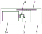
Referring to fig. 1-4, an automatic sand adding chamfering lathe comprises a base 1, a support rod 2 is fixedly connected to the top of the base 1, an operation table 3 is fixedly connected to the top of the support rod 2, a slide rail 4 is fixedly connected to the outer surface of the operation table 3, a slide block 5 is slidably connected to the inner wall of the slide rail 4, a blowing hood 6 is fixedly connected to the top of the slide block 5, an air inlet pipe 7 is fixedly connected to the outer surface of the blowing hood 6, a box-type blower 8 is fixedly connected to one end of the air inlet pipe 7, a baffle 9 is fixedly connected to the top of the operation table 3, when waste chips on the operation table 3 are cleaned through the slide rail 4, the slide block 5, the blowing hood 6, the air inlet pipe 7, the box-type blower 8 and the baffle 9, the blowing hood 6 only needs to be pulled rightwards along the slide rail 4, then the box-type blower 8 is started, and the box-type blower 8 reaches the blowing hood 6 from the air inlet pipe 7 when in operation, the waste scraps on the operation table 3 are blown into the collecting groove 14, the cleaning of the waste scraps is completed, the baffle plate 9 can play a role of blocking the waste scraps in the blowing process, the waste scraps are prevented from falling to the ground, the design operation is simple, the use is convenient, the effect of cleaning the waste scraps by the device is achieved, the top of the operation table 3 is fixedly connected with a driving machine case 10, a driving motor is arranged inside the driving machine case 10, the output end of the driving motor is fixedly connected with a rotary clamping part 11, the rotary clamping part 11 plays a role of fixing a workpiece to be processed, the top of the operation table 3 is fixedly connected with a sliding seat 12, a cutter 13 is arranged at the top of the sliding seat 12, the cutter 13 can move left and right on the sliding seat 12, the collecting groove 14 is arranged on the upper surface of the operation table 3, the bottom of the collecting groove 14 is fixedly connected with a discharging bin 15, the discharging bin 15 is positioned above a collecting box 16, get into the sweeps in arranging the material storehouse 15 and drop to the collecting box 16 in by action of gravity, base 1's top fixedly connected with collecting box 16, one side fixedly connected with pneumatic cylinder 17 of collecting box 16, pneumatic cylinder 17's output fixedly connected with push pedal 18, through setting up collecting box 16, pneumatic cylinder 17 and push pedal 18, the sweeps of collection gets into inside collecting box 16 through arranging material storehouse 15, then can drive push pedal 18 and remove left through starting up pneumatic cylinder 17, compress the inside sweeps of collecting box 16, be convenient for follow-up retrieve and recycle the sweeps, base 1's bottom fixedly connected with pulley 19, pulley 19's quantity is four, through setting up pulley 19, make things convenient for the staff to remove the device.
In the utility model, by arranging the slide rail 4, the slide block 5, the blowing cover 6, the air inlet pipe 7, the box-type blower 8 and the baffle 9, when the scraps on the operation table 3 are cleaned, only the blowing cover 6 is pulled to the right along the slide rail 4, then the box-type blower 8 is started, the box-type blower 8 reaches the blowing cover 6 from the air inlet pipe 7 when working, the scraps on the operation table 3 are blown into the collecting tank 14, the cleaning of the scraps is completed, the baffle 9 can play a role of blocking the scraps in the blowing process, the scraps are prevented from falling to the ground, the design operation is simple, the use is convenient, the effect of the device for cleaning the scraps is achieved, by arranging the collecting tank 16, the hydraulic cylinder 17 and the push plate 18, the collected scraps can enter the collecting tank 16 through the discharging bin 15, then the push plate 18 can be driven to move to the left by starting the hydraulic cylinder 17, the waste chips inside the collection box 16 are compressed, so that the waste chips can be recovered and reused subsequently.
Claims (6)
1. The utility model provides an automatic add husky chamfer lathe, includes base (1), its characterized in that: the utility model discloses a fan, including base (1), top fixedly connected with bracing piece (2), the top fixedly connected with operation panel (3) of bracing piece (2), the external fixed surface of operation panel (3) is connected with slide rail (4), the inner wall sliding connection of slide rail (4) has slider (5), the top fixedly connected with blower housing (6) of slider (5), the external fixed surface of blower housing (6) is connected with air-supply line (7), the box hair-dryer (8) of one end fixedly connected with of air-supply line (7), the top fixedly connected with baffle (9) of operation panel (3).
2. The automatic sanding chamfering lathe according to claim 1, characterized in that: the top of the operating platform (3) is fixedly connected with a driving case (10), a driving motor is arranged inside the driving case (10), and the output end of the driving motor is fixedly connected with a rotary clamping part (11).
3. The automatic sanding chamfering lathe according to claim 1, characterized in that: the top of the operating platform (3) is fixedly connected with a sliding seat (12), and the top of the sliding seat (12) is provided with a cutter (13).
4. The automatic sanding chamfering lathe according to claim 1, characterized in that: the upper surface of operation panel (3) has seted up material collecting tank (14), the bottom fixedly connected with row material storehouse (15) of material collecting tank (14).
5. The automatic sanding chamfering lathe according to claim 1, characterized in that: the top fixedly connected with collecting box (16) of base (1), one side fixedly connected with pneumatic cylinder (17) of collecting box (16), the output fixedly connected with push pedal (18) of pneumatic cylinder (17).
6. The automatic sanding chamfering lathe according to claim 1, characterized in that: the bottom fixedly connected with pulley (19) of base (1), the quantity of pulley (19) is four.
Priority Applications (1)
| Application Number | Priority Date | Filing Date | Title |
|---|---|---|---|
| CN202023211477.4U CN213945797U (en) | 2020-12-28 | 2020-12-28 | Automatic sand-adding chamfering lathe |
Applications Claiming Priority (1)
| Application Number | Priority Date | Filing Date | Title |
|---|---|---|---|
| CN202023211477.4U CN213945797U (en) | 2020-12-28 | 2020-12-28 | Automatic sand-adding chamfering lathe |
Publications (1)
| Publication Number | Publication Date |
|---|---|
| CN213945797U true CN213945797U (en) | 2021-08-13 |
Family
ID=77194610
Family Applications (1)
| Application Number | Title | Priority Date | Filing Date |
|---|---|---|---|
| CN202023211477.4U Active CN213945797U (en) | 2020-12-28 | 2020-12-28 | Automatic sand-adding chamfering lathe |
Country Status (1)
| Country | Link |
|---|---|
| CN (1) | CN213945797U (en) |
Cited By (1)
| Publication number | Priority date | Publication date | Assignee | Title |
|---|---|---|---|---|
| CN114226677A (en) * | 2021-11-19 | 2022-03-25 | 徐州达一锻压设备有限公司 | Material collecting device of hydraulic machine |
-
2020
- 2020-12-28 CN CN202023211477.4U patent/CN213945797U/en active Active
Cited By (1)
| Publication number | Priority date | Publication date | Assignee | Title |
|---|---|---|---|---|
| CN114226677A (en) * | 2021-11-19 | 2022-03-25 | 徐州达一锻压设备有限公司 | Material collecting device of hydraulic machine |
Similar Documents
| Publication | Publication Date | Title |
|---|---|---|
| CN107378632A (en) | A kind of machining center of quick recovery cooling oil | |
| CN213945797U (en) | Automatic sand-adding chamfering lathe | |
| CN211589210U (en) | Numerical control drilling and milling machine for machining | |
| CN211489707U (en) | Radial drill convenient to retrieve coolant liquid | |
| CN216461763U (en) | Novel numerical control lathe | |
| CN112705990A (en) | Vertical double-head double-cutter milling machine machining center | |
| CN106693489A (en) | Cutting fluid filtering and recycling device | |
| CN212763796U (en) | Machine table cleaning device for drawing strip production | |
| CN214418300U (en) | Automatic milling cutter machine tool for clean production | |
| CN210060559U (en) | Milling machine sweeps recovery unit | |
| CN210967051U (en) | Drilling machine convenient to centre gripping and clearance piece | |
| CN210850669U (en) | Wood chip treatment facility for wood working | |
| CN219054687U (en) | Automatic feeding and discharging numerical control lathe | |
| CN211489706U (en) | Radial drill convenient to clearance waste material | |
| CN221231620U (en) | Digital display horizontal milling and boring machine | |
| CN220217670U (en) | Drilling machine for machining | |
| CN215746618U (en) | Horizontal milling and vertical milling two-in-one equipment | |
| CN219648784U (en) | Milling machine for processing edge die | |
| CN214684584U (en) | Gear planer with waste bits rolling drying cleaning function | |
| CN215999708U (en) | High-efficient numerical control lathe | |
| CN215145035U (en) | Semi-automatic bottom milling machine for door and window handle seat | |
| CN221313471U (en) | Cnc engraving and milling machine convenient to clearance | |
| CN218964821U (en) | Numerical control machine tool for metal processing convenient for waste recovery and filtration | |
| CN220515435U (en) | Multi-station numerical control lathe | |
| CN214236497U (en) | Anti-scratch numerical control cutting equipment for processing iron boxes |
Legal Events
| Date | Code | Title | Description |
|---|---|---|---|
| GR01 | Patent grant | ||
| GR01 | Patent grant |