CN213918909U - Building cement mortar mixing equipment - Google Patents
Building cement mortar mixing equipment Download PDFInfo
- Publication number
- CN213918909U CN213918909U CN202021729106.2U CN202021729106U CN213918909U CN 213918909 U CN213918909 U CN 213918909U CN 202021729106 U CN202021729106 U CN 202021729106U CN 213918909 U CN213918909 U CN 213918909U
- Authority
- CN
- China
- Prior art keywords
- fixedly connected
- disc
- baffle
- hose
- cement mortar
- Prior art date
- Legal status (The legal status is an assumption and is not a legal conclusion. Google has not performed a legal analysis and makes no representation as to the accuracy of the status listed.)
- Expired - Fee Related
Links
Images


Abstract
The utility model discloses a building cement mortar mixing device, which comprises a base, a support rod is fixedly connected with one side of the top of the base, a mixing tank is fixedly connected with one side of the support rod, a mixing component is arranged in the mixing tank, a ring disc is rotatably connected with the top of the mixing tank through a bearing, the water storage tank is fixedly connected with one side of the mixing tank, when the ring disc rotates, a hose is stretched and synchronously rotated, a water outlet hole at the rear side starts to discharge water when a baffle rotates, which is beneficial to cleaning the inner wall, and simultaneously can enable the water and the materials to be more fully mixed, the auger is fixedly connected with the bottom end of a rotating rod, the auger positively rotates to facilitate the discharge of the materials from a discharge port, when the materials are blocked, a motor reversely rotates to enable the auger to reversely rotate to drive the blocked materials upwards, thereby dredging the blockage, a split plate is rotatably connected with the bottom of the mixing tank through a rotating shaft, the mixing is more uniform, the cleaning is more convenient, the operation is simple, the labor intensity of workers is reduced, and the occurrence of outlet blockage is avoided.
Description
Technical Field
The utility model relates to a construction equipment technical field specifically is a building cement mortar mixing apparatus.
Background
At present, a large amount of concrete is needed in construction operation, but the existing common concrete stirring device is difficult to uniformly mix raw materials, and a large amount of mortar sediment is generated due to nonuniform stirring;
but the cement mortar agitating unit among the prior art stirring inhomogeneous, the raw materials easily bonds on jar internal wall, stirs inefficiency, leads to construction cost to increase, and the agitating unit after the practicality is not convenient for wash, has increased workman's intensity of labour.
SUMMERY OF THE UTILITY MODEL
An object of the utility model is to provide a building cement mortar mixing equipment to solve the problem among the above-mentioned background art.
In order to achieve the above object, the utility model provides a following technical scheme: a building cement mortar mixing device comprises a base, a supporting rod is fixedly connected with one side of the top of the base, one side of the supporting rod is fixedly connected with a stirring barrel, a stirring component is arranged in the stirring barrel and comprises a disc, a ring disc, a rotating rod, a connecting rod, a baffle, a hose, a packing auger and an opening plate, the ring disc is rotationally connected with the top of the stirring barrel through a bearing, the disc is arranged in the ring disc, the circular disc is rotationally connected with the annular disc through a bearing, the rotating rod penetrates through the circular disc and is rotationally connected with the circular disc through the bearing, a plurality of connecting rods are arranged, the connecting rods are fixedly connected with one side of the rotating rod, the baffle plate is fixedly connected with one side of the connecting rods, baffle fixed connection is in the ring dish bottom, hose fixed connection is inside the ring dish, auger and dwang bottom fixed connection, it rotates through the pivot with the agitator bottom to open the board and is connected.
Preferably, the top of the disc is fixedly connected with a protection plate, and the protection plate is arc-shaped.
Preferably, disc top fixedly connected with feed chute, disc bottom fixedly connected with motor, motor output and dwang fixed connection.
Preferably, open board one side fixedly connected with push rod, the baffle sets up in pressing close to the agitator inner wall.
Preferably, the top of the stirring barrel is fixedly connected with a fixed plate, and the hose penetrates through the fixed plate and is fixedly connected with the fixed plate.
Preferably, a water storage tank is fixed at the top of one side of the stirring barrel, the water storage tank is fixedly connected with a hose, and a switch valve is fixedly connected to the outer side of the hose.
Preferably, one side of the baffle is provided with a plurality of water outlet holes, and a water tank connected with the annular disc is arranged inside the baffle.
Compared with the prior art, the beneficial effects of the utility model are that:
1. the material is filled into the stirring barrel through the feeding groove, the motor is started to rotate positively, the output end of the motor is fixedly connected with the rotating rod, the motor drives the rotating rod to rotate, the front side and the rear side of the rotating rod are fixedly connected with a plurality of connecting rods, so that the stirring is more sufficient, the connecting rods are fixedly connected with the baffle, the baffle is arranged close to the inner wall of the stirring barrel, and when the rotating rod rotates, the baffle is driven to rotate, so that the material fixed on the inner wall of the stirring barrel is removed;
2. the water storage tank is fixedly connected with one side of the stirring barrel, the hose is fixedly connected with the water storage tank, the switch valve is arranged outside the hose, the control of the amount of added water is facilitated, the switch valve is opened, the hose is used for carrying out hose treatment on water inside the water storage tank, the hose is fixedly connected with the inside of the ring disc, the top of the disc is fixedly connected with a protection plate which is beneficial to avoiding winding around a motor when the hose rotates, the water outlet hole is arranged at the rear side of the rotation of the baffle, the water tank connected with the inside of the ring disc and the baffle is arranged, the water outlet hole at the rear side starts to discharge water when the baffle rotates, the inner wall is beneficial to cleaning, meanwhile, water and materials can be stirred more fully, the auger is fixedly connected with the bottom end of the rotating rod,
3. the screw conveyer positively rotates to accelerate the discharge of the material from the discharge port, when the material is blocked, the motor reversely rotates to drive the blocked material upwards in the reverse rotation of the screw conveyer, so that the blockage is dredged, the opening plate is rotatably connected with the bottom of the stirring barrel through the rotating shaft, the stirring is more uniform, the cleaning is more convenient, the operation is simple, the labor intensity of workers is reduced, and the outlet blockage is avoided.
Drawings
Fig. 1 is a schematic view of the overall structure of the present invention;
fig. 2 is a schematic front view of the cross-sectional structure of the present invention;
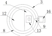
fig. 3 is a schematic top view of the present invention;
fig. 4 is an enlarged schematic structural view of fig. 3 according to the present invention;
in the figure: 1. a base; 2. a support bar; 3. a stirring barrel; 4. a disc; 5. a connecting rod; 6. a baffle plate; 7. A ring plate; 8. rotating the rod; 9. a hose; 10. a packing auger; 11. opening the plate; 12. a protection plate; 13. a feed chute; 14. a motor; 15. a fixing plate; 16. a water storage tank; 17. an on-off valve;
Detailed Description
The technical solutions in the embodiments of the present invention will be described clearly and completely with reference to the accompanying drawings in the embodiments of the present invention, and it is obvious that the described embodiments are only some embodiments of the present invention, not all embodiments. Based on the embodiments in the present invention, all other embodiments obtained by a person skilled in the art without creative work belong to the protection scope of the present invention.
Referring to fig. 1-4, the present invention provides an embodiment: a building cement mortar mixing device comprises a base 1, a supporting rod 2 is fixedly connected to one side of the top of the base 1, a stirring barrel 3 is fixedly connected to one side of the supporting rod 2, a fixing plate 15 is fixedly connected to the top of the stirring barrel 3, a hose 9 penetrates through the fixing plate 15 and is fixedly connected with the fixing plate 15, the hose 9 is favorably fixed, the hose 9 can be stretched, a water storage tank 16 is fixed to the top of one side of the stirring barrel 3, the water storage tank 16 is fixedly connected with the hose 9, a switch valve 17 is fixedly connected to the outer side of the hose 9, the water inflow amount is favorably controlled, the internal water inflow is kept, a stirring assembly is arranged in the stirring barrel 3 and comprises a disc 4, a ring disc 7, a rotating rod 8, a connecting rod 5, a baffle 6, the hose 9, an auger 10 and an opening plate 11, the ring disc 7 is rotatably connected with the top of the stirring barrel 3 through a bearing, the disc 4 is arranged in the ring disc 7, the disc 4 is rotatably connected with the ring disc 7 through a bearing, the top of the disc 4 is fixedly connected with a feeding chute 13, the bottom of the disc 4 is fixedly connected with a motor 14, the output end of the motor 14 is fixedly connected with a rotating rod 8, which is favorable for facilitating the material to enter, the top of the disc 4 is fixedly connected with a protection plate 12, the protection plate 12 is set to be arc-shaped, which is favorable for protecting the motor 14, and simultaneously, the hose 9 is prevented from winding the motor 14, the rotating rod 8 penetrates through the disc 4 and is rotatably connected with the disc 4 through a bearing, a plurality of connecting rods 5 are arranged, the connecting rods are fixedly connected with one side of the rotating rod 8, a baffle 6 is fixedly connected with one side of the connecting rod 5, the baffle 6 is fixedly connected with the bottom of the ring disc 7, one side of the baffle 6 is provided with a plurality of water outlet holes, a water tank connected with the ring disc 7 is arranged inside the baffle 6, which is favorable for the water to flow into the baffle 6, and simultaneously, the water and the material are stirred more uniformly, the hose 9 is fixedly connected inside the ring disc 7, and the bottom of the auger 10 is fixedly connected with the bottom end of the rotating rod 8, open 11 and be connected through the pivot rotation in 3 bottoms of agitator, open 11 one sides fixedly connected with push rods of board, baffle 6 sets up in pressing close to 3 inner walls of agitator, is favorable to clearing up the solidification sediment to 3 inner walls of agitator.
The implementation mode is specifically as follows; the material is filled into the stirring barrel 3 through the feeding groove 13, the motor 14 is opened to rotate positively, the output end of the motor 14 is fixedly connected with the rotating rod 8, the motor 14 drives the rotating rod 8 to rotate, the front side and the rear side of the rotating rod 8 are fixedly connected with a plurality of connecting rods 5, so that the stirring is more sufficient, the connecting rods 5 are fixedly connected with the baffle 6, the baffle 6 is arranged close to the inner wall of the stirring barrel 3, and the baffle 6 is driven to rotate when the rotating rod 8 rotates, so that the material fixed on the inner wall of the stirring barrel 3 is removed;
a water storage tank 16 is fixedly connected with one side of a stirring barrel 3, a hose 9 is fixedly connected with the water storage tank 16, a switch valve 17 is arranged on the outer side of the hose 9, which is favorable for controlling the amount of added water, the switch valve 17 is opened, the water in the water storage tank 16 is subjected to hose 9, the hose 9 is fixedly connected with the inner part of a ring disc 7, when the ring disc 7 rotates, the hose 9 is stretched and synchronously rotated, a protection plate 12 is fixedly connected with the top of a disc 4, which is favorable for the hose 9 to bypass a motor 14 to avoid winding when rotating, a water outlet hole is arranged on the rotating rear side of a baffle 6, the baffle 6 is fixedly connected with the ring disc 7, a connecting water tank is arranged in the ring disc 7 and the baffle 6, the water outlet hole on the rear side starts to discharge water when the baffle 6 rotates, which is favorable for cleaning the inner wall, and can ensure that the water and materials are stirred more fully, when the auger 10 is fixedly connected with the bottom end of a rotating rod 8, the auger 10 positively rotates to accelerate the discharge of the materials, when blockking up, 14 reversals of motor, make auger 10 reversal drive the material of jam upwards to make the jam mediation, open board 11 and agitator 3 bottoms and rotate through the pivot and be connected, the push rod with open 11 fixed connection of board, make through the push rod and open board 11 and rotate and open, the material that the stirring is good is poured, makes the stirring more even, and is clean more convenient, and easy operation has reduced workman's intensity of labour, avoids export obstructed production.
The working principle is as follows: the material is filled into the stirring barrel 3 through the feeding chute 13, the motor 14 is opened to rotate forwards, the output end of the motor 14 is fixedly connected with the rotating rod 8, the motor 14 drives the rotating rod 8 to rotate, the connecting rod 5 is fixedly connected with the baffle 6, the baffle 6 is driven to rotate when the rotating rod 8 rotates, the water storage tank 16 is fixedly connected to one side of the stirring barrel 3, the hose 9 is fixedly connected with the water storage tank 16, the switch valve 17 is opened, the water in the water storage tank 16 is subjected to hose 9, the hose 9 is fixedly connected with the inside of the ring disc 7, the baffle 6 is fixedly connected with the ring disc 7, the ring disc 7 is internally provided with a connected water chute, the water outlet hole at the rear side starts to discharge water when the baffle 6 rotates, the auger 10 is fixedly connected to the bottom end of the rotating rod 8, the auger 10 rotates forwards to facilitate the discharge of the material from the discharge hole, the motor 14 rotates backwards to enable the auger 10 to drive the blocked material upwards, and the push rod is fixedly connected with the opening plate 11, the push rod rotates the opening plate 11 open.
It is obvious to a person skilled in the art that the invention is not restricted to details of the above-described exemplary embodiments, but that it can be implemented in other specific forms without departing from the spirit or essential characteristics of the invention. The present embodiments are therefore to be considered in all respects as illustrative and not restrictive, the scope of the invention being indicated by the appended claims rather than by the foregoing description, and all changes which come within the meaning and range of equivalency of the claims are therefore intended to be embraced therein. Any reference sign in a claim should not be construed as limiting the claim concerned.
Claims (7)
1. The utility model provides a building cement mortar mixing apparatus, includes base (1), its characterized in that: a supporting rod (2) is fixedly connected to one side of the top of the base (1), a stirring barrel (3) is fixedly connected to one side of the supporting rod (2), and a stirring assembly is arranged in the stirring barrel (3);
the stirring assembly comprises a disc (4), a ring disc (7), a rotating rod (8), a connecting rod (5), a baffle (6), a hose (9), an auger (10) and an opening plate (11), wherein the ring disc (7) is rotatably connected with the top of the stirring barrel (3) through a bearing, the disc (4) is arranged inside the ring disc (7), the disc (4) is rotatably connected with the ring disc (7) through the bearing, the rotating rod (8) penetrates through the disc (4) and is rotatably connected with the disc (4) through the bearing, the connecting rod (5) is provided with a plurality of connecting rods which are fixedly connected to one side of the rotating rod (8), the baffle (6) is fixedly connected with one side of the connecting rod (5), the baffle (6) is fixedly connected to the bottom of the ring disc (7), the hose (9) is fixedly connected inside the ring disc (7), the auger (10) is fixedly connected with the bottom end of the rotating rod (8), the opening plate (11) is rotatably connected with the bottom of the stirring barrel (3) through a rotating shaft.
2. The building cement mortar mixing apparatus according to claim 1, wherein: the disc (4) is characterized in that a protection plate (12) is fixedly connected to the top of the disc (4), and the protection plate (12) is arc-shaped.
3. The building cement mortar mixing apparatus according to claim 1, wherein: disc (4) top fixedly connected with feed chute (13), disc (4) bottom fixedly connected with motor (14), motor (14) output and dwang (8) fixed connection.
4. The building cement mortar mixing apparatus according to claim 1, wherein: open board (11) one side fixedly connected with push rod, baffle (6) set up in pressing close to agitator (3) inner wall.
5. The building cement mortar mixing apparatus according to claim 1, wherein: the top of the stirring barrel (3) is fixedly connected with a fixing plate (15), and the hose (9) penetrates through the fixing plate (15) and is fixedly connected with the fixing plate (15).
6. The building cement mortar mixing apparatus according to claim 1, wherein: a water storage tank (16) is fixed to the top of one side of the stirring barrel (3), the water storage tank (16) is fixedly connected with a hose (9), and a switch valve (17) is fixedly connected to the outer side of the hose (9).
7. The building cement mortar mixing apparatus according to claim 1, wherein: one side of the baffle (6) is provided with a plurality of water outlet holes, and a water tank connected with the ring disc (7) is arranged inside the baffle (6).
Priority Applications (1)
| Application Number | Priority Date | Filing Date | Title |
|---|---|---|---|
| CN202021729106.2U CN213918909U (en) | 2020-08-19 | 2020-08-19 | Building cement mortar mixing equipment |
Applications Claiming Priority (1)
| Application Number | Priority Date | Filing Date | Title |
|---|---|---|---|
| CN202021729106.2U CN213918909U (en) | 2020-08-19 | 2020-08-19 | Building cement mortar mixing equipment |
Publications (1)
| Publication Number | Publication Date |
|---|---|
| CN213918909U true CN213918909U (en) | 2021-08-10 |
Family
ID=77143282
Family Applications (1)
| Application Number | Title | Priority Date | Filing Date |
|---|---|---|---|
| CN202021729106.2U Expired - Fee Related CN213918909U (en) | 2020-08-19 | 2020-08-19 | Building cement mortar mixing equipment |
Country Status (1)
| Country | Link |
|---|---|
| CN (1) | CN213918909U (en) |
Cited By (1)
| Publication number | Priority date | Publication date | Assignee | Title |
|---|---|---|---|---|
| CN113618907A (en) * | 2021-08-11 | 2021-11-09 | 姚冬茵 | Anti-blocking self-cleaning cement stirring system |
-
2020
- 2020-08-19 CN CN202021729106.2U patent/CN213918909U/en not_active Expired - Fee Related
Cited By (1)
| Publication number | Priority date | Publication date | Assignee | Title |
|---|---|---|---|---|
| CN113618907A (en) * | 2021-08-11 | 2021-11-09 | 姚冬茵 | Anti-blocking self-cleaning cement stirring system |
Similar Documents
| Publication | Publication Date | Title |
|---|---|---|
| CN212528221U (en) | Assembled building chemical material mixing apparatus | |
| CN213918909U (en) | Building cement mortar mixing equipment | |
| CN212602576U (en) | Concrete pouring equipment for hydraulic engineering | |
| CN218422241U (en) | Automatic mixing arrangement of water proof coating | |
| CN216299670U (en) | High-efficient mixer | |
| CN212978779U (en) | Mortar agitating unit that construction used | |
| CN211384630U (en) | Mixing device in medicine preparation process | |
| CN212684329U (en) | High-efficient concrete mixing device for construction | |
| CN212218862U (en) | Mixer for hydraulic and hydroelectric engineering building | |
| CN211806980U (en) | A flash mixed agitating unit for building material | |
| CN210875051U (en) | Anti-blocking overflow water recovery device for stirrer | |
| CN209771875U (en) | Material mixing system capable of controlling quantitative discharging | |
| CN219634155U (en) | Stirring kettle | |
| CN215549821U (en) | Concrete mixer feeding bin with automatic feeding function | |
| CN220008294U (en) | Concrete mixer | |
| CN219788798U (en) | Movable stirring device suitable for small-volume concrete pouring | |
| CN220052314U (en) | Vertical mixer | |
| CN217368078U (en) | High-efficient agitating unit of concrete admixture | |
| CN219276218U (en) | But self-cleaning's concrete mixer | |
| CN215282637U (en) | Concrete mixing device | |
| CN220638391U (en) | Concrete mixer | |
| CN219540174U (en) | Raw material stirring equipment convenient to maintain | |
| CN219235708U (en) | Cement stirring device convenient to discharge | |
| CN212096902U (en) | Concrete mixing device with clean function | |
| CN212707379U (en) | Mortar stirring device for construction site |
Legal Events
| Date | Code | Title | Description |
|---|---|---|---|
| GR01 | Patent grant | ||
| GR01 | Patent grant | ||
| CF01 | Termination of patent right due to non-payment of annual fee | ||
| CF01 | Termination of patent right due to non-payment of annual fee |
Granted publication date: 20210810 |