CN215282637U - Concrete mixing device - Google Patents
Concrete mixing device Download PDFInfo
- Publication number
- CN215282637U CN215282637U CN202121273551.7U CN202121273551U CN215282637U CN 215282637 U CN215282637 U CN 215282637U CN 202121273551 U CN202121273551 U CN 202121273551U CN 215282637 U CN215282637 U CN 215282637U
- Authority
- CN
- China
- Prior art keywords
- fixedly connected
- agitator tank
- stirring
- control box
- concrete mixing
- Prior art date
- Legal status (The legal status is an assumption and is not a legal conclusion. Google has not performed a legal analysis and makes no representation as to the accuracy of the status listed.)
- Active
Links
Images


Abstract
The utility model discloses a concrete mixing device, including agitator tank and control box, one side fixedly connected with control box of agitator tank, the feed inlet has been seted up to the upper surface of agitator tank, and one side of feed inlet is provided with the water inlet, and the bin outlet, its characterized in that have been seted up to the bottom of agitator tank: the upper surface of the stirring tank is fixedly connected with a driving motor, the output end of the driving motor is fixedly connected with a rotating shaft, and the outer surface of the rotating shaft is fixedly connected with a crushing device and a stirring device from top to bottom in sequence; through the arrangement of the crushing device and the stirring device, the stones can be crushed, the knotted stones or larger stones are prevented from blocking the stirring device, meanwhile, the mixed materials are fully and uniformly stirred, the resistance in stirring is reduced, and the stirring efficiency is improved; through scraping mud device and vibrating motor's setting, can provide the vibrational force, improve row's material speed, avoid taking place to block up, arrange material work completion back simultaneously, scrape the adnexed concrete of agitator tank inner wall, realize the clearance to the agitator tank inner wall.
Description
Technical Field
The utility model relates to a concrete mixing field specifically is a concrete mixing device.
Background
Concrete mixer mixes cement, grit aggregate and water and mixes the machinery of making concrete mixture, and current concrete mixing device exists the inhomogeneous problem of mixing, can not smash the grit of knoing, and agitating unit is blocked very easily to great stone to influence agitating unit's stirring efficiency, the agitating unit inner wall adheres to a layer of concrete easily after using for a long time in addition, and inconvenient clearance also takes place the jam condition easily during row material.
Disclosure of Invention
In view of the problems in the prior art, the utility model discloses a concrete stirring device, which adopts the technical proposal that the concrete stirring device comprises a stirring tank and a control box, one side of the stirring tank is fixedly connected with the control box, the upper surface of the stirring tank is provided with a feed inlet, one side of the feed inlet is provided with a water inlet, the bottom of the stirring tank is provided with a discharge hole, the upper surface of the stirring tank is fixedly connected with a driving motor, the output end of the driving motor is fixedly connected with a rotating shaft, the crushing device and the stirring device can be conveniently driven to work and provide power through the arrangement of the driving motor and the rotating shaft, the outer surface of the rotating shaft is sequentially and fixedly connected with a crushing device and a stirring device from top to bottom, and the crushing device can crush stones entering the stirring tank from the feed inlet through the arrangement of the crushing device and the stirring device, thereby avoiding knotted stones or larger stones from blocking the stirring device, agitating unit can carry out abundant even stirring with the concrete, improves stirring efficiency, the inner wall of agitator tank is provided with the mud scraping device, through the setting of mud scraping device, can arrange the inner wall of material back to the agitator tank and clear up, scrapes off the adnexed concrete of inner wall, one side fixedly connected with vibrating motor of agitator tank, through vibrating motor's setting, can provide the vibrational force when the discharge concrete, improve row's material speed, avoid taking place the jam condition, equal electric connection between control box, driving motor and the vibrating motor.
As the utility model discloses a preferred technical scheme, the lower fixed surface of agitator tank is connected with the landing leg, the lower fixed surface of landing leg is connected with the slipmat, and through the setting of landing leg and slipmat, the landing leg can support whole agitator tank, improves its stability, and the slipmat can improve the frictional force between landing leg and ground, avoids taking place to slide.
As the utility model discloses a preferred technical scheme, the equal fixedly connected with fixed plate of lower surface of control box and vibrating motor, the front of agitator tank is provided with the observation window, and through the setting of fixed plate and observation window, the fixed plate can support control box and vibrating motor's bottom, improves its stability, and the observation window can conveniently follow the stirring condition of outside observation concrete.
As an optimal technical scheme of the utility model, the inner diapire fixedly connected with supporting seat of agitator tank, connecting bearing and supporting seat swing joint are passed through in the pivot, through the setting of supporting seat and connecting bearing, can carry on spacingly to the bottom of pivot, avoid the pivot to take place the skew.
As the utility model discloses a preferred technical scheme, reducing mechanism is including smashing the pole and smashing the piece, the pole is smashed to the fixed surface of pivot is connected with, a plurality of crushing pieces of the fixed surface of smashing the pole are connected with, through the setting of smashing pole and smashing the piece, can utilize the rotation of pivot to drive the rotation of smashing the pole, make the stone that smashes the piece and will add the agitator tank smash to avoid the stone of knoing or great stone to block agitating unit.
As the utility model discloses a preferred technical scheme, agitating unit includes puddler and stirring hook, the outer fixed surface of pivot is connected with the puddler, the one end fixedly connected with stirring hook of puddler through the setting of puddler and stirring hook, can utilize the pivoted to rotate and drive the puddler and rotate, realizes the abundant even stirring to the concrete, and the stirring hook can reduce the resistance when the puddler stirs, improves stirring efficiency.
As a preferred technical proposal of the utility model, the mud scraping device comprises an arc-shaped fixed frame, an electric telescopic rod, an arc-shaped scraper and a baffle, the inner wall of the stirring tank is fixedly connected with an arc-shaped fixing frame, the outer surface of the arc-shaped fixing frame is fixedly connected with an electric telescopic rod, one end of the electric telescopic rod is fixedly connected with an arc-shaped scraper, the electric telescopic rod is electrically connected with the control box, the upper surface of the fixed frame is fixedly connected with a baffle plate, one end of the baffle plate is movably connected with the electric telescopic rod through a rubber sealing ring, by arranging the arc-shaped fixing frame, the electric telescopic rod, the arc-shaped scraper and the baffle plate, after the material discharging work is finished, make electric telescopic handle drive the arc scraper blade and remove along the agitator tank inner wall, scrape the adnexed concrete of inner wall, realize the clearance to the inner wall, avoid concrete jam electric telescopic handle simultaneously.
The utility model has the advantages that: the utility model discloses a reducing mechanism and agitating unit's setting, reducing mechanism can smash the stone that gets into the agitator tank from the feed inlet, avoids the stone of knoing or great stone to block agitating unit, and agitating unit can carry out abundant even stirring with the concrete to reduce the resistance when stirring, improve stirring efficiency; through the setting of scraping mud device and vibrating motor, vibrating motor can provide the vibrational force when the discharge concrete, improves row's material speed, avoids taking place the jam condition, and the mud device of scraping can be after row material work is accomplished, makes electric telescopic handle drive the arc scraper blade and remove along the agitator tank inner wall, scrapes the adnexed concrete of inner wall, realizes the clearance to the agitator tank inner wall.
Drawings
FIG. 1 is a schematic view of the cross-sectional structure of the present invention;
FIG. 2 is a schematic view of the structure of the present invention;
FIG. 3 is a schematic top view of the stirring rod of the present invention;
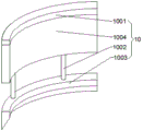
fig. 4 is a schematic view of the three-dimensional structure of the mud scraper of the present invention.
In the figure: 1-stirring tank, 2-control box, 3-feeding port, 4-water inlet, 5-discharging port, 6-driving motor, 7-rotating shaft, 8-crushing device, 801-crushing rod, 802-crushing sheet, 9-stirring device, 901-stirring rod, 902-stirring hook, 10-mud scraping device, 1001-arc fixing frame, 1002-electric telescopic rod, 1003-arc scraping plate, 1004-baffle, 11-vibrating motor, 12-supporting leg, 13-non-slip mat, 14-fixing plate, 15-observation window, 16-supporting seat and 17-connecting bearing.
Detailed Description
Example 1
As shown in figures 1 to 4, the utility model discloses a concrete mixing device, which adopts the technical proposal that the concrete mixing device comprises a mixing tank 1 and a control box 2, one side of the mixing tank 1 is fixedly connected with the control box 2, the upper surface of the mixing tank 1 is provided with a feed inlet 3, one side of the feed inlet 3 is provided with a water inlet 4, the feed inlet and the water inlet 3 are convenient for directly adding materials and water into the mixing tank 1, the bottom of the mixing tank 1 is provided with a discharge outlet 5, after the concrete is completely and uniformly mixed, the discharge outlet 5 is opened to conveniently discharge the uniformly mixed concrete, the upper surface of the mixing tank 1 is fixedly connected with a driving motor 6, the output end of the driving motor 6 is fixedly connected with a rotating shaft 7, the driving motor 6 drives the rotating shaft 7 to rotate, and simultaneously the rotating shaft 7 drives a crushing device 8 and a mixing device 9 to synchronously work, smash and stir the misce bene, the surface of pivot 7 is fixedly connected with reducing mechanism 8 and agitating unit 9 from the top down in proper order, and after reducing mechanism 8 and agitating unit 9 began to work, reducing mechanism 8 can smash the stone that gets into agitator tank 1 from feed inlet 3, avoids the stone of knoing or great stone to block agitator unit 8, and agitator unit 9 stirs the misce bene fully evenly, the inner wall of agitator tank 1 is provided with scrapes mud device 10, and after the concrete that mixes the stirring when complete discharge from bin outlet 5, opens scrapes mud device 10, can clear up the inner wall of agitator tank 1, scrapes the adnexed concrete of agitator tank 1 inner wall, one side fixedly connected with vibrating motor 11 of agitator tank 1, when discharging the concrete that mixes the stirring, can open vibrating motor 11, provides the vibrational force, the discharge rate of concrete is improved, the blocking condition is avoided, and the control box 2, the driving motor 6 and the vibrating motor 11 are electrically connected.
As the utility model discloses an optimal technical scheme, the lower fixed surface of agitator tank 1 is connected with landing leg 12, the lower fixed surface of landing leg 12 is connected with slipmat 13, stirs when smashing in agitator tank 1 at the mixed material, and landing leg 12 supports whole agitator tank 1, improves stability, and slipmat 13 avoids agitator tank 1 to take place to slide with ground.
As an optimal technical scheme of the utility model, the equal fixedly connected with fixed plate 14 of lower surface of control box 2 and vibrating motor 11, agitator tank 1's front is provided with observation window 15, and fixed plate 14 provides the holding power for control box 2 and vibrating motor 11's bottom, improves its stability, when the mixing material when the stirring is smashed, can observe stirring condition and effect through observation window 15.
As an optimal technical scheme of the utility model, inner diapire fixedly connected with supporting seat 16 of agitator tank 1, pivot 7 is through connecting bearing 17 and 16 swing joint of supporting seat, and when pivot 7 rotated, connecting bearing 17 and supporting seat 16 carried on spacingly to pivot 7, avoided pivot 7 to take place the skew.
As a preferred technical scheme of the utility model, reducing mechanism 8 includes crushing pole 801 and crushing piece 802, the outer fixed surface of pivot 7 is connected with crushing pole 801, a plurality of crushing pieces 802 of outer fixed surface of crushing pole 801, when pivot 7 rotates, crushing pole 801 and crushing piece 802 are also taken synchronous rotation, and the stone of adding agitator tank 1 can be smashed by crushing pole 801 and crushing piece 802 to avoid the stone of knoing or great stone to block agitating unit 9.
As an optimal technical scheme of the utility model, agitating unit 9 includes puddler 901 and stirring hook 902, the outer fixed surface of pivot 7 is connected with puddler 901, the one end fixedly connected with stirring hook 902 of puddler 901, when pivot 7 rotates, puddler 901 and stirring hook 902 are also taken synchronous rotation, and the mixing material of agitator tank 1 inside can be stirred the misce bene, has improved stirring efficiency.
As a preferred technical scheme of the utility model, the mud scraping device 10 comprises an arc-shaped fixing frame 1001, an electric telescopic rod 1002, an arc-shaped scraper 1003 and a baffle 1004, the inner wall of the stirring tank 1 is fixedly connected with the arc-shaped fixing frame 1001, the outer surface of the arc-shaped fixing frame 1001 is fixedly connected with the electric telescopic rod 1002, one end of the electric telescopic rod 1002 is fixedly connected with the arc-shaped scraper 1003, the electric telescopic rod 1002 is electrically connected with the control box 2, the upper surface of the fixing frame 1001 is fixedly connected with the baffle 1004, one end of the baffle 1004 is movably connected with the electric telescopic rod 1002 through a rubber sealing ring, when the uniformly mixed and stirred concrete is completely discharged from the discharge port 5, the mud scraping device 10 is opened, the electric telescopic rod 1002 can drive the arc-shaped scraper 1003 to move along the inner wall of the stirring tank 1, so as to clean the inner wall of the stirring tank 1 and scrape the concrete attached to the inner wall of the stirring tank 1, and meanwhile, the electric telescopic rod 1002 is prevented from being blocked by concrete.
The utility model discloses a theory of operation: firstly, a driving motor 6 is opened, materials and water are respectively added into a stirring tank 1 from a feed inlet 3 and a water inlet 4, when a rotating shaft 7 rotates, a crushing rod 801 and a crushing sheet 802 are also driven to synchronously rotate, stones added into the stirring tank 1 can be crushed by the crushing rod 801 and the crushing sheet 802, so that the phenomenon that knotted stones or larger stones block a stirring device 9 is avoided, when the rotating shaft 7 rotates, a stirring rod 901 and a stirring hook 902 are also driven to synchronously rotate, mixed materials in the stirring tank 1 can be uniformly stirred and mixed, the stirring efficiency is improved, then the stirring condition and the effect of concrete are observed from the outside through an observation window 15, when the concrete is completely and uniformly mixed, a discharge outlet 5 and a vibration motor 11 are opened to discharge the concrete, the vibration motor 11 provides vibration force, the discharge speed of the concrete is improved, the blockage condition is avoided, when the concrete which is uniformly mixed and stirred is completely discharged from the discharge outlet 5, open mud scraping device 10, electric telescopic handle 1002 can drive arc scraper 1003 and remove along 1 inner wall of agitator tank to clear up the inner wall of agitator tank 1, scrape the adnexed concrete of 1 inner wall of agitator tank.
The circuit connection of the present invention is a conventional method adopted by those skilled in the art, and can be suggested by limited tests, which belongs to the common knowledge.
Components not described in detail herein are prior art.
Although the present invention has been described in detail with reference to the specific embodiments, the present invention is not limited to the above embodiments, and various changes can be made without departing from the spirit of the present invention within the knowledge range of those skilled in the art, and modifications or variations without creative efforts are still within the scope of the present invention.
Claims (7)
1. The utility model provides a concrete mixing device, includes agitator tank (1) and control box (2), one side fixedly connected with control box (2) of agitator tank (1), feed inlet (3) have been seted up to the upper surface of agitator tank (1), one side of feed inlet (3) is provided with water inlet (4), bin outlet (5), its characterized in that have been seted up to the bottom of agitator tank (1): the last fixed surface of agitator tank (1) is connected with driving motor (6), the output fixedly connected with pivot (7) of driving motor (6), the surface from the top down of pivot (7) is fixedly connected with reducing mechanism (8) and agitating unit (9) in proper order, the inner wall of agitator tank (1) is provided with scrapes mud device (10), one side fixedly connected with vibrating motor (11) of agitator tank (1), equal electric connection between control box (2), driving motor (6) and vibrating motor (11).
2. A concrete mixing apparatus according to claim 1, wherein: the lower surface of agitator tank (1) is fixed with landing leg (12), the lower surface fixed connection of landing leg (12) has slipmat (13).
3. A concrete mixing apparatus according to claim 1, wherein: the lower surface of control box (2) and vibrating motor (11) is equal fixedly connected with fixed plate (14), the front of agitator tank (1) is provided with observation window (15).
4. A concrete mixing apparatus according to claim 1, wherein: the inner bottom wall of the stirring tank (1) is fixedly connected with a supporting seat (16), and the rotating shaft (7) is movably connected with the supporting seat (16) through a connecting bearing (17).
5. A concrete mixing apparatus according to claim 1, wherein: the crushing device (8) comprises a crushing rod (801) and crushing pieces (802), the outer surface of the rotating shaft (7) is fixedly connected with the crushing rod (801), and the outer surface of the crushing rod (801) is fixedly connected with a plurality of crushing pieces (802).
6. A concrete mixing apparatus according to claim 1, wherein: the stirring device (9) comprises a stirring rod (901) and a stirring hook (902), the stirring rod (901) is fixedly connected to the outer surface of the rotating shaft (7), and the stirring hook (902) is fixedly connected to one end of the stirring rod (901).
7. A concrete mixing apparatus according to claim 1, wherein: mud scraping device (10) include arc mount (1001), electric telescopic handle (1002), arc scraper blade (1003) and baffle (1004), the inner wall fixedly connected with arc mount (1001) of agitator tank (1), the outer fixed surface of arc mount (1001) is connected with electric telescopic handle (1002), the one end fixedly connected with arc scraper blade (1003) of electric telescopic handle (1002), electric telescopic handle (1002) and control box (2) electric connection, the last fixed surface of mount (1001) is connected with baffle (1004), rubber seal and electric telescopic handle (1002) swing joint are passed through to the one end of baffle (1004).
Priority Applications (1)
| Application Number | Priority Date | Filing Date | Title |
|---|---|---|---|
| CN202121273551.7U CN215282637U (en) | 2021-06-08 | 2021-06-08 | Concrete mixing device |
Applications Claiming Priority (1)
| Application Number | Priority Date | Filing Date | Title |
|---|---|---|---|
| CN202121273551.7U CN215282637U (en) | 2021-06-08 | 2021-06-08 | Concrete mixing device |
Publications (1)
| Publication Number | Publication Date |
|---|---|
| CN215282637U true CN215282637U (en) | 2021-12-24 |
Family
ID=79514774
Family Applications (1)
| Application Number | Title | Priority Date | Filing Date |
|---|---|---|---|
| CN202121273551.7U Active CN215282637U (en) | 2021-06-08 | 2021-06-08 | Concrete mixing device |
Country Status (1)
| Country | Link |
|---|---|
| CN (1) | CN215282637U (en) |
-
2021
- 2021-06-08 CN CN202121273551.7U patent/CN215282637U/en active Active
Similar Documents
| Publication | Publication Date | Title |
|---|---|---|
| CN210999358U (en) | Cement mixing plant for construction | |
| CN208359079U (en) | A kind of blender for concrete mixing plant | |
| CN209423518U (en) | A kind of chemical industry measurement mixing plant | |
| CN109464947A (en) | A kind of agitating device for geotechnical engineering construction | |
| CN215282637U (en) | Concrete mixing device | |
| CN208068576U (en) | Concrete mixer | |
| CN208005972U (en) | A kind of concrete mixer | |
| CN208100751U (en) | A kind of building concrete blender | |
| CN216299670U (en) | High-efficient mixer | |
| CN217346031U (en) | Concrete mixer convenient to inside is clean | |
| CN213198232U (en) | Water conservancy construction concrete agitator | |
| CN213918909U (en) | Building cement mortar mixing equipment | |
| CN210651294U (en) | High-efficient concrete mixing device is used in water conservancy construction | |
| CN111589337A (en) | Emulsification-balanced oil powder production device | |
| CN208215672U (en) | A kind of Building class material-stirring device | |
| CN212385700U (en) | Mortar mixer | |
| CN214459366U (en) | Highway construction is with batching agitated vessel | |
| CN212283740U (en) | Emulsification-balanced oil powder production device | |
| CN219634155U (en) | Stirring kettle | |
| CN219726725U (en) | Premixing equipment for concrete production and processing | |
| CN220638405U (en) | Anti-blocking concrete mixer | |
| CN214598755U (en) | Civil engineering rabbling mechanism | |
| CN219235708U (en) | Cement stirring device convenient to discharge | |
| CN220008278U (en) | Building compounding device | |
| CN209504518U (en) | A kind of agitating device of blender |
Legal Events
| Date | Code | Title | Description |
|---|---|---|---|
| GR01 | Patent grant | ||
| GR01 | Patent grant |