CN213913805U - High-efficient stirring reation kettle that chemical industry field was used - Google Patents
High-efficient stirring reation kettle that chemical industry field was used Download PDFInfo
- Publication number
- CN213913805U CN213913805U CN202022944912.8U CN202022944912U CN213913805U CN 213913805 U CN213913805 U CN 213913805U CN 202022944912 U CN202022944912 U CN 202022944912U CN 213913805 U CN213913805 U CN 213913805U
- Authority
- CN
- China
- Prior art keywords
- stirring
- reaction kettle
- wall
- plate
- kettle main
- Prior art date
- Legal status (The legal status is an assumption and is not a legal conclusion. Google has not performed a legal analysis and makes no representation as to the accuracy of the status listed.)
- Active
Links
Images


Landscapes
- Physical Or Chemical Processes And Apparatus (AREA)
Abstract
The utility model discloses a high-efficient stirring reation kettle that chemical industry field was used, including the reation kettle main part, the inner wall both sides of reation kettle main part all are equipped with the inlet pipe, the top of reation kettle main part is fixed with the footstock, install driving motor on the interior roof of footstock, fixedly connected with pivot on driving motor's the output shaft, the lower extreme of pivot extends to the inside of reation kettle main part, and install a plurality of first stirring boards and a plurality of second stirring board, the bottom welding of pivot has the arc, circumference equidistance is connected with a plurality of stirring pieces on the diapire of arc, the lead screw is all installed in the rotation of the inner wall both sides of footstock, the one end that two lead screws are close to each other all is fixed with first conical gear, the meshing has second conical gear on two first conical gear, second conical gear is fixed in the outside of driving motor output shaft. The utility model provides the high stirring effect of material, stir ground more thoroughly, increase the mixing efficiency of material, degree of automation is high, simple and practical is fit for promoting.
Description
Technical Field
The utility model relates to a reation kettle technical field especially relates to a high-efficient stirring reation kettle that chemical industry field was used.
Background
The reaction kettle is widely applied to pressure vessels for petroleum, chemical engineering, rubber, pesticides, dyes, medicines and foods, and is used for completing technological processes such as vulcanization, nitration, hydrogenation, alkylation, polymerization, condensation and the like, such as a reactor, a reaction kettle, a decomposition kettle, a polymerization kettle and the like; the material is generally carbon manganese steel, stainless steel, zirconium, nickel-based (Hastelloy, Monel, Inconel) alloy and other composite materials.
At present the stirring reation kettle that chemical industry field was used, the structure is too single, and reaction efficiency and effect are not very ideal, lead to the material in time misce bene, and the reaction is abundant inadequately to influence the quality of product, for this reason the utility model provides a high-efficient stirring reation kettle that chemical industry field was used.
SUMMERY OF THE UTILITY MODEL
The utility model aims at solving the problem that the reaction efficiency and the effect are not ideal in the prior art, leading to the material problem of in time misce bene, and the high-efficient stirring reation kettle who provides a chemical industry field is used.
In order to achieve the above purpose, the utility model adopts the following technical scheme:
a high-efficiency stirring reaction kettle used in the chemical field comprises a reaction kettle main body, wherein inlet pipes are assembled on two sides of the inner wall of the reaction kettle main body, a top seat is fixed at the top of the reaction kettle main body, a driving motor is installed on the inner top wall of the top seat, a rotating shaft is fixedly connected onto an output shaft of the driving motor, the lower end of the rotating shaft extends into the reaction kettle main body, and a plurality of first stirring plates and a plurality of second stirring plates are installed, an arc-shaped plate is welded at the bottom of the rotating shaft, a plurality of stirring blocks are connected onto the bottom wall of the arc-shaped plate at equal intervals in the circumferential direction, lead screws are rotatably installed on two sides of the inner wall of the top seat, a first conical gear is fixed at one end of each two lead screws close to each other, a second conical gear is meshed with the two first conical gears, the second conical gear is fixed outside the output shaft of the driving motor, and a pressing plate is sleeved with one end thread of each lead screw, the both ends of clamp plate sliding connection have the limiting plate respectively, the side of clamp plate is provided with the elasticity gasbag, and the one end of elasticity gasbag assembles on the inner wall of footstock, be connected with the outlet duct on the inner wall of elasticity gasbag, the lower extreme of outlet duct extends to the inside of reation kettle main part to fixedly connected with goes out the gas hood.
Preferably, the one end of limiting plate is fixed mutually with the inner wall of footstock, and the one end that two limiting plates are relative all is equipped with the spout, the both ends of clamp plate extend to the inside of two spouts respectively to be connected with the inner wall cooperation of spout.
Preferably, the length of first stirring board is greater than the length of second stirring board, and a plurality of first stirring boards all are the wave structure, and the second stirring board is located between two first stirring boards.
Preferably, a plurality of discharge holes are arranged on the arc plate at equal intervals, a discharge pipe is installed on the inner bottom wall of the reaction kettle main body, and a valve is assembled on the discharge pipe.
Preferably, the outer wall both sides of reation kettle main part all are equipped with the supporting leg, and sealing door is installed in the cooperation of the front of reation kettle main part.
Preferably, two gas outlet hoods are positioned above the plurality of first stirring plates and the plurality of second stirring plates.
Compared with the prior art, the utility model provides a high-efficient stirring reation kettle that chemical industry field was used possesses following beneficial effect:
1. through being provided with inlet pipe, reation kettle main part, driving motor, pivot, a plurality of first stirring board, a plurality of second stirring board and arc, a plurality of second stirring boards and arc mix the material for the reaction rate of material, arc and a plurality of stirring piece mix the stirring to the material of reation kettle main part bottom, have improved the stirring effect of material, stir ground more thoroughly.
2. Through being provided with driving motor, first bevel gear, two second bevel gears, two lead screws, clamp plate, elasticity gasbag, outlet duct and play gas cap, the inside of the reation kettle main part is impressed to gas in the elasticity gasbag, and gas carries out the inside of liquid material and carries out the tympanic bulla to increase the mixing efficiency of material, degree of automation is high, and is simple and practical, is fit for promoting.
Drawings
FIG. 1 is a schematic view of a cross-sectional structure of a high-efficiency stirred tank reactor for chemical engineering field;
FIG. 2 is a schematic view of a high-efficiency stirred tank reactor for chemical engineering field;
FIG. 3 is an enlarged view of a portion A of FIG. 1;
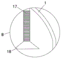
fig. 4 is a schematic view of a part of the enlarged structure at B in fig. 1.
In the figure: 1. a reaction kettle main body; 2. a feed pipe; 3. a top seat; 4. a drive motor; 5. a rotating shaft; 6. a first stirring plate; 7. a second stirring plate; 8. an arc-shaped plate; 9. stirring blocks; 10. a discharge pipe; 11. a second bevel gear; 12. a first bevel gear; 13. a limiting plate; 14. a screw rod; 15. pressing a plate; 16. an elastic air bag; 17. an air outlet pipe; 18. an air outlet cover; 19. and (4) sealing the door.
Detailed Description
The technical solutions in the embodiments of the present invention will be described clearly and completely with reference to the accompanying drawings in the embodiments of the present invention, and it is obvious that the described embodiments are only some embodiments of the present invention, not all embodiments.
In the description of the present invention, it is to be understood that the terms "upper", "lower", "front", "rear", "left", "right", "top", "bottom", "inner", "outer", and the like indicate orientations or positional relationships based on the orientations or positional relationships shown in the drawings, and are only for convenience of description and simplicity of description, and do not indicate or imply that the device or element being referred to must have a particular orientation, be constructed and operated in a particular orientation, and therefore, should not be construed as limiting the present invention.
Referring to fig. 1-4, a high-efficiency stirring reaction kettle for the chemical field comprises a reaction kettle main body 1, wherein a feeding pipe 2 is assembled on both sides of the inner wall of the reaction kettle main body 1, a top seat 3 is fixed on the top of the reaction kettle main body 1, a driving motor 4 is installed on the inner top wall of the top seat 3, a rotating shaft 5 is fixedly connected on the output shaft of the driving motor 4, the lower end of the rotating shaft 5 extends into the reaction kettle main body 1 and is provided with a plurality of first stirring plates 6 and a plurality of second stirring plates 7, an arc plate 8 is welded at the bottom of the rotating shaft 5, a plurality of stirring blocks 9 are connected on the bottom wall of the arc plate 8 at equal intervals in the circumferential direction, lead screws 14 are rotatably installed on both sides of the inner wall of the top seat 3, a first bevel gear 12 is fixed on one end of the two lead screws 14 close to each other, a second bevel gear 11 is meshed on the two first bevel gears 12, the second bevel gear 11 is fixed outside the output shaft of the driving motor 4, a pressing plate 15 is sleeved at one end of the screw rod 14 in a threaded manner, limiting plates 13 are respectively connected to two ends of the pressing plate 15 in a sliding manner, an elastic air bag 16 is arranged on the side surface of the pressing plate 15, one end of the elastic air bag 16 is assembled on the inner wall of the top seat 3, an air outlet pipe 17 is connected to the inner wall of the elastic air bag 16, the lower end of the air outlet pipe 17 extends to the inside of the reaction kettle main body 1 and is fixedly connected with an air outlet cover 18, and the air outlet cover 18 is arranged inside the liquid material, so that external gas can be introduced into the material, the disturbance of the liquid material is increased, and the mixing efficiency is improved; it is worth to be noted that the elastic air bag 16 is provided with an air inlet connector, the air inlet connector is provided with a one-way air inlet valve, the air outlet pipe 17 is provided with a one-way air outlet valve, and the lower end of the air outlet pipe 17 is made of a corrugated pipe.
In this embodiment, the one end of limiting plate 13 is fixed mutually with the inner wall of footstock 3, and the one end that two limiting plates 13 are relative all is equipped with the spout, the both ends of clamp plate 15 extend to the inside of two spouts respectively to be connected with the inner wall cooperation of spout.
In this embodiment, the length of the first stirring plate 6 is greater than that of the second stirring plate 7, the first stirring plates 6 are all in a wave-shaped structure, and the second stirring plate 7 is located between the two first stirring plates 6.
In this embodiment, a plurality of discharge holes are arranged on the arc plate 8 at equal distances, a discharge pipe 10 is installed on the inner bottom wall of the reaction kettle main body 1, and a valve is installed on the discharge pipe 10.
In this embodiment, the outer wall both sides of reation kettle main part 1 all are equipped with the supporting leg, and sealing door 19 is installed in the cooperation of the front of reation kettle main part 1.
In this embodiment, two of the gas outlet covers 18 are located above the plurality of first agitating plates 6 and the plurality of second agitating plates 7.
In the utility model, when in use, chemical raw materials and water are firstly added into the reaction kettle main body 1 through the feeding pipe 2, the materials are mixed by starting the driving motor 4 to work, the rotating shaft 5, the first stirring plates 6, the second stirring plates 7 and the arc-shaped plate 8 are driven by the driving motor 4 to rotate, the materials are mixed by the second stirring plates 7 and the arc-shaped plate 8, the reaction speed of the materials is accelerated, the arc-shaped plate 8 drives the stirring blocks 9 to rotate, the materials at the bottom of the reaction kettle main body 1 are mixed and stirred, the stirring effect of the materials is improved, the materials are stirred more thoroughly, the driving motor 4 drives the first bevel gear 12 to rotate while rotating, the first bevel gear 12 drives the two second bevel gears 11 to rotate, the two lead screws 14 are respectively driven to rotate when the two second bevel gears 11 rotate, the pressing plate 15 is driven to move left and right when the two lead screws 14 rotate, the clamp plate 15 is pressed on the elastic air bag 16, the gas in the elastic air bag 16 is pressed into the reaction kettle main body 1, and the gas is bubbled in the liquid material, so that the mixing efficiency of the material is increased, the degree of automation is high, and the device is simple, practical and suitable for popularization.
The above, only be the concrete implementation of the preferred embodiment of the present invention, but the protection scope of the present invention is not limited thereto, and any person skilled in the art is in the technical scope of the present invention, according to the technical solution of the present invention and the utility model, the concept of which is equivalent to replace or change, should be covered within the protection scope of the present invention.
Claims (6)
1. The high-efficiency stirring reaction kettle comprises a reaction kettle main body (1) and is characterized in that an inlet pipe (2) is assembled on the two sides of the inner wall of the reaction kettle main body (1), a top seat (3) is fixed at the top of the reaction kettle main body (1), a driving motor (4) is installed on the inner top wall of the top seat (3), a rotating shaft (5) is fixedly connected onto the output shaft of the driving motor (4), the lower end of the rotating shaft (5) extends into the reaction kettle main body (1), a plurality of first stirring plates (6) and a plurality of second stirring plates (7) are installed, an arc-shaped plate (8) is welded at the bottom of the rotating shaft (5), a plurality of stirring blocks (9) are connected onto the bottom wall of the arc-shaped plate (8) at equal intervals in the circumferential direction, screw rods (14) are installed on the two sides of the inner wall of the top seat (3) in a rotating manner, and first conical gears (12) are fixed at one ends, close to each other, of the two screw rods (14), the meshing has second bevel gear (11) on two first bevel gear (12), second bevel gear (11) are fixed in the outside of driving motor (4) output shaft, clamp plate (15) have been cup jointed to the one end screw thread of lead screw (14), and there are limiting plate (13) at the both ends difference sliding connection of clamp plate (15), the side of clamp plate (15) is provided with elasticity gasbag (16), and the one end of elasticity gasbag (16) assembles on the inner wall of footstock (3), be connected with outlet duct (17) on the inner wall of elasticity gasbag (16), the lower extreme of outlet duct (17) extends to the inside of reation kettle main part (1) to fixedly connected with goes out gas hood (18).
2. The high-efficiency stirring reaction kettle for the chemical field according to claim 1, wherein one end of the limiting plate (13) is fixed to the inner wall of the top seat (3), the opposite ends of the two limiting plates (13) are provided with sliding grooves, and the two ends of the pressing plate (15) respectively extend into the two sliding grooves and are connected with the inner wall of the sliding grooves in a matching manner.
3. The high-efficiency stirring reaction kettle for the chemical field according to claim 1, wherein the length of the first stirring plate (6) is greater than that of the second stirring plate (7), the first stirring plates (6) are all in a wave-shaped structure, and the second stirring plate (7) is located between the two first stirring plates (6).
4. The stirring reaction kettle as claimed in claim 1, wherein the arc plate (8) has a plurality of discharging holes at equal intervals, a discharging pipe (10) is installed on the inner bottom wall of the reaction kettle body (1), and a valve is installed on the discharging pipe (10).
5. The high-efficiency stirring reaction kettle for the chemical field is characterized in that supporting legs are arranged on two sides of the outer wall of the reaction kettle main body (1), and a sealing door (19) is arranged on the front face of the reaction kettle main body (1) in a matching mode.
6. The stirred tank reactor of claim 1, wherein the two gas outlet hoods (18) are located above the first stirring plate (6) and the second stirring plate (7).
Priority Applications (1)
| Application Number | Priority Date | Filing Date | Title |
|---|---|---|---|
| CN202022944912.8U CN213913805U (en) | 2020-12-11 | 2020-12-11 | High-efficient stirring reation kettle that chemical industry field was used |
Applications Claiming Priority (1)
| Application Number | Priority Date | Filing Date | Title |
|---|---|---|---|
| CN202022944912.8U CN213913805U (en) | 2020-12-11 | 2020-12-11 | High-efficient stirring reation kettle that chemical industry field was used |
Publications (1)
| Publication Number | Publication Date |
|---|---|
| CN213913805U true CN213913805U (en) | 2021-08-10 |
Family
ID=77150592
Family Applications (1)
| Application Number | Title | Priority Date | Filing Date |
|---|---|---|---|
| CN202022944912.8U Active CN213913805U (en) | 2020-12-11 | 2020-12-11 | High-efficient stirring reation kettle that chemical industry field was used |
Country Status (1)
| Country | Link |
|---|---|
| CN (1) | CN213913805U (en) |
-
2020
- 2020-12-11 CN CN202022944912.8U patent/CN213913805U/en active Active
Similar Documents
| Publication | Publication Date | Title |
|---|---|---|
| CN211159730U (en) | Vertical circulation reation kettle | |
| CN213966590U (en) | Reation kettle that mixing effect is good | |
| CN207805629U (en) | A kind of swing solid-liquid reaction kettle | |
| CN213913805U (en) | High-efficient stirring reation kettle that chemical industry field was used | |
| CN211936885U (en) | Reaction unit with impulse type agitator | |
| CN210874981U (en) | Chemical industry reation kettle's premixing device | |
| CN211754948U (en) | Reation kettle for chemical industry convenient to wash inner wall | |
| CN208436676U (en) | A kind of highly effective reaction kettle agitating paddle | |
| CN215353401U (en) | A high-efficient reation kettle for pesticide production | |
| CN215028900U (en) | High-purity terpineol reaction kettle | |
| CN213669261U (en) | Energy-saving chemical industry reation kettle | |
| CN213995849U (en) | Mixed heating type chemical reaction kettle | |
| CN211636514U (en) | Conveniently unpack apart clear chemical industry reation kettle | |
| CN207981190U (en) | A kind of reaction kettle with agitating function | |
| CN213699836U (en) | Take cleaning function's chemical industry reation kettle | |
| CN208583348U (en) | A kind of petrochemical industry reaction kettle | |
| CN220425353U (en) | Reation kettle convenient to keep pressure | |
| CN207655117U (en) | A kind of concentration kettle for producing sildenafil intermediate | |
| CN211660004U (en) | High-efficient reation kettle | |
| CN215312337U (en) | Reation kettle for chemical industry of stirring | |
| CN216367947U (en) | Chemical industry reation kettle that high-efficient reaction is even | |
| CN214346455U (en) | Chemical production uses high-efficient reation kettle | |
| CN218281682U (en) | Vacuum reaction kettle capable of avoiding residual materials on inner wall | |
| CN211988566U (en) | Glass lining reaction tank | |
| CN215429021U (en) | Energy-concerving and environment-protective reation kettle for chemical industry |
Legal Events
| Date | Code | Title | Description |
|---|---|---|---|
| GR01 | Patent grant | ||
| GR01 | Patent grant |