CN213905022U - Automatic cable wire bunching device - Google Patents
Automatic cable wire bunching device Download PDFInfo
- Publication number
- CN213905022U CN213905022U CN202023207581.6U CN202023207581U CN213905022U CN 213905022 U CN213905022 U CN 213905022U CN 202023207581 U CN202023207581 U CN 202023207581U CN 213905022 U CN213905022 U CN 213905022U
- Authority
- CN
- China
- Prior art keywords
- plate
- straightening
- wire
- rod
- moving
- Prior art date
- Legal status (The legal status is an assumption and is not a legal conclusion. Google has not performed a legal analysis and makes no representation as to the accuracy of the status listed.)
- Active
Links
Images


Abstract
The utility model provides an automatic cable wire bunching device in the technical field of cable wire production equipment, which comprises a frame, a support plate is arranged on the frame, a straightening mechanism and a shearing mechanism are arranged on the support plate, the straightening mechanism comprises a plurality of lower straightening rollers which are rotatably arranged on the support plate, a straightening plate which can move up and down is connected on the support plate above the lower straightening rollers, a plurality of upper straightening rollers are rotatably arranged on the straightening plate, a wire supply reel is arranged on the frame outside the straightening mechanism, the shearing mechanism comprises a cutter holder with a cutting groove, two blades which can move up and down are arranged on the cutter holder, a conveying mechanism is arranged on the support plate between the shearing mechanism and the straightening mechanism, the conveying mechanism comprises a driving wheel which is rotatably connected on the support plate, a lifting plate which can move up and down is also connected on the support plate, a driven wheel is rotatably connected on the lifting plate, the driven wheel is arranged right above the driving wheel; the utility model discloses work is convenient, and work efficiency is high.
Description
Technical Field
The utility model belongs to the technical field of cable wire production facility, in particular to automatic bunching device of cable wire.
Background
The cable comprises a power cable, a control cable, a compensation cable, a shielding cable, a high-temperature cable, a computer cable, a signal cable, a coaxial cable, a fire-resistant cable, a marine cable, an aluminum alloy cable and the like, which are all composed of single-stranded or multi-stranded wires and insulating layers, wherein each group of wires are mutually insulated, usually twisted around a center, and covered with a highly insulating covering layer, the production and manufacture of the cable are generally completed by three processes of drawing, stranding and covering, in the production process of the cable, a plurality of production devices are used, and all levels of treatment such as winding machine, shearing machine, packaging and the like are needed, in the process of producing cables of different types, wires are often required to be cut so as to meet the cable lengths required by different occasions and types, and in the stranding stage, a bunching machine or a stranding machine is used for stranding the stretched multi-strand wires into wire cores of various wire cables with different specifications and sections.
Among the prior art, the cable wire of overlength twines easily, and is unordered in a jumble, occupies great storage space to need cut cable wire and bunch, current cable wire cuts mechanism single structure, adopts the manual work to tailor mostly, and wire winding and bunch are pleasing to the eye, and work is inconvenient, and work efficiency is low.
SUMMERY OF THE UTILITY MODEL
To the defect among the prior art, the utility model discloses an aim at solves the weak point among the prior art, has solved the technical problem that work is inconvenient among the prior art, and work efficiency is low, provides an automatic bunching device of cable wire, and this device work is convenient, and work efficiency is high.
The purpose of the utility model is realized like this: an automatic cable wire bunching device comprises a rack, wherein a support plate is arranged on the rack, a straightening mechanism and a shearing mechanism are arranged on the support plate, the straightening mechanism comprises a plurality of lower straightening rollers which are rotatably arranged on the support plate, a straightening plate which can move up and down is connected on the support plate above the lower straightening rollers, a plurality of upper straightening rollers are rotatably arranged on the straightening plate, any upper straightening roller is arranged between the two lower straightening rollers, a wire supply reel is arranged on the rack outside the straightening mechanism, the shearing mechanism comprises a cutter holder with a cutting groove, two blades which can move up and down are arranged on the cutter holder, the two blades are oppositely arranged on the upper side and the lower side of the cutting groove, a conveying mechanism is arranged on the support plate between the shearing mechanism and the straightening mechanism, and the conveying mechanism comprises a driving wheel which is rotatably connected on the support plate, the wire binding machine is characterized in that a lifting plate capable of moving up and down is further connected to the supporting plate, a driven wheel is rotatably connected to the lifting plate, the driven wheel is located right above the driving wheel, a wire guide plate is arranged on the supporting plate between the conveying mechanism and the shearing mechanism, a wire guide groove is formed in the wire guide plate, wires between the driving wheel and the driven wheel can slide along the wire guide groove, a clamping mechanism is further arranged on the rack and comprises a lower moving plate capable of moving in the left-right direction, an upper moving plate capable of moving in the left-right direction is arranged on the moving plate, an openable clamping jaw is arranged on the upper moving plate, a wire binding mechanism is arranged on the rack between the supporting plate and the lower moving plate and comprises a moving platform capable of moving back and forth, two openable wire binding claws are connected to the moving platform, and the wires can move right above the two wire binding claws.
The utility model discloses before the work, the wire rod tractive in proper order on the supply spool passes between last leveling roller and the lower leveling roller, between action wheel and the driven wheel, and the metallic channel, adjust and go up the leveling roller and reciprocate, make the wire rod just be cliied by last leveling roller and lower leveling roller, adjust the action wheel and reciprocate, make the wire rod just be cliied by action wheel and driven wheel, in operation, the action wheel rotates, action wheel and driven wheel drive the wire rod and move right, the wire rod receives last leveling roller and lower leveling roller straightening effect, eliminate the unevenness on wire rod surface, receive the guide effect of metallic channel, the wire rod moves right and passes the cutting groove, when the wire rod moves right to a certain distance, move down the movable plate and move one section distance left again on, the clamping jaw is opened the back closure (the clamping jaw is prior art, how the clamping jaw realizes opening and shutting, the utility model discloses no longer repeated description), the wire rod is clamped, the lower moving plate moves rightwards, when the required length of the wire rod is reached, the manipulator clamps the wound cable and just moves to the position above the wire rod and moves downwards, the shearing mechanism works, the two blades move relatively to shear the wire rod, meanwhile, the clamping jaw is opened, the two bunching claws are opened, the manipulator drives the cable to press down the sheared wire rod and moves downwards to the two bunching claws, the two bunching claws are closed again, the moving platform drives the bunched cable to move backwards to the next processing unit, and workers perform manual bundling or manipulator bundling (the manipulator is in the prior art and is not shown in the attached drawings); compared with the prior art, the beneficial effects of the utility model reside in that: the straightening mechanism of the utility model eliminates the unevenness of the surface of the wire rod, and the bunching product is beautiful; due to the arrangement of the shearing mechanism and the clamping mechanism, the wire rod is automatically sheared, the working efficiency is high, and the use is convenient; due to the arrangement of the conveying mechanism, the wire rods are automatically conveyed, and the working efficiency is high; the arrangement of the wire bundling mechanism can automatically wrap the cable with the wire for bundling, and the cable is transferred to the next stage of station for bundling, so that the working efficiency is high; the utility model discloses can be applied to the automatic bundling bunch work of cable.
In order to realize that the lower straightening roller and the upper straightening roller can straighten wires, a wire inlet rod is further arranged on the supporting plate outside the lower straightening roller, a wire inlet hole is formed in the wire inlet rod and is arranged between the lower straightening roller and the upper straightening roller, a first linear driver is arranged on the supporting plate, a straightening rod capable of moving up and down is arranged on the first linear driver, and the downward end of the straightening rod is connected with a straightening plate.
In order to realize that the blade can be connected to the blade holder in a sliding manner, the blade holder is further provided with two fixing plates, a sliding space is formed between the fixing plates and the blade holder, the blade is inserted into the sliding space, and the fixing plates are further provided with grooves.
In order to realize the up-and-down movement of the lifting plate, the conveying mechanism further comprises a second linear driver, a conveying rod capable of moving up and down is arranged on the second linear driver, the conveying rod is connected with the lifting plate, a driving motor is arranged on the supporting plate, and an output shaft of the driving motor is connected with a wheel shaft of the driving wheel.
In order to realize the left and right movement of the lower moving plate, the clamping mechanism further comprises a bottom plate arranged on the rack, a sliding rail and a linear driver III are arranged on the bottom plate, a pushing rod capable of reciprocating in the left and right directions is arranged on the linear driver III, the pushing rod is connected with the lower moving plate, a sliding block is connected onto the sliding rail in a sliding mode, and the lower moving plate is arranged on the sliding block.
In order to realize the left and right movement of the upper moving plate, the lower moving plate is provided with a connecting plate, the connecting plate is provided with a linear driver IV, the linear driver IV is provided with a pull rod capable of moving left and right, and a clamping jaw on the pull rod is connected with the pull rod.
In order to realize the front and back movement of the mobile station, the rack is also provided with a guide rail, the guide rail is connected with a guide block in a sliding manner, the mobile station is connected to the guide block, the rack is provided with a linear driver V, the linear driver V is provided with a guide rod capable of moving in the front and back direction, and the guide rod is connected with the mobile station.
In order to realize that bunch claw opens and shuts, be equipped with the supporting seat on the mobile station, bunch claw articulates on the supporting seat, the effect both sides of supporting seat are equipped with sharp driver six respectively, be equipped with the telescopic link on the sharp driver six, it has the hinge bar to articulate on the telescopic link, the hinge bar articulates on the bunch claw that corresponds.
In order to realize the shearing by moving the blade up and down, the shearing mechanism further comprises two guide rails arranged on the cutter holder, a driving plate is connected between the two guide rails in a sliding manner, two driving support plates are arranged at the forward end of the driving plate, a through groove communicated with the cutting groove is reserved between the two driving support plates, a sliding groove which is downwards inclined from front to back is formed in each driving support plate, an extending part which extends outwards and is inserted in the sliding groove is arranged on the blade, the extending part moves up and down along the opening groove when the driving plate moves back and forth, a linear driver seventh is further arranged on the cutter holder, a shearing rod which can move in the front and back direction is arranged on the linear driver seventh, and the shearing rod is connected with the driving plate.
Drawings
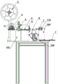
Fig. 1 is a front view of the present invention.
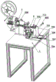
Fig. 2 is a first perspective view of the present invention.
Fig. 3 is a partially enlarged view of a portion a in fig. 2.
Fig. 4 is a partially enlarged view of fig. 2 at B.
Fig. 5 is a schematic structural diagram of the middle shearing mechanism of the present invention.
Fig. 6 is a schematic structural diagram of the middle shearing mechanism of the present invention.
Fig. 7 is a schematic structural view of fig. 6 with the drive plate removed.
In the figure: 1 rack, 101 supporting plate, 2 wire feeding reel, 3 straightening mechanism, 301 lower straightening roller, 302 straightening plate, 303 upper straightening roller, 304 wire feeding rod, 304a wire feeding hole, 305 linear driver I, 306 straightening rod, 4 shearing mechanism, 401 cutter seat, 401a cutting groove, 402 blade, 402a extending part, 403 fixing plate, 403a slotting, 404 sliding space, 405 guide rail, 406 driving plate, 407 driving support plate, 407a through groove, 407b sliding groove, 408 linear driver seven, 409 shearing rod, 5 conveying mechanism, 501 driving wheel, 502 lifting plate, 503 driven wheel, 504 linear driver II, 505 conveying rod, 506 driving motor, 6 wire guide plate, 601 wire guide groove, 7 clamping mechanism, 701 downward moving plate, 702 upper moving plate, clamping jaw 703, 704, bottom plate, 705 sliding rail, 706 linear driver III, pushing rod 707, 708 sliding block, 709 connecting plate, 710 linear driver IV, 711, 8 wire binding mechanism, the automatic wire winding machine comprises an 801 moving table, 802 wire bundling claws, 803 guide rails, 804 guide blocks, 805 linear drivers five, 806 guide rods, 807 supporting seats, 808 linear drivers six, 809 telescopic rods and 810 hinge rods.
Detailed Description
The present invention will be further described with reference to the accompanying drawings.
As shown in fig. 1 to 7, an automatic cable bunching device comprises a frame 1, a support plate 101 is arranged on the frame 1, a straightening mechanism 3 and a shearing mechanism 4 are arranged on the support plate 101, the straightening mechanism 3 comprises a plurality of lower straightening rollers 301 which are rotatably arranged on the support plate 101, a straightening plate 302 which can move up and down is connected on the support plate 101 above the lower straightening rollers 301, a plurality of upper straightening rollers 303 are rotatably arranged on the straightening plate 302, any upper straightening roller 303 is arranged between the two lower straightening rollers 301, a wire supply reel 2 is arranged on the frame 1 outside the straightening mechanism 3, the shearing mechanism 4 comprises a cutter holder 401 with a cutting groove 401a, two blades 402 which can move up and down are arranged on the cutter holder 401, the two blades 402 are oppositely arranged on the upper side and the lower side of the cutting groove 401a, a transmission mechanism 5 is arranged on the support plate 101 between the shearing mechanism 4 and the straightening mechanism 3, the conveying mechanism 5 comprises a driving wheel 501 rotatably connected to the supporting plate 101, the supporting plate 101 is further connected with a lifting plate 502 capable of moving up and down, the lifting plate 502 is rotatably connected with a driven wheel 503, the driven wheel 503 is arranged right above the driving wheel 501, a wire guide plate 6 is arranged on the supporting plate 101 between the conveying mechanism 5 and the shearing mechanism 4, a wire guide groove 601 is formed in the wire guide plate 6, a wire between the driving wheel 501 and the driven wheel 503 can slide along the wire guide groove 601, the frame 1 is further provided with a clamping mechanism 7, the clamping mechanism 7 comprises a lower moving plate 701 capable of moving in the left-right direction, an upper moving plate 702 capable of moving in the left-right direction is arranged on the moving plate, an openable clamping jaw 703 is arranged on the upper moving plate 702, a wire bundling mechanism 8 is arranged on the frame 1 between the supporting plate 101 and the lower moving plate 701, the wire bundling mechanism 8 comprises a moving platform 801 capable of moving back and forth, two openable clamping jaws 802 are connected on the moving platform 801, the wire can move right above the two bunching claws 802; a wire inlet rod 304 is further arranged on the support plate 101 on the outer side of the lower straightening roller 301, a wire inlet hole 304a is formed in the wire inlet rod 304, the wire inlet hole 304a is formed between the lower straightening roller 301 and the upper straightening roller 303, a first linear driver 305 is arranged on the support plate 101, a straightening rod 306 capable of moving up and down is arranged on the first linear driver 305, and the downward end of the straightening rod 306 is connected with the straightening plate 302; the tool apron 401 is further provided with two fixing plates 403, a sliding space 404 is formed between the fixing plates 403 and the tool apron 401, the blade 402 is inserted into the sliding space 404, and the fixing plates 403 are further provided with slots 403 a; the transmission mechanism 5 further comprises a second linear driver 504, a transmission rod 505 capable of moving up and down is arranged on the second linear driver 504, the transmission rod 505 is connected with the lifting plate 502, a driving motor 506 is arranged on the supporting plate 101, and an output shaft of the driving motor 506 is connected with a wheel shaft of the driving wheel 501; the clamping mechanism 7 further comprises a bottom plate 704 arranged on the frame 1, a sliding rail 705 and a linear driver III 706 are arranged on the bottom plate 704, a push rod 707 capable of reciprocating in the left-right direction is arranged on the linear driver III 706, the push rod 707 is connected with a lower moving plate 701, a sliding block 708 is connected to the sliding rail 705 in a sliding mode, and the lower moving plate 701 is arranged on the sliding block 708; the lower moving plate 701 is provided with a connecting plate 709, the connecting plate 709 is provided with a linear driver IV 710, the linear driver IV 710 is provided with a pull rod 711 capable of moving left and right, and the clamping jaw 703 on the pull rod 711 is connected with the pull rod 711; the rack 1 is also provided with a guide rail 803, the guide rail 803 is slidably connected with a guide block 804, the mobile platform 801 is connected with the guide block 804, the rack 1 is provided with a linear driver five 805, the linear driver five 805 is provided with a guide rod 806 capable of moving in the front-back direction, and the guide rod 806 is connected with the mobile platform 801; a support seat 807 is arranged on the mobile platform 801, the bunching claws 802 are hinged on the support seat 807, two sides of the support seat 807 in action are respectively provided with a linear driver six 808, the linear driver six 808 is provided with a telescopic rod 809, the telescopic rod 809 is hinged with a hinge rod 810, and the hinge rod 810 is hinged on the corresponding bunching claw 802; the shearing mechanism 4 further comprises two guide rails 405 arranged on the tool apron 401, a driving plate 406 is connected between the two guide rails 405 in a sliding manner, two driving support plates 407 are arranged at the forward end of the driving plate 406, a through groove 407a communicated with the cutting groove 401a is reserved between the two driving support plates 407, a sliding groove 407b which is obliquely arranged from front to back is formed in the driving support plates 407, an extending portion 402a which extends outwards and is inserted in the sliding groove 407b is arranged on the blade 402, when the driving plate 406 moves forwards and backwards, the extending portion 402a moves up and down along the opening groove 403a, a linear driver seven 408 is further arranged on the tool apron 401, a shearing rod 409 which can move in the front and back direction is arranged on the linear driver seven 408, and the shearing rod 409 is connected with the driving plate 406.
Before the utility model works, the wire on the wire supply reel 2 is sequentially pulled to pass between the upper straightening roll 303 and the lower straightening roll 301, between the driving wheel 501 and the driven wheel 503 and the wire groove 601, the straightening rod 306 of the first control linear driver 305 moves up and down to move the upper straightening roll 303 up and down until the wire is just clamped by the upper straightening roll 303 and the lower straightening roll 301, the transmission rod 505 of the second control linear driver 504 moves up and down to move the driving wheel 501 up and down until the wire is just clamped by the driving wheel 501 and the driven wheel 503, in work, the driving motor 506 drives the driving wheel 501 to rotate, the driving wheel 501 and the driven wheel 503 drive the wire to move rightwards, the wire is straightened by the upper straightening roll 303 and the lower straightening roll 301, the unevenness on the surface of the wire is eliminated, the wire is guided by the wire groove 601, the wire moves rightwards to pass through the cutting groove 401a, when the wire moves rightwards to a certain distance, the push rod 707 of the third linear actuator 706 moves leftwards, after the lower moving plate 701 moves leftwards for a certain distance, the pull rod 711 of the fourth linear actuator 710 moves leftwards, the upper moving plate 702 moves leftwards for a certain distance, the clamping jaw 703 opens and closes (the clamping jaw 703 is the prior art, how the clamping jaw 703 opens and closes, the utility model is not described any more), the wire is clamped, the push rod 707 of the third linear actuator 706 moves rightwards, the lower moving plate 701 moves rightwards, when the required length of the wire is reached, the manipulator clamps the wound cable and moves right above the wire and moves downwards, the shearing mechanism 4 works, the shearing rod 409 of the seventh linear actuator 408 extends forwards, the driving plate 406 moves forwards, the extension part 402a moves along the slot a, the two blades 402 move relatively, the wire is sheared, meanwhile, the clamping jaw 703 opens, the telescopic rod 809 of the sixth linear actuator 808 retracts, the hinged rod 810 drives the bunching claws 802 to open, the manipulator drives the cable to press down and cut wires to move downwards to the two bunching claws 802, the telescopic rod 809 of the linear driver six 808 drives the two bunching claws 802 to close again, the guide rod 806 of the linear driver five 805 drives the mobile platform 801 to move backwards, the mobile platform 801 drives the bunched cables to move backwards to the next processing unit, and manual bundling or manipulator bundling is performed by workers (the manipulator is in the prior art, and is not shown in the attached drawings); compared with the prior art, the beneficial effects of the utility model reside in that: the straightening mechanism 3 in the utility model eliminates the unevenness of the surface of the wire rod, and the bunching product is beautiful; due to the arrangement of the shearing mechanism 4 and the clamping mechanism 7, the wire rod is automatically sheared, the working efficiency is high, and the use is convenient; due to the arrangement of the conveying mechanism, the wire rods are automatically conveyed, and the working efficiency is high; the arrangement of the wire bundling mechanism 8 can automatically wrap the cable with the wire for bundling, and the cable is transferred to the next stage of station for bundling, so that the working efficiency is high; the utility model discloses can be applied to the automatic bundling bunch work of cable.
The present invention is not limited to the above embodiments, and based on the technical solutions disclosed in the present invention, those skilled in the art can make some replacements and transformations for some technical features without creative labor according to the disclosed technical contents, and these replacements and transformations are all within the protection scope of the present invention.
Claims (9)
1. An automatic cable wire bunching device is characterized by comprising a rack, wherein a support plate is arranged on the rack, a straightening mechanism and a shearing mechanism are arranged on the support plate, the straightening mechanism comprises a plurality of lower straightening rollers which are rotatably arranged on the support plate, a straightening plate which can move up and down is connected on the support plate above the lower straightening rollers, a plurality of upper straightening rollers are rotatably arranged on the straightening plate, any upper straightening roller is arranged between the two lower straightening rollers, a wire supply reel is arranged on the rack outside the straightening mechanism, the shearing mechanism comprises a cutter holder with a cutting groove, two blades which can move up and down are arranged on the cutter holder, the two blades are oppositely arranged on the upper side and the lower side of the cutting groove, a conveying mechanism is arranged on the support plate between the shearing mechanism and the straightening mechanism, and the conveying mechanism comprises a driving wheel which is rotatably connected on the support plate, the wire binding machine is characterized in that a lifting plate capable of moving up and down is further connected to the supporting plate, a driven wheel is rotatably connected to the lifting plate, the driven wheel is located right above the driving wheel, a wire guide plate is arranged on the supporting plate between the conveying mechanism and the shearing mechanism, a wire guide groove is formed in the wire guide plate, wires between the driving wheel and the driven wheel can slide along the wire guide groove, a clamping mechanism is further arranged on the rack and comprises a lower moving plate capable of moving in the left-right direction, an upper moving plate capable of moving in the left-right direction is arranged on the moving plate, an openable clamping jaw is arranged on the upper moving plate, a wire binding mechanism is arranged on the rack between the supporting plate and the lower moving plate and comprises a moving platform capable of moving back and forth, two openable wire binding claws are connected to the moving platform, and the wires can move right above the two wire binding claws.
2. The automatic cable bunching device as claimed in claim 1, wherein a wire inlet rod is further disposed on the support plate outside the lower straightening roller, a wire inlet hole is formed in the wire inlet rod, the wire inlet hole is formed between the lower straightening roller and the upper straightening roller, a first linear driver is disposed on the support plate, a straightening rod capable of moving up and down is disposed on the first linear driver, and a downward end of the straightening rod is connected with the straightening plate.
3. The automatic cable wire bunching device as claimed in claim 1, wherein the tool apron is further provided with two fixing plates, a sliding space is formed between the fixing plates and the tool apron, the blade is inserted into the sliding space, and the fixing plates are further provided with slots.
4. The automatic cable wire bunching device as claimed in claim 3, wherein the conveying mechanism further comprises a second linear driver, the second linear driver is provided with a conveying rod capable of moving up and down, the conveying rod is connected with the lifting plate, the supporting plate is provided with a driving motor, and an output shaft of the driving motor is connected with a wheel shaft of the driving wheel.
5. The automatic cable wire bunching device according to claim 4, wherein the clamping mechanism further comprises a bottom plate arranged on the frame, the bottom plate is provided with a slide rail and a third linear actuator, the third linear actuator is provided with a push rod capable of reciprocating in the left-right direction, the push rod is connected with a lower moving plate, the slide rail is slidably connected with a slide block, and the lower moving plate is arranged on the slide block.
6. The automatic cable wire bunching device as claimed in claim 5, wherein the lower movable plate is provided with a connecting plate, the connecting plate is provided with a linear actuator IV, the linear actuator IV is provided with a pull rod capable of moving left and right, and the pull rod is connected with a clamping jaw on the pull rod.
7. The automatic cable wire bunching device as claimed in claim 6, wherein the frame is further provided with a guide rail, the guide rail is slidably connected with a guide block, the moving platform is connected with the guide block, the frame is provided with a linear actuator V, the linear actuator V is provided with a guide rod capable of moving in the front-back direction, and the guide rod is connected with the moving platform.
8. The automatic cable wire bunching device as claimed in claim 7, wherein the movable platform is provided with a support base, the bunching claws are hinged to the support base, two sides of the support base are respectively provided with a linear driver six, the linear driver six is provided with a telescopic rod, the telescopic rod is hinged to a hinge rod, and the hinge rod is hinged to the corresponding bunching claw.
9. The automatic cable harness device according to claim 8, wherein the cutting mechanism further comprises two guide rails disposed on the cutter base, a driving plate is slidably connected between the two guide rails, two driving support plates are disposed at forward ends of the driving plate, a through groove communicated with the cutting groove is reserved between the two driving support plates, a sliding groove which is inclined downward from front to back is formed in the driving support plates, an extending portion which extends outward and is inserted in the sliding groove is formed in the blade, the extending portion moves up and down along the cutting groove when the driving plate moves back and forth, a linear driver seven is further disposed on the cutter base, a cutting rod which can move in the front and back direction is disposed on the linear driver seven, and the cutting rod is connected with the driving plate.
Priority Applications (1)
| Application Number | Priority Date | Filing Date | Title |
|---|---|---|---|
| CN202023207581.6U CN213905022U (en) | 2020-12-28 | 2020-12-28 | Automatic cable wire bunching device |
Applications Claiming Priority (1)
| Application Number | Priority Date | Filing Date | Title |
|---|---|---|---|
| CN202023207581.6U CN213905022U (en) | 2020-12-28 | 2020-12-28 | Automatic cable wire bunching device |
Publications (1)
| Publication Number | Publication Date |
|---|---|
| CN213905022U true CN213905022U (en) | 2021-08-06 |
Family
ID=77106266
Family Applications (1)
| Application Number | Title | Priority Date | Filing Date |
|---|---|---|---|
| CN202023207581.6U Active CN213905022U (en) | 2020-12-28 | 2020-12-28 | Automatic cable wire bunching device |
Country Status (1)
| Country | Link |
|---|---|
| CN (1) | CN213905022U (en) |
Cited By (1)
| Publication number | Priority date | Publication date | Assignee | Title |
|---|---|---|---|---|
| CN117564191A (en) * | 2024-01-15 | 2024-02-20 | 常州市辉廷机械有限公司 | Wire rod forming and processing equipment and processing method |
-
2020
- 2020-12-28 CN CN202023207581.6U patent/CN213905022U/en active Active
Cited By (2)
| Publication number | Priority date | Publication date | Assignee | Title |
|---|---|---|---|---|
| CN117564191A (en) * | 2024-01-15 | 2024-02-20 | 常州市辉廷机械有限公司 | Wire rod forming and processing equipment and processing method |
| CN117564191B (en) * | 2024-01-15 | 2024-04-02 | 常州市辉廷机械有限公司 | Wire rod forming and processing equipment and processing method |
Similar Documents
| Publication | Publication Date | Title |
|---|---|---|
| CN214397424U (en) | Automatic wire bunching device for cable production | |
| CN213905022U (en) | Automatic cable wire bunching device | |
| CN111152959A (en) | Building steel bar binding device and binding method thereof | |
| CN111934246B (en) | Cable junction is with device of skinning | |
| CN210435265U (en) | Fixed-length cutting device for waterproof twisted-pair digital special communication cable | |
| CN216186656U (en) | Automatic hose cutting and winding machine | |
| CN214399279U (en) | Cable wire automatic cutout equipment | |
| CN108338001B (en) | Mechanical pineapple picking device | |
| CN113815973A (en) | Automatic hose cutting and winding machine | |
| CN201267852Y (en) | Machine for automatically winding spring line | |
| CN214566365U (en) | Cable wire bundling device capable of automatically winding wires | |
| CN217918567U (en) | Wire binding and rolling belt machine | |
| CN214986289U (en) | Automatic sectional bundling equipment for strip materials | |
| CN116417870A (en) | Sleeve multi-wire combination crimping machine and use method thereof | |
| CN215323439U (en) | Automatic strip material bundling device | |
| CN112885597B (en) | Full-automatic two-station multi-turn magnetic ring machine and winding method | |
| CN211895455U (en) | Automobile wire harness cutting and bundling integrated machine | |
| CN213350599U (en) | Cutting device for cable processing | |
| CN213733487U (en) | Ear belt wire feeding device of plane mask ear belt welding machine | |
| CN210619874U (en) | Wire binding device | |
| US4875286A (en) | Apparatus and method of manufacturing electrical cabling systems | |
| CN220856234U (en) | Auxiliary sleeve mechanism for heat shrinkage pipe | |
| CN213905020U (en) | Cable cutting device for cable production | |
| CN219616831U (en) | Fixing tool for cold-drawn steel section cutting | |
| CN213988602U (en) | Magnetic ring fixing mechanism and wire turning mechanism of multi-turn magnetic ring machine |
Legal Events
| Date | Code | Title | Description |
|---|---|---|---|
| GR01 | Patent grant | ||
| GR01 | Patent grant |