CN213894398U - Efficient robot moves and carries device - Google Patents
Efficient robot moves and carries device Download PDFInfo
- Publication number
- CN213894398U CN213894398U CN202022881296.6U CN202022881296U CN213894398U CN 213894398 U CN213894398 U CN 213894398U CN 202022881296 U CN202022881296 U CN 202022881296U CN 213894398 U CN213894398 U CN 213894398U
- Authority
- CN
- China
- Prior art keywords
- frame
- connecting rod
- connecting plate
- slide rail
- mounting bracket
- Prior art date
- Legal status (The legal status is an assumption and is not a legal conclusion. Google has not performed a legal analysis and makes no representation as to the accuracy of the status listed.)
- Active
Links
Images


Landscapes
- Manipulator (AREA)
Abstract
The utility model relates to the field of automatic production, and discloses an efficient robot transfer device, which comprises a vertical electric slide rail, a horizontal connecting plate is clamped and connected on the electric slide rail in a sliding way, the top end of the connecting plate is fixed with a mounting rack, the mounting rack is articulated with a material conveying box, the bottom end of the material conveying box is clamped and slidably connected with a connecting rack which is positioned between the mounting rack and the electric slide rail and is parallel to the mounting rack, the top end of the connecting plate is provided with a fixed frame which is positioned between the mounting frame and the connecting frame and is parallel to the mounting frame, the fixed frame and the connecting frame are both rotationally connected with a connecting rod, a supporting frame is fixed on the connecting rod on the fixed frame, the end of the support frame far away from the fixing frame is hinged to the connecting rod on the connecting frame, and a driving assembly used for driving the connecting rod on the fixing frame to rotate is arranged on the connecting plate. The utility model discloses can replace the pneumatic cylinder to empty the material that transports, it is more convenient in the use.
Description
Technical Field
The utility model belongs to the automated production field specifically is an efficient robot moves and carries device.
Background
Automated production is production using automated technology. It brings very profound influence to human society, and the most important is that the social labor productivity is greatly improved, and the ability of human to reform nature is enhanced.
In automated production, when processing materials, the materials sometimes need to be transported to a designated height to facilitate processing thereof. There are many devices currently used to lift materials, including: hoists, lifts, and the like.
However, after materials are transported to a specific height, most of the devices use a hydraulic cylinder hinged at the bottom of the devices to dump the materials, and the hydraulic cylinder drives the materials by using liquid in the hydraulic cylinder, and the liquid is gradually consumed along with the operation of the hydraulic cylinder, so that the problem that the hydraulic cylinder for dumping the materials needs to be frequently overhauled is caused, and therefore, an efficient robot transfer device is provided.
SUMMERY OF THE UTILITY MODEL
The utility model aims to provide a: liquid in the pneumatic cylinder that proposes in the background art for solving can be consumed totally along with the work of pneumatic cylinder gradually, and this just leads to needing often to overhaul the problem that is used for empting the pneumatic cylinder of material, the utility model provides an efficient robot moves and carries device.
In order to achieve the above object, the utility model provides a following technical scheme: the utility model provides an efficient robot moves and carries device, includes vertical electronic slide rail, block sliding connection has the horizontally connecting plate on the electronic slide rail, the top of connecting plate is fixed with the mounting bracket, it has the fortune workbin to articulate on the mounting bracket, the bottom block sliding connection of fortune workbin has the link that is located between mounting bracket and the electronic slide rail and is parallel with the mounting bracket, the mount that is located between mounting bracket and the link and is parallel with the mounting bracket is installed on the top of connecting plate, all rotate on mount and the link and be connected with the connecting rod, be fixed with the support frame on the connecting rod on the mount, the one end that the mount was kept away from to the support frame is articulated with the connecting rod on the link, be provided with connecting rod pivoted drive assembly who is used for driving on the mount on the connecting plate.
Further, the driving assembly comprises a driven gear fixedly sleeved on the outer periphery of the connecting rod on the fixing frame, a motor is installed on the connecting plate, and a driving gear meshed with the driven gear is connected to an output shaft of the motor through a coupler.
Further, the top of link is connected with the fixture block, the draw-in groove with fixture block sliding connection is seted up to the bottom of fortune workbin.
Furthermore, the clamping groove is a T-shaped groove, and the clamping block is a T-shaped block matched with the T-shaped groove.
Further, the mounting frame is fixedly connected with a fixing rod, and the fixing rod penetrates through the material conveying box in a movable mode.
Furthermore, the electric slide rail is connected with a slide frame in a clamping and sliding manner, and the outer side of the slide frame is fixedly connected with the connecting plate.
Compared with the prior art, the beneficial effects of the utility model are that:
the utility model discloses in, the link is located between electronic slide rail and the mounting bracket, the mount is located between mounting bracket and the link, the one end of support frame is fixed with the connecting rod on the mount, the connecting rod on its other end and the link is articulated, and be provided with drive assembly on the connecting plate, under drive assembly's effect, can drive the connecting rod rotation on the mount, thus, can drive the support frame and rotate, again because link block sliding connection is in the bottom of fortune workbin, so the support frame rotates alright drive fortune workbin and rotates along with mounting bracket articulated position, like this, alright empty the material in the fortune workbin, to sum up, through such setting, make the utility model discloses can replace the pneumatic cylinder to empty the material that transports, it is more convenient in the use.
Drawings
The accompanying drawings are included to provide a further understanding of the invention, and are incorporated in and constitute a part of this specification, illustrate embodiments of the invention, and together with the description serve to explain the invention and not to limit the invention. In the drawings:
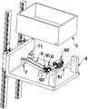
fig. 1 is a schematic structural view of the present invention;
FIG. 2 is a schematic side view of the present invention;
fig. 3 is a schematic view of the structure of the present invention;
FIG. 4 is an exploded view of the present invention;
in the figure: 1. an electric slide rail; 2. a carriage; 3. a connecting plate; 4. a mounting frame; 41. fixing the rod; 5. a material conveying box; 6. a fixed mount; 7. a connecting frame; 71. a clamping block; 8. a support frame; 9. a drive assembly; 91. a driven gear; 92. a motor; 93. the gears are driven.
Detailed Description
The technical solutions in the embodiments of the present invention will be clearly and completely described below with reference to the drawings in the embodiments of the present invention, and it is obvious that the described embodiments are only some embodiments of the present invention, not all embodiments; based on the embodiments in the present invention, all other embodiments obtained by a person skilled in the art without creative work belong to the protection scope of the present invention.
In the idle place of the device, all the electric devices and the drivers matched with the electric devices are arranged, and all the driving parts, which refer to the power element, the electric devices and the adaptive power supply, are connected through the conducting wires by the person skilled in the art, and specific connecting means refer to the following expressions that the electric connection is completed among the electric devices in sequence, and the detailed connecting means are well known in the art.
The efficient robot transfer device provided by the present embodiment, as shown in fig. 1 and fig. 3, comprises a vertical electric slide rail 1, a horizontal connecting plate 3 is clamped and slidably connected on the electric slide rail 1, a mounting frame 4 with an upward opening is fixed on the top end of the connecting plate 3, a material transporting box 5 with an initial position in the horizontal direction and an opening on the top end is hinged on the opening of the mounting frame 4, a connecting frame 7 which is positioned between the mounting frame 4 and the electric slide rail 1 and is parallel to the mounting frame 4 is clamped and slidably connected on the bottom end of the material transporting box 5, a fixing frame 6 which is positioned between the mounting frame 4 and the connecting frame 7 and is parallel to the mounting frame 4 is installed on the top end of the connecting plate 3, a connecting rod which is relatively perpendicular to the sliding direction of the connecting frame 7 is rotatably connected on both the fixing frame 6 and the connecting rod on the connecting frame 8, and the one end of keeping away from mount 6 at support frame 8 is articulated with the connecting rod on link 7, and, be provided with on connecting plate 3 and be used for driving connecting rod pivoted drive assembly 9 on mount 6, through such setting, under drive assembly 9's effect, can drive connecting rod and support frame 8 on mount 6 and rotate, support frame 8 rotates and can give link 7 an ascending power and one to the gliding power of direction of mounting bracket 4, like this, alright rotate with driving fortune workbin 5 along the position articulated with mounting bracket 4, thereby empty the material on it.
The specific operation of the driving assembly 9 is as shown in fig. 4, the driving assembly 9 includes a driven gear 91 fixedly sleeved on the outer periphery of the connecting rod on the fixing frame 6, in addition, a motor 92 is installed on the connecting plate 3, a driving gear 93 meshed with the driven gear 91 is connected on the output shaft of the motor 92 through a coupling, when the motor 92 rotates, the driving gear 93 and the driven gear 91 can rotate together, so as to drive the connecting rod on the fixing frame 6 and the supporting frame 8 to rotate.
The reason why the connecting frame 7 can be connected to the bottom end of the material transporting box 5 in a clamping and sliding manner is shown in fig. 4, a clamping block 71 is connected to the top end of the connecting frame 7, a clamping groove (not shown in the figure due to the angle of view) which is connected to the clamping block 71 in a clamping and sliding manner is formed at the bottom end of the material transporting box 5, and in addition, as shown in fig. 4, the clamping groove is a T-shaped groove, and the clamping block 71 is a T-shaped block which is matched with the T-shaped groove.
As shown in fig. 4, a fixing rod 41 is fixedly connected to the opening of the mounting frame 4, the fixing rod 41 movably penetrates through the transport box 5, and since the fixing rod 41 movably penetrates through the transport box 5, the transport box 5 is rotated instead of the fixing rod 41.
As shown in fig. 1, a carriage 2 is slidably engaged with the electric slide rail 1, the connecting plate 3 is L-shaped, and the outer side of the carriage 2 is fixedly connected to a vertical plate of the connecting plate 3.
It is noted that, herein, relational terms such as first and second, and the like may be used solely to distinguish one entity or action from another entity or action without necessarily requiring or implying any actual such relationship or order between such entities or actions. Also, the terms "comprises," "comprising," or any other variation thereof, are intended to cover a non-exclusive inclusion, such that a process, method, article, or apparatus that comprises a list of elements does not include only those elements but may include other elements not expressly listed or inherent to such process, method, article, or apparatus.
Although embodiments of the present invention have been shown and described, it will be appreciated by those skilled in the art that changes, modifications, substitutions and alterations can be made in these embodiments without departing from the principles and spirit of the invention, the scope of which is defined in the appended claims and their equivalents.
Claims (6)
1. The utility model provides an efficient robot moves and carries device, includes vertical electric slide rail (1), a serial communication port, block sliding connection has horizontally connecting plate (3) on electric slide rail (1), the top of connecting plate (3) is fixed with mounting bracket (4), it has fortune workbin (5) to articulate on mounting bracket (4), the bottom block sliding connection of fortune workbin (5) has link (7) that are located between mounting bracket (4) and electric slide rail (1) and are parallel with mounting bracket (4), the top of connecting plate (3) is installed and is located mount (6) between mounting bracket (4) and link (7) and be parallel with mounting bracket (4), all rotate on mount (6) and link (7) and be connected with the connecting rod, be fixed with support frame (8) on the connecting rod on mount (6), support frame (8) are kept away from the one end of mount (6) and are articulated with the connecting rod on link (7) articulated connecting rod And a driving component (9) for driving the connecting rod on the fixing frame (6) to rotate is arranged on the connecting plate (3).
2. The efficient robot transfer device according to claim 1, wherein the driving assembly (9) comprises a driven gear (91) fixedly sleeved on the outer periphery of the connecting rod on the fixed frame (6), a motor (92) is mounted on the connecting plate (3), and a driving gear (93) meshed with the driven gear (91) is connected to an output shaft of the motor (92) through a coupling.
3. The efficient robot transfer device according to claim 1, wherein a clamping block (71) is connected to a top end of the connecting frame (7), and a clamping groove which is clamped with the clamping block (71) and slidably connected to a bottom end of the transport box (5) is formed.
4. The efficient robot transfer device according to claim 3, wherein the locking groove is a T-shaped groove, and the locking block (71) is a T-shaped block adapted to the T-shaped groove.
5. The efficient robot transfer device as claimed in claim 1, wherein a fixing rod (41) is fixedly connected to the mounting frame (4), and the fixing rod (41) is movably penetrated through the transport box (5).
6. The efficient robot transfer device according to claim 1, wherein a carriage (2) is engaged and slidably connected to the electric slide rail (1), and an outer side of the carriage (2) is fixedly connected to the connection plate (3).
Priority Applications (1)
| Application Number | Priority Date | Filing Date | Title |
|---|---|---|---|
| CN202022881296.6U CN213894398U (en) | 2020-12-05 | 2020-12-05 | Efficient robot moves and carries device |
Applications Claiming Priority (1)
| Application Number | Priority Date | Filing Date | Title |
|---|---|---|---|
| CN202022881296.6U CN213894398U (en) | 2020-12-05 | 2020-12-05 | Efficient robot moves and carries device |
Publications (1)
| Publication Number | Publication Date |
|---|---|
| CN213894398U true CN213894398U (en) | 2021-08-06 |
Family
ID=77100399
Family Applications (1)
| Application Number | Title | Priority Date | Filing Date |
|---|---|---|---|
| CN202022881296.6U Active CN213894398U (en) | 2020-12-05 | 2020-12-05 | Efficient robot moves and carries device |
Country Status (1)
| Country | Link |
|---|---|
| CN (1) | CN213894398U (en) |
-
2020
- 2020-12-05 CN CN202022881296.6U patent/CN213894398U/en active Active
Similar Documents
| Publication | Publication Date | Title |
|---|---|---|
| CN106827603B (en) | A kind of wheel production steel ring automatic grabbing device | |
| CN212893681U (en) | Building engineering material lifting machine | |
| CN207346727U (en) | Elevator delivery structure | |
| CN213894398U (en) | Efficient robot moves and carries device | |
| CN209792924U (en) | Automatic welding machine loading attachment | |
| CN209493275U (en) | A kind of assembled architecture out-hung panel production transfer car(buggy) | |
| CN216189503U (en) | Cargo moving device for transportation | |
| CN215401512U (en) | Automatic feeding equipment of feeding vehicle | |
| CN209889805U (en) | Conveying device capable of rotating horizontally by 180 degrees | |
| CN209242105U (en) | A kind of conveying device of automobile roof liner automatic assembly line | |
| CN213265661U (en) | Rotatable chain hoisting device | |
| CN212954097U (en) | Backflow lifting mechanism of assembly line automation equipment | |
| CN209889653U (en) | Double-distance conveying device | |
| CN111687319A (en) | Bidirectional push-pull stacking mechanism for quick-change die warehouse | |
| CN109637747B (en) | Special-shaped wire coating machine | |
| CN207372581U (en) | A kind of charging tray material fetching mechanism of fuel pump automatic assembly line | |
| CN205838124U (en) | Multireel plate feeding and automatic rapid translating equipment simultaneously | |
| CN221319098U (en) | Assembly line with carrier elevating gear | |
| CN216444947U (en) | Engineering machine tool electrical equipment detects platform | |
| CN215471946U (en) | Sideslip car is used in intelligent production of ultralow energy consumption house assembly wallboard | |
| CN221337229U (en) | Automatic clamping welding fixture | |
| CN212769559U (en) | Raw materials loading attachment is used in modified starch production | |
| CN214058882U (en) | Automatic feeding device of machining center | |
| CN216038210U (en) | Grab crane for recycling waste batteries | |
| CN220879634U (en) | PCB screening and buffering device |
Legal Events
| Date | Code | Title | Description |
|---|---|---|---|
| GR01 | Patent grant | ||
| GR01 | Patent grant |