CN213848063U - Landscape atomizer - Google Patents
Landscape atomizer Download PDFInfo
- Publication number
- CN213848063U CN213848063U CN202022645205.9U CN202022645205U CN213848063U CN 213848063 U CN213848063 U CN 213848063U CN 202022645205 U CN202022645205 U CN 202022645205U CN 213848063 U CN213848063 U CN 213848063U
- Authority
- CN
- China
- Prior art keywords
- water
- pipe
- spray
- worm
- water spraying
- Prior art date
- Legal status (The legal status is an assumption and is not a legal conclusion. Google has not performed a legal analysis and makes no representation as to the accuracy of the status listed.)
- Expired - Fee Related
Links
Images


Landscapes
- Special Spraying Apparatus (AREA)
Abstract
The utility model discloses a landscape atomizer, including the spray tank, one side lateral wall fixedly connected with water pump of spray tank, and the input of water pump is through absorbing water pipe and spray tank intercommunication, the output intercommunication of water pump has the drain pipe, and sets up in the drain pipe extends to the spray tank, it is connected with the spray pipe to rotate on the spray tank, the end and the drain pipe intercommunication of intaking of spray pipe, and the play water end intercommunication of spray pipe has the atomising head, it is connected with the worm to rotate in the spray tank. The utility model relates to a landscape technical field, through setting up actuating mechanism, the staff of being convenient for controls the worm in one side of spray box and rotates, under the transmission of worm wheel, can make the worm drive the atomising head and rotate, makes things convenient for the staff to regulate and control the angle of atomising head, has avoided removing the labour loss that whole device carried out regulation and control to the angle of atomising head.
Description
Technical Field
The utility model belongs to the technical field of the landscape, especially, relate to a landscape atomizer.
Background
The basic components of landscape architecture can be divided into two main categories: one is soft things such as trees, water, wind, light rain, sunlight, sky; the other is hard things such as paving, walls, railings and landscape construction, and the soft things are called soft landscape and are usually natural; what is hard, called a hard landscape, is generally artificial.
At present, in order to guarantee the better growth of vegetation in the gardens, the staff can promote the sprinkler box cooperation atomising head to the vegetation in the gardens water spray usually, the atomising head on the sprinkler box generally is fixed design, when needing to regulate and control the angle of atomising head, generally can only remove whole sprinkler box, however, in order to increase the duration of the device, the sprinkler box volume is generally designed great, including the clear water of storage in the sprinkler box, make whole device comparatively heavy, when removing the angle of whole device regulation and control atomising head at every turn, all can be very big consume the manpower.
For this reason, we propose a landscape spraying apparatus to solve the above problems.
SUMMERY OF THE UTILITY MODEL
The utility model aims at solving the problem and providing a landscape spraying device.
In order to achieve the above purpose, the utility model adopts the following technical scheme:
the utility model provides a landscape atomizer, includes the spray box, one side lateral wall fixedly connected with water pump of spray box, and the input of water pump is through absorbing water pipe and spray box intercommunication, the output intercommunication of water pump has the drain pipe, and sets up in the drain pipe extends to the spray box, it is connected with the spray pipe to rotate on the spray box, the end and the drain pipe intercommunication of intaking of spray pipe, and the delivery end intercommunication of spray pipe has the atomising head, it is connected with the worm to rotate in the spray box, the worm wheel has been cup jointed on the spray pipe, and worm wheel mesh mutually, be provided with on the spray box with worm matched with actuating mechanism, be provided with self-locking mechanism between spray pipe and the spray box.
Preferably, the driving mechanism comprises two chain wheels and a chain, a rotating shaft is rotatably connected to the side wall of one side of the water spraying box, the chain wheels are sleeved on the rotating shaft and the worm, and the chain wheels are driven by the chain.
Preferably, self-locking mechanism includes hollow pole, slide bar, fixture block and a plurality of draw-in groove, hollow pole passes through connecting block fixed connection on the spray pipe, and slide bar sliding connection in hollow pole, a plurality of reset spring of fixedly connected with between slide bar and the hollow pole, and fixture block fixed connection on the slide bar, the upper end lateral wall of water spraying box is seted up with slide bar matched with annular spout, and a plurality of draw-in grooves are seted up on the annular spout.
Preferably, a partition plate is fixedly connected in the water spray box, and the water discharge pipe penetrates through the partition plate.
Preferably, the clamping block is designed in a spherical shape, and the clamping groove is designed in a hemispherical shape.
Preferably, the water outlet pipe is communicated with the water spraying pipe through a rotary joint.
Compared with the prior art, the beneficial effects of the utility model are that:
1. through setting up actuating mechanism, the staff of being convenient for controls the worm in one side of spray box and rotates, under the transmission of worm wheel, can make the worm drive the atomising head and rotate, makes things convenient for the staff to regulate and control the angle of atomising head, has avoided removing the labour loss that whole device carried out regulation and control to the angle of atomising head.
2. Through the annular spout that sets up, can be so that the rotation of slide bar cooperation spray pipe slides in the annular spout, guarantee spray pipe pivoted stability, the cooperation of the reset spring and the fixture block that set up in addition can drive the atomising head and rotate to suitable position when the spray pipe for the fixture block docks with the draw-in groove that corresponds, realizes the auto-lock, has avoided the loaded down with trivial details of artifical locking.
Drawings
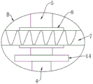
Fig. 1 is a schematic view of a front perspective structure of a garden landscape spraying device provided by the utility model;
FIG. 2 is an enlarged schematic view of the structure at A in FIG. 1;
fig. 3 is an enlarged schematic view of a portion B in fig. 1.
In the figure: the device comprises a water spraying box 1, a water pump 2, a water suction pipe 3, a water discharge pipe 4, a water spraying pipe 5, a spray head 6, a worm 7, a worm wheel 8, a driving mechanism 9, a chain wheel 91, a chain 92, a self-locking mechanism 10, a hollow rod 101, a sliding rod 102, a clamping block 103, a clamping groove 104, a rotating shaft 11, an annular sliding groove 12, a partition plate 13, a rotating joint 14, a rotating handle 15 and a return spring 16.
Detailed Description
The technical solutions in the embodiments of the present invention will be described clearly and completely with reference to the accompanying drawings in the embodiments of the present invention, and it is obvious that the described embodiments are only some embodiments of the present invention, not all embodiments.
Referring to fig. 1-3, a landscape atomizer, including spray box 1, one side lateral wall fixedly connected with water pump 2 of spray box 1, and the input of water pump 2 is through absorbing water pipe 3 and spray box 1 intercommunication, the model of water pump 2 is PUN-201EH, the output intercommunication of water pump 2 has drain pipe 4, and drain pipe 4 extends to and sets up in spray box 1, it is connected with spray pipe 5 to rotate on the spray box 1, the end of intaking of spray pipe 5 communicates with drain pipe 4, and the play water end intercommunication of spray pipe 5 has atomising head 6, communicate through rotary joint 14 between drain pipe 4 and the spray pipe 5, rotary joint 14's setting can avoid drain pipe 4 to obstruct the rotation of spray pipe 5.
There is worm 7 in the spray box 1 swivelling joint, worm wheel 8 has been cup jointed on the spray pipe 5, and worm 7 meshes with worm wheel 8 mutually, fixedly connected with baffle 13 in the spray box 1, and drain pipe 4 runs through baffle 13 and sets up, the setting of baffle 13, can avoid steam to corrode worm 7 and worm wheel 8, be provided with on the spray box 1 with worm 7 matched with actuating mechanism 9, actuating mechanism 9 includes two sprocket 91 and chain 92, one side lateral wall of spray box 1 rotates and is connected with pivot 11, and all cup jointed sprocket 91 on pivot 11 and the worm 7, through the transmission of chain 92 between two sprocket 91, through the cooperation of two sprocket 91 that set up and chain 92, the person of facilitating the use controls worm 7 at the downside of spray box 1 and rotates.
A self-locking mechanism 10 is arranged between the spray pipe 5 and the spray box 1, the self-locking mechanism 10 comprises a hollow rod 101, a slide rod 102, a clamping block 103 and a plurality of clamping grooves 104, the hollow rod 101 is fixedly connected to the spray pipe 5 through a connecting block, the slide rod 102 is slidably connected to the hollow rod 101, a plurality of reset springs 16 are fixedly connected between the slide rod 102 and the hollow rod 101, the clamping block 103 is fixedly connected to the slide rod 102, an annular sliding groove 12 matched with the slide rod 102 is formed in the side wall of the upper end of the spray box 1, the clamping grooves 104 are formed in the annular sliding groove 12, the rotational stability of the spray pipe 5 can be ensured through the matching of the slide rod 102 and the annular sliding groove 12, the reset springs 16 and the clamping block 103 which are additionally arranged can be matched with the clamping grooves 104, so that the spray head 6 can be self-locked in real time, the trouble of manual locking is avoided, the clamping block 103 is designed in a spherical shape, and the clamping grooves 104 are designed in a hemispherical shape, the structural design of the clamping block 103 and the clamping groove 104 can avoid the clamping of the two.
It is right now that the operation principle of the utility model is as follows:
in the using process of the device, firstly, the water pump 2 is started, the water pump 2 can suck water in the water spraying tank 1 through the water suction pipe 3, then the water is conveyed to the water spraying pipe 5 through the water discharge pipe 4 and is sprayed on vegetation through the spraying head 6, when the spraying angle of the spraying head 6 needs to be regulated and controlled, firstly, the rotating handle 15 is rotated, the rotating handle 15 can drive the rotating shaft 11 to rotate, the worm 7 can synchronously rotate along with the rotating shaft 11 under the transmission of the two chain wheels 91, the worm 7 can drive the water spraying pipe 5 to rotate under the transmission of the worm wheel 8, the spraying head 6 can be driven to rotate by the spraying pipe 5, meanwhile, the sliding rod 102 can slide in the annular sliding groove 12, the fixture block 103 can extrude the reset spring 16, when the spraying head 6 rotates to a required position, the fixture block 103 can be butted with the corresponding clamping groove 104, meanwhile, the reset spring 16 can release energy, so that the fixture block 103 can clamp the clamping groove 104 tightly, and the self-locking of the spraying head 6 is realized, at this time, the spray head 6 can spray water to the area to be sprayed.
The above, only be the concrete implementation of the preferred embodiment of the present invention, but the protection scope of the present invention is not limited thereto, and any person skilled in the art is in the technical scope of the present invention, according to the technical solution of the present invention and the utility model, the concept of which is equivalent to replace or change, should be covered within the protection scope of the present invention.
Claims (6)
1. A garden landscape spraying device comprises a water spraying box (1) and is characterized in that a water pump (2) is fixedly connected to the side wall of one side of the water spraying box (1), the input end of the water pump (2) is communicated with the water spraying box (1) through a water suction pipe (3), the output end of the water pump (2) is communicated with a water discharge pipe (4), the water discharge pipe (4) extends into the water spraying box (1) to be arranged, the water spraying box (1) is rotatably connected with a water spraying pipe (5), the water inlet end of the water spraying pipe (5) is communicated with the water discharge pipe (4), the water outlet end of the water spraying pipe (5) is communicated with a spraying head (6), a worm (7) is rotatably connected in the water spraying box (1), a worm wheel (8) is sleeved on the water spraying pipe (5), the worm (7) is meshed with the worm wheel (8), a driving mechanism (9) matched with the worm (7) is arranged on the water spraying box (1), and a self-locking mechanism (10) is arranged between the water spraying pipe (5) and the water spraying box (1).
2. The landscape spraying device according to claim 1, wherein the driving mechanism (9) comprises two chain wheels (91) and a chain (92), a rotating shaft (11) is rotatably connected to one side wall of the water spraying tank (1), the rotating shaft (11) and the worm (7) are respectively sleeved with the chain wheels (91), and the two chain wheels (91) are driven by the chain (92).
3. The landscape spraying device according to claim 1, wherein the self-locking mechanism (10) comprises a hollow rod (101), a sliding rod (102), a clamping block (103) and a plurality of clamping grooves (104), the hollow rod (101) is fixedly connected to the spray pipe (5) through a connecting block, the sliding rod (102) is slidably connected to the hollow rod (101), a plurality of return springs (16) are fixedly connected between the sliding rod (102) and the hollow rod (101), the clamping block (103) is fixedly connected to the sliding rod (102), an annular sliding groove (12) matched with the sliding rod (102) is formed in the side wall of the upper end of the spray box (1), and the clamping grooves (104) are formed in the annular sliding groove (12).
4. A landscape spraying apparatus according to claim 1, wherein a partition plate (13) is fixedly connected to the water spraying tank (1), and the water discharging pipe (4) is disposed through the partition plate (13).
5. A landscape spray apparatus according to claim 3, wherein the fixture block (103) is of spherical design and the fixture slot (104) is of hemispherical design.
6. A landscape spray apparatus according to claim 1, characterised in that the water discharge pipe (4) is connected to the water spray pipe (5) by means of a swivel joint (14).
Priority Applications (1)
| Application Number | Priority Date | Filing Date | Title |
|---|---|---|---|
| CN202022645205.9U CN213848063U (en) | 2020-11-16 | 2020-11-16 | Landscape atomizer |
Applications Claiming Priority (1)
| Application Number | Priority Date | Filing Date | Title |
|---|---|---|---|
| CN202022645205.9U CN213848063U (en) | 2020-11-16 | 2020-11-16 | Landscape atomizer |
Publications (1)
| Publication Number | Publication Date |
|---|---|
| CN213848063U true CN213848063U (en) | 2021-08-03 |
Family
ID=77056527
Family Applications (1)
| Application Number | Title | Priority Date | Filing Date |
|---|---|---|---|
| CN202022645205.9U Expired - Fee Related CN213848063U (en) | 2020-11-16 | 2020-11-16 | Landscape atomizer |
Country Status (1)
| Country | Link |
|---|---|
| CN (1) | CN213848063U (en) |
-
2020
- 2020-11-16 CN CN202022645205.9U patent/CN213848063U/en not_active Expired - Fee Related
Similar Documents
| Publication | Publication Date | Title |
|---|---|---|
| CN108031576B (en) | Multi-adaptability trunk whitewashing machine | |
| CN107278829A (en) | A kind of multi-faceted automatic agricultural irrigation watering device | |
| CN203618480U (en) | Machine for spraying white liquid for tree trunk | |
| CN212368075U (en) | Water-saving and water-spraying control device for landscaping | |
| CN213848063U (en) | Landscape atomizer | |
| CN212753612U (en) | Multi-functional irrigation equipment that suitable tendril medicinal material grows | |
| CN217657258U (en) | Ecological green wall of planting of view | |
| CN110710447A (en) | Irrigation equipment for garden planting | |
| CN114467715B (en) | Automatic irrigation equipment for farming | |
| CN115581193A (en) | Landscaping intelligent water-saving device and use method thereof | |
| CN215736238U (en) | Water-saving irrigation equipment for landscape landscaping isolation belt | |
| CN216135073U (en) | Afforestation construction is with spouting medicine device | |
| CN207913977U (en) | A kind of flexible trunk whitewashing machine | |
| CN213349407U (en) | Municipal works trunk whitewash equipment | |
| CN207839220U (en) | A kind of Water-saving spray device for garden landscape | |
| CN212306398U (en) | Watering device for afforestation engineering | |
| CN218869206U (en) | A spout medicine device for landscape construction | |
| CN112568099A (en) | Green, energy-saving and environment-friendly irrigation equipment for landscape | |
| CN212344832U (en) | Agricultural production uses high-efficient irrigation equipment | |
| CN220211188U (en) | Medicinal material planting canopy convenient to build | |
| CN108887030A (en) | A kind of outdoor greenhouse convenient for flower planting | |
| CN220733414U (en) | Landscape greening garden maintenance construction equipment | |
| CN215582988U (en) | Medicine device is spouted in gardens | |
| CN218789628U (en) | Irrigation equipment that landscape garden used | |
| CN216452851U (en) | Special swing regulation and control spraying plant protection machine for medlar hedgerow frame |
Legal Events
| Date | Code | Title | Description |
|---|---|---|---|
| GR01 | Patent grant | ||
| GR01 | Patent grant | ||
| CF01 | Termination of patent right due to non-payment of annual fee | ||
| CF01 | Termination of patent right due to non-payment of annual fee |
Granted publication date: 20210803 Termination date: 20211116 |