CN213796947U - Full-automatic bamboo strip loading attachment - Google Patents
Full-automatic bamboo strip loading attachment Download PDFInfo
- Publication number
- CN213796947U CN213796947U CN202022222956.XU CN202022222956U CN213796947U CN 213796947 U CN213796947 U CN 213796947U CN 202022222956 U CN202022222956 U CN 202022222956U CN 213796947 U CN213796947 U CN 213796947U
- Authority
- CN
- China
- Prior art keywords
- bamboo
- sliding seat
- feeding
- full
- clamping
- Prior art date
- Legal status (The legal status is an assumption and is not a legal conclusion. Google has not performed a legal analysis and makes no representation as to the accuracy of the status listed.)
- Expired - Fee Related
Links
- 235000017166 Bambusa arundinacea Nutrition 0.000 title claims abstract description 117
- 235000017491 Bambusa tulda Nutrition 0.000 title claims abstract description 117
- 241001330002 Bambuseae Species 0.000 title claims abstract description 117
- 235000015334 Phyllostachys viridis Nutrition 0.000 title claims abstract description 117
- 239000011425 bamboo Substances 0.000 title claims abstract description 117
- 239000000463 material Substances 0.000 claims abstract description 44
- 238000012544 monitoring process Methods 0.000 claims description 13
- 238000012546 transfer Methods 0.000 claims description 13
- 230000007306 turnover Effects 0.000 claims description 9
- 238000000034 method Methods 0.000 abstract description 5
- 230000000007 visual effect Effects 0.000 description 6
- 238000005520 cutting process Methods 0.000 description 3
- 238000004519 manufacturing process Methods 0.000 description 2
- 238000003801 milling Methods 0.000 description 2
- 238000012545 processing Methods 0.000 description 2
- 238000010521 absorption reaction Methods 0.000 description 1
- 238000004026 adhesive bonding Methods 0.000 description 1
- 238000013459 approach Methods 0.000 description 1
- 238000013461 design Methods 0.000 description 1
- 238000010586 diagram Methods 0.000 description 1
- 239000002648 laminated material Substances 0.000 description 1
- 239000003973 paint Substances 0.000 description 1
- 238000003825 pressing Methods 0.000 description 1
- XLYOFNOQVPJJNP-UHFFFAOYSA-N water Substances O XLYOFNOQVPJJNP-UHFFFAOYSA-N 0.000 description 1
Images


Landscapes
- Specific Conveyance Elements (AREA)
Abstract
The utility model relates to a full-automatic bamboo splint feeding device, which comprises a feeding mechanism, a material grabbing mechanism and a drawing mechanism; the feeding mechanism comprises a feeding frame for stacking bamboo strips; the material grabbing mechanism comprises grabbing parts used for clamping the left side and the right side of the bamboo strip, a lifting assembly driving the grabbing parts to vertically displace and a material grabbing seat erected above the feeding frame and used for fixing the lifting assembly; the drawing mechanism comprises a sliding seat, a clamping part A arranged on the sliding seat and a drawing driving component for driving the sliding seat to transversely move between the material grabbing mechanism and the inlet side of the slicing machine; the middle part of the sliding seat is provided with a conveying hole for the front end of the bamboo strip to pass through, and the clamping part A is arranged at the conveying hole. An object of the utility model is to provide a full-automatic bamboo strip loading attachment of high efficiency, intelligence. The utility model has the advantages that: the utility model comprises a feeding mechanism, a material grabbing mechanism and a drawing mechanism; the material grabbing mechanism can automatically grab the bamboo strips in the feeding mechanism and accurately feed the bamboo strips into the slitting machine through the drawing mechanism, manual participation is not needed in the feeding process, and the degree of automation is high.
Description
Technical Field
The utility model relates to a bamboo processing equipment, especially a full-automatic bamboo strip loading attachment.
Background
The bamboo board is a laminated material formed by gluing and pressing bamboo strips, has excellent physical and mechanical properties, and has the advantages of small coefficient of water absorption expansion, high strength, good stability and good toughness.
The traditional bamboo board is made by cutting bamboo into sections, removing internal and external knots, splitting into pieces, then milling one bamboo strip into bamboo blanks with the same thickness of the front end and the rear end, and finally sticking and splicing a plurality of bamboo blanks into the bamboo board.
The milling operation of the bamboo strips is completed by a planing machine. At present, the feeding of the slicing machine is still manually completed, workers need to rapidly and continuously put bamboo strips into the feeding side of the slicing machine in the production process, the feeding needs to ensure that the upper surface and the lower surface of the bamboo strips are uniform every time, namely the front surface and the back surface of the bamboo strips need to be adjusted while the feeding is carried out, the processing speed of the slicing machine is high and can reach the order of magnitude of 0.5 second, the manual feeding is adopted, the labor intensity is high, and the production efficiency of the slicing machine can be limited. In addition, the adoption of manual feeding also has certain potential safety hazard.
Disclosure of Invention
An object of the utility model is to provide a full-automatic bamboo strip loading attachment of high efficiency, intelligence.
The purpose of the utility model is realized through the following technical scheme: a full-automatic bamboo splint feeding device comprises a feeding mechanism, a grabbing mechanism and a drawing mechanism; the feeding mechanism comprises a feeding frame for stacking bamboo strips; the material grabbing mechanism comprises grabbing parts used for clamping the left side and the right side of the bamboo strip, a lifting assembly driving the grabbing parts to vertically displace and a material grabbing seat erected above the feeding frame and used for fixing the lifting assembly;
the drawing mechanism comprises a sliding seat, a clamping part A arranged on the sliding seat and a drawing driving component for driving the sliding seat to transversely move between the material grabbing mechanism and the inlet side of the slicing machine; the middle part of the sliding seat is provided with a conveying hole for the front end of the bamboo strip to pass through, and the clamping part A is arranged at the conveying hole.
Compare prior art, the utility model has the advantages of:
1. the utility model comprises a feeding mechanism, a material grabbing mechanism and a drawing mechanism; the material grabbing mechanism can automatically grab the bamboo strips in the feeding mechanism and accurately feed the bamboo strips into the slitting machine through the drawing mechanism, manual participation is not needed in the feeding process, and the degree of automation is high.
2. The drawing mechanism comprises a sliding seat, a clamping part A arranged on the sliding seat and a drawing driving component; the clamping part A comprises two clamping plates A which are oppositely arranged, and the clamping plates A adopt a one-way clamping design, namely when the sliding seat moves towards the material grabbing mechanism, the end parts of the bamboo strips open the two clamping plates A; when the sliding seat moves towards the inlet side of the slicing machine, the two clamping plates A are clamped and fixed on the upper surface and the lower surface of the bamboo batten; the sliding seat can realize the unidirectional drawing of the bamboo strips in the reciprocating motion process between the material grabbing mechanism and the inlet side of the slicing machine.
3. The drawing mechanism is provided with a turnover assembly, and the turnover assembly comprises a rotating disc and a turnover driving assembly for driving the rotating disc to rotate for 180 degrees; the turnover assembly can select whether to execute turnover operation according to the feedback data of the visual monitoring mechanism, and when the turnover is needed, the motor controls the rotating disc to rotate 180 degrees.
4. A positioning mechanism is arranged between the drawing mechanism and the inlet side of the slicing machine, when the distance between the full-automatic bamboo strip feeding device and the slicing machine is far, the front section of the bamboo strip can be fixed through the positioning mechanism, and the drawing mechanism is matched for repeated reciprocating conveying, so that accurate long-distance feeding of the bamboo strip is realized.
5. The utility model discloses can adopt duplex position structure, every station all includes grabs material mechanism, pull mechanism and positioning mechanism, and in the material loading of one of them station pull, another station snatchs the bamboo strip in the feeding frame, and two stations link up in turn, can greatly improve material loading speed.
Drawings
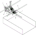
Fig. 1 is a schematic structural diagram of an embodiment of a full-automatic bamboo cane feeding device of the present invention.
Fig. 2 is a schematic perspective view of a full-automatic bamboo strip feeding device.
Fig. 3 is a front view of fig. 2.
Fig. 4 is a sectional view a-a in fig. 3.
Fig. 5 is a schematic view of the matching relationship of the material grabbing mechanism and the drawing mechanism.
Fig. 6 is a schematic view of the structure of fig. 5 from another view angle.
Description of reference numerals: the bamboo strip cutting machine comprises a feeding mechanism 1, a material grabbing mechanism 2, a grabbing part 21, a lifting component 22, a material grabbing seat 23, a drawing mechanism 3, a sliding seat 31, a conveying hole 311, a clamping part 32A, a clamping part 321A, a drawing driving component 33, a rotating disc 34, a 341 central through hole, a turning driving component 35, a bearing 36, a positioning mechanism 4, a positioning seat 41, a feeding hole 411, a clamping part 42B, a clamping part 421B, a transfer mechanism 5, a transfer mechanism 51X-axis transfer part, a transfer part 52Y-axis, a visual monitoring mechanism 6, a cutting machine 7 inlet side and bamboo strips 8.
Detailed Description
The invention is described in detail below with reference to the drawings and examples of the specification:
fig. 1-6 show schematic views of an embodiment of a full-automatic bamboo cane feeding device provided by the present invention.
A full-automatic bamboo splint feeding device comprises a feeding mechanism 1, a material grabbing mechanism 2 and a drawing mechanism 3;
the feeding mechanism 1 comprises a feeding frame for stacking bamboo strips; the bamboo strips are horizontally arranged in the feeding frame, and the front ends of the bamboo strips are propped against the front baffle plate of the feeding frame.
The front side of the feeding frame inclines downwards, and a vibration part is arranged on the feeding frame.
The material grabbing mechanism 2 comprises grabbing parts 21 used for clamping the left side and the right side of the bamboo strip, a lifting component 22 driving the grabbing parts 21 to vertically displace and a material grabbing seat 23 erected above the feeding frame and used for fixing the lifting component 22;
the grabbing part 21 is a pneumatic clamping jaw, and the clamping width of the pneumatic clamping jaw is slightly smaller than the width of the bamboo strips.
The lifting assembly 22 comprises a vertically arranged guide rail, a rack connected to the guide rail in a sliding manner, a gear meshed with the rack and a motor driving the gear to rotate, and the grabbing part 21 is fixed on the lower side of the rack.
The grabbing position of the grabbing part 21 is arranged at the front section of the bamboo batten, and a certain length is reserved between the grabbing position and the front end part of the bamboo batten and used for clamping and fixing the subsequent drawing mechanism 3.
The drawing mechanism 3 comprises a sliding seat 31, a clamping part A32 arranged on the sliding seat 31 and a drawing driving component 33 for driving the sliding seat 31 to move transversely between the material grabbing mechanism 2 and the inlet side of the slicing machine; the middle part of the sliding seat 31 is provided with a conveying hole 311 for the front end of the bamboo strip to pass through, and the clamping part A32 is arranged at the conveying hole 311.
The clamping part A32 comprises two clamping plates A321 which are oppositely arranged; the outer side edge of each clamping plate A321 is hinged on the sliding seat 31, an elastic piece is arranged on a hinged shaft of each clamping plate A321, and the inner side edge of each clamping plate A321 is driven by the elastic piece to be folded inwards;
when the sliding seat 31 moves towards the material grabbing mechanism 2, the end parts of the bamboo splints open the two clamping plates A321; when the sliding seat 31 moves towards the inlet side of the slicing machine, the two clamping plates A321 are clamped and fixed on the upper and lower surfaces of the bamboo strips.
The clamping plates a321 are disposed on the front side surface of the sliding seat 31 and are vertically and symmetrically distributed with the conveying hole 311 as the center.
A positioning mechanism 4 is arranged between the drawing mechanism 3 and the inlet side of the slicing machine;
the drawing mechanism 3 can directly feed materials to the slicing machine, when the distance between the full-automatic bamboo strip feeding device and the slicing machine is far, the front section of the bamboo strip can be fixed firstly through the positioning mechanism 4, and the drawing mechanism 3 is matched for multiple times of reciprocating conveying, so that the accurate long-distance feeding of the bamboo strip is realized.
The positioning mechanism 4 includes a positioning seat 41 and a clamping portion B42, a feeding hole 411 corresponding to the conveying hole 311 is provided on the positioning seat 41, and the clamping portion B42 is provided at the feeding hole 411.
The clamping part B42 comprises two oppositely arranged clamping plates B421; the outer side edge of each clamping plate B421 is hinged on the positioning seat 41, an elastic piece is arranged on the hinged shaft, and the inner side edge of each clamping plate B421 is driven by the elastic piece to turn inwards;
when the sliding seat 31 moves towards the positioning mechanism 4, the end parts of the bamboo strips open the two clamping plates B421; when the sliding seat 31 moves towards the material grabbing mechanism 2, the two clamping plates B421 are clamped and fixed on the upper and lower surfaces of the bamboo batten.
In the existing manual feeding process, an operator not only needs to accurately insert the bamboo strips into the inlet side of the slicing machine, but also needs to judge the front and back sides of the bamboo strips and manually turn the bamboo strips. In the above-mentioned embodiment, will solve the material loading turn-over problem, need the positive and negative orientation of unified bamboo strip in the feeding frame, the utility model discloses set up the upset subassembly in another embodiment, effectively solved the turn-over problem.
The drawing mechanism 3 further comprises a turning assembly arranged on the sliding seat 31;
the overturning assembly comprises a rotating disc 34 and an overturning driving assembly 35 for driving the rotating disc to rotate for 180 degrees;
the rotating disc 34 is connected to the sliding seat 31 through a bearing, a central through hole 341 corresponding to the conveying hole 311 is formed in the rotating disc 34, and the clamping portion a32 is formed in the central through hole 341 of the rotating disc 34.
The rotating disc 34 is a gear disc, and the overturning driving assembly 35 is a driving gear engaged with the gear disc and a motor driving the driving gear to rotate.
The full-automatic bamboo batten feeding device also comprises a transfer mechanism 5 for driving the material grabbing mechanism 2 to horizontally move in the space above the feeding frame;
the transfer mechanism 5 includes an X-axis transfer unit 51 for driving the material gripping mechanism 2 to move left and right and a Y-axis transfer unit 52 for driving the material gripping mechanism 2 to move forward and backward.
The utility model discloses can adopt the duplex position structure, every station all includes grabs material mechanism 2, pull mechanism 3 and positioning mechanism 4, in the material loading of one of them station pull, another station snatchs the bamboo strip in the feeding frame to wait for.
The full-automatic bamboo strip feeding device further comprises a vision monitoring mechanism 6, wherein the vision monitoring mechanism 6 is used for acquiring the front section image of the bamboo strips in the feeding frame, identifying and positioning the accurate positions of the bamboo strips through calculation, and judging the front and back sides of the bamboo strips.
The vision monitoring mechanism 6 positions the front end edge of the bamboo strip, recognizes the profile of the front section of the bamboo strip by taking the front end edge of the bamboo strip as an initial point, judges the position of the bamboo strip, and finally sends information to the main control end to drive the transfer mechanism 5 and the material grabbing mechanism 2 to operate; meanwhile, the visual monitoring mechanism 6 can identify the color of the front section of the bamboo strip to judge the front side and the back side of the bamboo strip, and sends information to the main control end to drive the overturning assembly to operate.
In order to improve the identification precision of the visual monitoring mechanism 6, the front end part and the rear end part of the bamboo tube can be painted (black) before the bamboo tube is cut, and a black paint surface is reserved at the end part of the cut bamboo strip, so that the visual monitoring mechanism 6 can be quickly and accurately positioned.
The working process of the full-automatic bamboo strip feeding device is as follows:
1. the bamboo strips are stacked in the feeding frame, each bamboo strip is horizontally placed, and the front end of each bamboo strip is propped against the front baffle of the feeding frame.
2. The vision monitoring mechanism 6 positions the front end edge of the bamboo strip firstly, takes the front end edge of the bamboo strip as a starting point, identifies the front section outline of the bamboo strip, and then accurately positions the position of the bamboo strip, and sends information to the main control end.
3. The transferring mechanism 5 drives the material grabbing mechanism 2 to move right above the positioned bamboo splints according to the information of the visual monitoring mechanism 6.
4. The lifting component 22 drives the grabbing part 21 to descend, when the grabbing part 21 presses the bamboo canes, the grabbing arms clamp the left side and the right side of the bamboo canes, and the lifting component 22 drives the grabbing part 21 to ascend to the horizontal height of the drawing mechanism 3.
5. The drawing driving assembly 33 drives the sliding seat 31 to move towards the material grabbing mechanism 2, the front end of the bamboo batten on the grabbing part 21 sequentially passes through the conveying hole 311 of the sliding seat 31 and the central through hole 341 of the rotating disc 34 to reach the clamping part A32, the two clamping plates A321 are stretched and then continuously move for a certain distance, after the sliding seat 31 stops, the two clamping plates A321 are clamped and fixed on the upper surface and the lower surface of the bamboo batten, and the grabbing part 21 resets and releases.
6. The turning assembly selects whether to execute turning operation according to the data identified by the vision monitoring mechanism 6, and when turning is needed, the motor controls the turning disc 34 to rotate 180 degrees.
7. The drawing driving assembly 33 drives the sliding seat 31 to move towards the positioning mechanism 4, and the two clamping plates a321 on the sliding seat 31 are clamped and fixed on the upper and lower surfaces of the bamboo batten to drive the bamboo batten to move towards the positioning mechanism 4.
8. When the bamboo batten approaches to the positioning mechanism 4, the front end of the bamboo batten firstly passes through the feeding hole 411 on the positioning seat 41, the sliding seat 31 continues to move for a certain distance after the two clamping plates B421 are spread, and after the sliding seat 31 stops, the two clamping plates B421 are clamped and fixed on the upper and lower surfaces of the bamboo batten.
9. The slide 31 is then displaced back and forth between the gripping mechanism 2 and the positioning mechanism 4 until the bamboo strands are gradually extended into the inlet side 7 of the slicer.
Claims (10)
1. The utility model provides a full-automatic bamboo strip loading attachment which characterized in that: the device comprises a feeding mechanism (1), a material grabbing mechanism (2) and a drawing mechanism (3);
the feeding mechanism (1) comprises a feeding frame for stacking bamboo strips; the material grabbing mechanism (2) comprises grabbing parts (21) used for clamping the left side and the right side of the bamboo strip, a lifting assembly (22) driving the grabbing parts (21) to vertically displace and a material grabbing seat (23) erected above the feeding frame and used for fixing the lifting assembly (22);
the drawing mechanism (3) comprises a sliding seat (31), a clamping part A (32) arranged on the sliding seat (31) and a drawing driving component (33) for driving the sliding seat (31) to transversely move between the material grabbing mechanism (2) and the inlet side of the slicing machine; the middle part of the sliding seat (31) is provided with a conveying hole (311) for the front end of the bamboo strip to pass through, and the clamping part A (32) is arranged at the conveying hole (311).
2. The full-automatic bamboo strip loading attachment of claim 1, characterized in that: the clamping part A (32) comprises two clamping plates A (321) which are arranged oppositely; the outer side edge of each clamping plate A (321) is hinged on the sliding seat (31), an elastic piece is arranged on a hinged shaft of each clamping plate A, and the inner side edge of each clamping plate A (321) is driven to be folded inwards through the elastic piece;
when the sliding seat (31) moves towards the material grabbing mechanism (2), the end parts of the bamboo splints open the two clamping plates A (321); when the sliding seat (31) moves towards the inlet side of the slicing machine, the two clamping plates A (321) are clamped and fixed on the upper surface and the lower surface of the bamboo strip.
3. The full-automatic bamboo strip loading attachment of claim 2, characterized in that: the clamping plates A (321) are arranged on the front side surface of the sliding seat (31) and are distributed in an up-and-down symmetrical mode by taking the conveying hole (311) as the center.
4. The full-automatic bamboo strip loading attachment of claim 2, characterized in that: a positioning mechanism (4) is arranged between the drawing mechanism (3) and the inlet side of the slicing machine;
positioning mechanism (4) are including positioning seat (41) and clamping part B (42), be equipped with pan feeding hole (411) that correspond with delivery hole (311) on positioning seat (41), pan feeding hole (411) department is located in clamping part B (42).
5. The full-automatic bamboo strip loading attachment of claim 4, characterized in that: the clamping part B (42) comprises two clamping plates B (421) which are arranged oppositely; the outer side edge of each clamping plate B (421) is hinged on the positioning seat (41), an elastic piece is arranged on a hinged shaft of each clamping plate B, and the inner side edge of each clamping plate B (421) is driven by the elastic piece to be folded inwards;
when the sliding seat (31) moves to the positioning mechanism (4), the end parts of the bamboo splints open the two clamping plates B (421); when the sliding seat (31) moves towards the material grabbing mechanism (2), the two clamping plates B (421) are clamped and fixed on the upper and lower surfaces of the bamboo battens.
6. The full-automatic bamboo strip loading attachment of claim 1, characterized in that: the drawing mechanism (3) also comprises a turnover component arranged on the sliding seat (31);
the overturning assembly comprises a rotating disc (34) and an overturning driving assembly (35) for driving the rotating disc (34) to rotate for 180 degrees;
the rotating disc (34) is connected to the sliding seat (31) through a bearing, a central through hole (341) corresponding to the conveying hole (311) is formed in the rotating disc (34), and the clamping portion A (32) is arranged at the central through hole (341) of the rotating disc (34).
7. The full-automatic bamboo strip loading attachment of claim 6 characterized in that: the rotary disc (34) is a gear disc, and the overturning driving assembly (35) is a driving gear meshed with the gear disc and a motor driving the driving gear to rotate.
8. The full-automatic bamboo strip loading attachment of claim 1, characterized in that: the front side of the feeding frame inclines downwards, and a vibration part is arranged on the feeding frame.
9. The full-automatic bamboo strip loading attachment of claim 1, characterized in that: the device also comprises a transfer mechanism (5) for driving the material grabbing mechanism (2) to horizontally move in the space above the feeding frame;
the transfer mechanism (5) comprises an X-axis transfer part (51) for driving the material grabbing mechanism (2) to move left and right and a Y-axis transfer part (52) for driving the material grabbing mechanism (2) to move front and back.
10. The full-automatic bamboo cane feeding device according to any one of claims 1 to 9, characterized in that: the bamboo cane feeding device is characterized by further comprising a vision monitoring mechanism (6), wherein the vision monitoring mechanism (6) is used for acquiring the front section image of the bamboo cane in the feeding frame, identifying and positioning the accurate position of the bamboo cane through calculation, and judging the front side and the back side of the bamboo cane.
Priority Applications (1)
| Application Number | Priority Date | Filing Date | Title |
|---|---|---|---|
| CN202022222956.XU CN213796947U (en) | 2020-10-01 | 2020-10-01 | Full-automatic bamboo strip loading attachment |
Applications Claiming Priority (1)
| Application Number | Priority Date | Filing Date | Title |
|---|---|---|---|
| CN202022222956.XU CN213796947U (en) | 2020-10-01 | 2020-10-01 | Full-automatic bamboo strip loading attachment |
Publications (1)
| Publication Number | Publication Date |
|---|---|
| CN213796947U true CN213796947U (en) | 2021-07-27 |
Family
ID=76956847
Family Applications (1)
| Application Number | Title | Priority Date | Filing Date |
|---|---|---|---|
| CN202022222956.XU Expired - Fee Related CN213796947U (en) | 2020-10-01 | 2020-10-01 | Full-automatic bamboo strip loading attachment |
Country Status (1)
| Country | Link |
|---|---|
| CN (1) | CN213796947U (en) |
Cited By (1)
| Publication number | Priority date | Publication date | Assignee | Title |
|---|---|---|---|---|
| CN112192666A (en) * | 2020-10-01 | 2021-01-08 | 福建省闽武机械有限公司 | Full-automatic bamboo strip loading attachment |
-
2020
- 2020-10-01 CN CN202022222956.XU patent/CN213796947U/en not_active Expired - Fee Related
Cited By (2)
| Publication number | Priority date | Publication date | Assignee | Title |
|---|---|---|---|---|
| CN112192666A (en) * | 2020-10-01 | 2021-01-08 | 福建省闽武机械有限公司 | Full-automatic bamboo strip loading attachment |
| CN112192666B (en) * | 2020-10-01 | 2024-08-16 | 福建省闽武机械有限公司 | Full-automatic bamboo strip loading attachment |
Similar Documents
| Publication | Publication Date | Title |
|---|---|---|
| CN210549494U (en) | Plate shearing and punching integrated production line | |
| CN210208503U (en) | Hydraulic riveting device for large-sized workpiece | |
| CN213796947U (en) | Full-automatic bamboo strip loading attachment | |
| CN219465100U (en) | Processing cutting equipment for hollow plastic plate | |
| CN112157756B (en) | Full-automatic bamboo strip feeding device | |
| CN215141699U (en) | Glass door and window hits rubber machine | |
| CN213976111U (en) | Special-shaped plate stacker | |
| CN213704522U (en) | Quick discharge mechanism for plastic uptake molding | |
| CN112192666A (en) | Full-automatic bamboo strip loading attachment | |
| CN210682424U (en) | Automatic rock wool board feeding device | |
| CN211238277U (en) | Film laminating mechanism for photovoltaic cell production | |
| CN213797083U (en) | Full-automatic bamboo strip feeding device | |
| CN217515462U (en) | Battery pole piece thermal laminating packaging bag making machine | |
| CN216683401U (en) | Polyethylene film blank pressing device | |
| CN214111466U (en) | Equipment of heat exchange core | |
| CN214882542U (en) | Automatic vertical and horizontal fabric slitting system | |
| CN110586713B (en) | Symmetrical bidirectional bending machine and working method thereof | |
| CN212498796U (en) | Water gap cutting equipment | |
| CN210757442U (en) | Full-automatic assembly line assembly equipment of multistation hand tool based on process flow | |
| CN110586712A (en) | Full-automatic double bending machine capable of automatically feeding and discharging and working method thereof | |
| CN115072100B (en) | Automatic assembling film sticking machine for belt buckle | |
| CN219602617U (en) | Automatic feeding and discharging device of laminating machine | |
| CN220903628U (en) | Double-claw clamping mechanism | |
| CN117484623B (en) | Automatic processing equipment of joggle mechanism at joint of round tenon standard joint | |
| CN212101203U (en) | Bamboo skin automatic feeding device |
Legal Events
| Date | Code | Title | Description |
|---|---|---|---|
| GR01 | Patent grant | ||
| GR01 | Patent grant | ||
| CF01 | Termination of patent right due to non-payment of annual fee |
Granted publication date: 20210727 |