CN213777029U - Stable three-dimensional scanning measurement auxiliary device - Google Patents
Stable three-dimensional scanning measurement auxiliary device Download PDFInfo
- Publication number
- CN213777029U CN213777029U CN202022902253.1U CN202022902253U CN213777029U CN 213777029 U CN213777029 U CN 213777029U CN 202022902253 U CN202022902253 U CN 202022902253U CN 213777029 U CN213777029 U CN 213777029U
- Authority
- CN
- China
- Prior art keywords
- sliding
- sliding block
- fixedly connected
- ring
- dimensional scanning
- Prior art date
- Legal status (The legal status is an assumption and is not a legal conclusion. Google has not performed a legal analysis and makes no representation as to the accuracy of the status listed.)
- Active
Links
Images


Abstract
The utility model belongs to the technical field of three-dimensional scanning and specifically relates to a stable three-dimensional scanning measures auxiliary device is related to, it includes the cloud platform, a plurality of bracing pieces of fixedly connected with on the cloud platform, cloud platform one end fixedly connected with solid fixed ring is kept away from to the bracing piece, gu rotate on the fixed ring and connect the rolling disc, gu be provided with drive rolling disc pivoted first driving motor on the fixed ring, the sliding chamber has been seted up on the rolling disc, the both sides of the vertical direction of sliding chamber intercommunication rolling disc, the sliding chamber sets up along rolling disc radius direction, sliding chamber sliding connection is connected with the sliding block, be provided with on the rolling disc and be used for driving the sliding block along sliding chamber slide actuating mechanism, the sliding block is close to cloud platform one side is connected with fixed camera, be provided with the upper and lower mechanism that the fixed camera of drive reciprocated between sliding block and the fixed camera. The camera fixing device has the advantages that the stability of the fixed camera after moving is improved, the possibility that the fixed camera shakes when moving to the corresponding position is reduced, and the effect of the stability of the fixed camera during shooting is improved.
Description
Technical Field
The application relates to the field of three-dimensional scanning, in particular to a stable three-dimensional scanning measurement auxiliary device.
Background
Three-dimensional scanning refers to a high and new technology integrating light, mechanical, electrical and computer technologies, and is mainly used for scanning the spatial appearance, structure and color of an object to obtain the spatial coordinates of the surface of the object. The method has the important significance that the three-dimensional information of the real object can be converted into the digital signal which can be directly processed by the computer, and a quite convenient and fast means is provided for digitalizing the real object. The three-dimensional scanning technology can realize non-contact measurement and has the advantages of high speed and high precision.
Chinese patent with publication number CN207395656U discloses a three-dimensional scanning photogrammetry auxiliary device, it includes cloud platform and a plurality of rope draw gear, rope draw gear includes the support frame, locate the rope drum and the rope traction motor that the pulley at support frame top and support frame lower extreme set up, rope traction motor is connected with the rope drum, the winding has the rope on the rope drum, rope traction motor is used for controlling the rope drum to receive and release the rope, the cloud platform includes the base, locate the rotating electrical machines on the base, the universal dish of being connected with rotating electrical machines, and the spring bracket who is connected with the universal dish, the rope is walked around the pulley is connected with base detachably, spring bracket is used for fixed camera.
In view of the above-mentioned related art, the inventor believes that the rope is easily shaken when the camera is pulled, and after the camera is adjusted to a corresponding position, the shaken camera may cause a blur in a photographed picture, and there is a possibility that the photographing is unclear.
SUMMERY OF THE UTILITY MODEL
In order to overcome the defect that a rope is easy to shake when a camera is pulled to cause blurring of pictures shot by the camera, the application provides a stable three-dimensional scanning measurement auxiliary device.
The application provides a stable three-dimensional scanning measurement auxiliary device adopts following technical scheme:
the utility model provides a stable three-dimensional scanning measurement auxiliary device, includes the cloud platform, a plurality of bracing pieces of fixedly connected with on the cloud platform, cloud platform one end fixedly connected with solid fixed ring is kept away from to the bracing piece, gu rotate on the fixed ring and connect the rolling disc, gu be provided with drive rolling disc pivoted drive motor on the fixed ring, the sliding chamber has been seted up on the rolling disc, the sliding chamber link up the both sides of the vertical direction of rolling disc, the sliding chamber sets up along rolling disc radius direction, sliding chamber sliding connection is connected with the sliding block in the sliding chamber, be provided with on the rolling disc and be used for driving the sliding block along sliding chamber sliding drive mechanism, the sliding block is close to cloud platform one side is connected with fixed camera, the sliding block with be provided with the upper and lower mechanism that the fixed camera of drive reciprocated between the fixed camera.
Through adopting above-mentioned technical scheme, set up solid fixed ring on the cloud platform, and rotate on solid fixed ring and connect the rolling disc, set up the slip chamber on the rolling disc, slip intracavity sliding connection sliding block, the sliding block passes through the upper and lower mechanism and connects fixed camera, through the slip of sliding block in the slip intracavity and the rotation of rolling disc on solid fixed ring, can realize that fixed camera all-round in the plane moves steadily, it reciprocates to drive fixed camera through the upper and lower mechanism, the realization is with all-round steady removal of fixed camera in the space of cloud platform top, improve the stability of fixed camera after the removal, reduce the fixed camera and remove the possibility that relevant position rocked, stability when improving fixed camera and shoot.
Optionally, the driving mechanism comprises two fixed plates fixedly connected to one side of the rotating disc, which deviates from the pan-tilt, a screw rod rotatably connected between the two fixed plates, a second driving motor used for driving the screw rod to rotate, and a driving block fixedly connected to one side of the sliding block, which is far away from the pan-tilt, wherein the screw rod penetrates through the driving block and is in threaded connection with the driving block.
By adopting the technical scheme, the driving block is driven to move by driving the screw rod between the fixing plates to rotate, so that the sliding block is driven to move, the sliding block is stable and adjustable to move, the self-locking function after the screw rod is driven improves the stability of the driving block when the driving block is displaced to a required position, and the possibility that the sliding block continues to slide along the length direction of the sliding cavity after reaching a specified position is reduced.
Optionally, the up-down mechanism comprises a plurality of connecting rods fixedly connected to one side, close to the holder, of the sliding block, a connecting plate fixedly connected to one end, far away from the sliding block, of the connecting rod, a cylinder fixedly connected to the connecting plate, and a pushing plate fixedly connected to a pushing rod of the cylinder, wherein one end, far away from the cylinder, of the pushing plate is connected with the fixed camera.
Through adopting above-mentioned technical scheme, fixed connection cylinder on the connecting plate drives fixed camera through the push rod of cylinder and removes, makes things convenient for fixed camera to remove along vertical direction, and the cylinder makes things convenient for the position control of fixed camera vertical direction to improve the stability that fixed camera was adjusted simultaneously.
Optionally, one side of the pushing plate, which is close to the connecting plate, is fixedly connected with a plurality of limiting rods, and the limiting rods penetrate through the connecting plate in a sliding manner.
Through adopting above-mentioned technical scheme, fixed connection gag lever post on the push plate wears to establish the connecting plate through the gag lever post slip and comes the push plate spacing, reduces the push plate and follows the possibility that the horizontal direction rocked when displacement from top to bottom, stability when improving the push plate displacement from top to bottom to stability when improving fixed camera and shooing.
Optionally, one side of the rotating disc, which is close to the holder, is fixedly connected with an annular rack, the annular rack is located on one side of the rotating disc, which is far away from the circle center, the driving rod of the first driving motor penetrates through the side wall of the fixing ring and is fixedly connected with a gear, and the gear is meshed with the annular rack.
Through adopting above-mentioned technical scheme, be close to cloud platform one side fixed connection annular rack at the rolling disc, drive annular rack through first driving motor and rotate to the drive rolling disc rotates, has made things convenient for the rotation of rolling disc, only needs the rotation of control motor, just can adjust rolling disc pivoted angle, thereby drives fixed camera and rotates, makes things convenient for the regulation of fixed camera position, improves the stability when fixed camera removes simultaneously.
Optionally, fixedly connected with erects the ring on the rolling disc, it is located solid fixed ring and keeps away from cloud platform one side to erect the ring, erect the ring and be close to solid fixed ring one side and gu fixed ring keep away from cloud platform one side and rotate and contradict.
Through adopting above-mentioned technical scheme, fixed connection erects the ring on the rolling disc, establishes the rolling disc frame on solid fixed ring through erectting the ring, has made things convenient for the installation of rolling disc to spacing on erectting the ring with the rolling disc through gravity, stability when improving the rolling disc and rotating reduces the possibility of rolling disc displacement from top to bottom.
Optionally, the limiting grooves are formed in two sides of the sliding cavity in the length direction, limiting blocks are arranged on two sides of the sliding block, and the limiting blocks are connected in the limiting grooves in a sliding mode.
Through adopting above-mentioned technical scheme, set up the spacing groove in sliding chamber length direction's both sides, set up the stopper in the sliding block both sides, through the slip of stopper in the spacing inslot, reduce the possibility that the sliding block rocked when sliding, stability when improving the camera and remove.
Optionally, a lubricating layer is coated on one side, close to the fixing ring, of the erection ring.
Through adopting above-mentioned technical scheme, erect the ring and be close to solid fixed ring one side and scribble and establish the lubricant film, frictional force when can reducing to erect ring and solid fixed ring relative rotation improves the efficiency when a driving motor drive rolling disc rotates to the regulation of convenient fixed camera position.
In summary, the present application includes at least one of the following beneficial technical effects:
1. the fixed camera can move stably in all directions in a plane through the sliding of the sliding block in the sliding cavity and the rotation of the rotating disc on the fixed ring, the fixed camera is driven to move up and down through the up-down mechanism, the fixed camera can move stably in all directions in the space above the holder, the stability of the fixed camera after moving is improved, the possibility that the fixed camera shakes when moving to a corresponding position is reduced, and the stability of the fixed camera during shooting is improved;
2. the driving block is driven to move by driving the screw rod between the fixing plates to rotate, so that the sliding block is driven to move, the sliding block is enabled to move stably and adjustably, the self-locking function after the screw rod is driven improves the stability of the driving block when the driving block moves to a required position, and the possibility that the sliding block continues to slide along the length direction of the sliding cavity after reaching a specified position is reduced;
3. fixed connection gag lever post on the push plate slides through establishing the connecting plate through the gag lever post and comes to push plate spacing, reduces the push plate and follows the possibility that the horizontal direction rocked when displacement from top to bottom, stability when improving the push plate displacement from top to bottom to stability when improving fixed camera and shooing.
Drawings
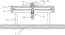
Fig. 1 is a schematic structural diagram of a stable three-dimensional scanning measurement auxiliary device in an embodiment of the present application.
Fig. 2 is a schematic structural diagram of a rotating disk of a stable three-dimensional scanning measurement auxiliary device in an embodiment of the present application.
FIG. 3 is a cross-sectional view of the stabilized three-dimensional scanning measurement aid of the embodiment of the present application along the length of the sliding chamber.
Fig. 4 is a cross-sectional view of the stabilized three-dimensional scanning measurement auxiliary device in the width direction of the sliding chamber in the embodiment of the present application.
Fig. 5 is a schematic structural diagram of an up-down mechanism of the stable three-dimensional scanning measurement auxiliary device in the embodiment of the present application.
Description of reference numerals: 1. a holder; 2. a support bar; 3. a fixing ring; 31. a first drive motor; 32. a gear; 4. rotating the disc; 41. an annular rack; 42. erecting a ring; 5. a sliding cavity; 51. a limiting groove; 6. a slider; 61. a limiting block; 7. a drive mechanism; 71. a fixing plate; 72. a screw rod; 73. a second drive motor; 74. a drive block; 8. an up-down mechanism; 81. a connecting rod; 82. a connecting plate; 83. a cylinder; 84. a push plate; 9. a limiting rod; 10. the camera is fixed.
Detailed Description
The present application is described in further detail below with reference to figures 1-5.
The embodiment of the application discloses stable three-dimensional scanning measurement auxiliary device. Referring to fig. 1, the stable three-dimensional scanning measurement auxiliary device includes a cradle head 1, the cradle head 1 is arranged in a rectangular shape, and the cradle head 1 is used for placing an object to be photographed. The pan/tilt head 1 is connected with a fixed camera 10 which can move stably in all directions.
Referring to fig. 1, four bracing pieces 2 of fixedly connected with are gone up to cloud platform 1, and four bracing pieces 2 are located four corners of 1 mesa of cloud platform, and 1 one end fixedly connected with solid fixed ring 3 of cloud platform is kept away from to four bracing pieces 2, and solid fixed ring 3 is the ring form, and solid fixed ring 3 is last to rotate and is connected with rolling disc 4, and 4 quotations of rolling disc are circular setting.
Referring to fig. 1 and 2, an erection ring 42 is fixedly connected to a side wall of the rotary disk 4 away from the center, the erection ring 42 is located at one end of the side wall of the rotary disk 4 away from the pan/tilt head 1, and the erection ring 42 and the rotary disk 4 are integrally formed. Erect ring 42 and be close to 1 one side of cloud platform and solid fixed ring 3 and keep away from 1 one side of cloud platform and rotate and contradict, erect rotating disk 4 on solid fixed ring 3, erect ring 42 and be close to solid fixed ring 3 one side and scribble and be equipped with the lubricant film, the lubricant film is the polytetrafluoroethylene layer in this embodiment, and the polytetrafluoroethylene layer can reduce the frictional force when erectting ring 42 and solid fixed ring 3 relative rotation, conveniently erects ring 42 and solid fixed ring 3's relative rotation.
Referring to fig. 2 and 3, an annular rack 41 is fixedly connected to one side of the rotating disc 4 close to the pan/tilt head 1, the annular rack 41 is in a ring shape, and the annular rack 41 is located on one side of the rotating disc 4 away from the center of the disc surface. The fixed ring 3 lateral wall is provided with first driving motor 31, and the motor casing fixed connection of first driving motor 31 is at the fixed ring 3 lateral wall of keeping away from fixed ring 3 center one side, and fixed ring 3 lateral wall and fixedly connected with gear 32 are passed to first driving motor 31's actuating lever, and gear 32 and annular rack 41 mesh make the annular rack 41 with gear 32 mesh rotate through the drive of first driving motor 31 to drive rolling disc 4 rotates.
Referring to fig. 3 and 4, sliding cavity 5 has been seted up on rolling disc 4, sliding cavity 5 sets up along the radius direction of 4 quotations of rolling disc, sliding cavity 5 link up rolling disc 4 along vertical direction, sliding connection has sliding block 6 in sliding cavity 5, sliding block 6 is the cuboid setting, sliding cavity 5 has seted up spacing groove 51 along length direction's both sides wall, sliding block 6 lateral wall fixedly connected with stopper 61, sliding block 6 and stopper 61 integrated into one piece, stopper 61 sliding connection is in spacing groove 51. Through stopper 61 sliding connection in spacing groove 51, it is spacing with sliding block 6 along vertical direction, improve sliding block 6 gliding stability in sliding chamber 5.
Referring to fig. 3 and 4, a driving mechanism 7 for driving the sliding block 6 to slide in the sliding cavity 5 is disposed on the rotating disc 4, and the driving mechanism 7 includes two fixing plates 71 fixedly connected to a side of the rotating disc 4 away from the pan/tilt head 1, a screw 72 rotatably connected between the two fixing plates 71, a second driving motor 73 located on a side of the rotating disc 4 away from the pan/tilt head 1 for driving the screw 72 to rotate, and a driving block 74 fixedly connected to a side of the sliding block 6 away from the pan/tilt head 1.
Referring to fig. 3, the screw rod 72 is located right above the sliding cavity 5 and is parallel to the length direction of the sliding cavity 5, the screw rod 72 penetrates through the driving block 74 and is in threaded connection with the driving block 74, and the driving rod of the second driving motor 73 is fixedly connected with the screw rod 72. The screw 72 is driven to rotate by the second driving motor 73, so that the driving block 74 is driven to move along the axial direction of the screw 72, and the sliding block 6 is driven to slide in the sliding cavity 5.
Referring to fig. 4, the side of the sliding block 6 away from the driving block 74 is connected to the fixed camera 10, and an up-down mechanism 8 for driving the fixed camera 10 to move up and down is connected between the sliding block 6 and the fixed camera 10.
Referring to fig. 5, the up-down mechanism 8 includes a plurality of connecting rods 81 fixedly connected to the side of the sliding block 6 away from the driving block 74, a connecting plate 82 fixedly connected to the end of the connecting rod 81 away from the sliding block 6, an air cylinder 83 connected to the connecting plate 82, and a push plate 84 fixedly connected to the push rod of the air cylinder 83.
Referring to fig. 5, the connecting rods 81 are cylindrically disposed, and the number of the connecting rods 81 is two in this embodiment. The surface of the connecting plate 82 is square. The cylinder body of the cylinder 83 is located on one side of the connecting plate 82 close to the sliding block 6 and is fixedly connected with the connecting rod 81, and the push rod of the cylinder 83 penetrates through the connecting plate 82 in a sliding mode. The pushing plate 84 is square in surface, and one side of the pushing plate 84 away from the cylinder 83 is fixedly connected with the fixed camera 10.
Referring to fig. 5, one side of the push plate 84, which is close to the connecting plate 82, is fixedly connected with a plurality of limiting rods 9, in this embodiment, the number of the limiting rods 9 is two, the limiting rods 9 penetrate through the connecting plate 82 in a sliding manner, when the push rod of the cylinder 83 pushes the push plate 84 to move, the horizontal direction of the push plate 84 is limited by the sliding of the limiting rods 9 in the connecting plate 82, and the stability of the vertical mechanism 8 when driving the fixed camera 10 to move up and down is improved.
The implementation principle of the stable three-dimensional scanning measurement auxiliary device in the embodiment of the application is as follows: the holder 1 is provided with a fixed ring 3, the fixed ring 3 is rotationally connected with a rotating disc 4 driven by a first driving motor 31, the rotating disc 4 is rotated to drive the fixed camera 10 to rotate by an angle, the rotating disc 4 is provided with a sliding cavity 5, a sliding block 6 is slidably connected in the sliding cavity 5, a driving mechanism 7 drives the sliding block 6 to slide in the sliding cavity 5 to drive the fixed camera 10 to stably slide along the direction of the sliding cavity 5, through set up the upper and lower mechanism 8 that has cylinder 83 between fixed camera 10 and sliding block 6, make things convenient for fixed camera 10 to move along vertical direction stability, realize moving fixed camera 10 all-round steadily in the space of cloud platform 1 top, improve the stability of fixed camera 10 after the removal, reduce fixed camera 10 and remove the possibility that relevant position rocked, stability when improving fixed camera 10 and shoot.
The above embodiments are preferred embodiments of the present application, and the protection scope of the present application is not limited by the above embodiments, so: all equivalent changes made according to the structure, shape and principle of the present application shall be covered by the protection scope of the present application.
Claims (8)
1. The utility model provides a stable three-dimensional scanning measurement auxiliary device, includes cloud platform (1), its characterized in that: the cradle head is characterized in that a plurality of support rods (2) are fixedly connected to the cradle head (1), one end of each support rod (2) far away from the cradle head (1) is fixedly connected with a fixing ring (3), the fixing ring (3) is rotatably connected with a rotating disc (4), a first driving motor (31) for driving the rotating disc (4) to rotate is arranged on the fixing ring (3), a sliding cavity (5) is formed in the rotating disc (4), the sliding cavity (5) penetrates through two sides of the rotating disc (4) in the vertical direction, the sliding cavity (5) is arranged along the radius direction of the rotating disc (4), a sliding block (6) is connected in the sliding cavity (5) in a sliding connection mode, a sliding driving mechanism (7) for driving the sliding block (6) to slide along the sliding cavity (5) is arranged on the rotating disc (4), and the sliding block (6) is close to one side of the cradle head (1) and is connected with a fixed camera (10), an up-down mechanism (8) for driving the fixed camera (10) to move up and down is arranged between the sliding block (6) and the fixed camera (10).
2. The stabilized three-dimensional scanning measurement assistance device according to claim 1, characterized in that: actuating mechanism (7) include two fixed connection at fixed plate (71) that carousel (4) deviates from cloud platform (1) one side, rotate lead screw (72) of connection between two fixed plate (71), be used for driving lead screw (72) pivoted second driving motor (73), fixed connection keep away from cloud platform (1) one side drive block (74) at sliding block (6), lead screw (72) are worn to establish drive block (74) and with drive block (74) threaded connection.
3. The stabilized three-dimensional scanning measurement assistance device according to claim 1, characterized in that: the up-down mechanism (8) comprises a plurality of connecting rods (81) fixedly connected to one side, close to the holder (1), of the sliding block (6), a connecting plate (82) far away from one end of the sliding block (6) through the connecting rods (81), a cylinder (83) fixedly connected to the connecting plate (82), and a pushing plate (84) fixedly connected to a pushing rod of the cylinder (83), wherein one end, far away from the cylinder (83), of the pushing plate (84) is connected with the fixed camera (10).
4. The stabilized three-dimensional scanning measurement assistance device according to claim 3, characterized in that: one side of the pushing plate (84) close to the connecting plate (82) is fixedly connected with a plurality of limiting rods (9), and the limiting rods (9) penetrate through the connecting plate (82) in a sliding mode.
5. The stabilized three-dimensional scanning measurement assistance device according to claim 1, characterized in that: the turntable (4) is close to the annular rack (41) fixedly connected with one side of the holder (1), the annular rack (41) is located on one side of the turntable (4) away from the circle center, the driving rod of the first driving motor (31) penetrates through the side wall of the fixing ring (3) and the fixedly connected gear (32), and the gear (32) is meshed with the annular rack (41).
6. The stabilized three-dimensional scanning measurement assistance device according to claim 1, characterized in that: fixedly connected with erects ring (42) on rolling disc (4), erect ring (42) and be located solid fixed ring (3) and keep away from cloud platform (1) one side, erect ring (42) and be close to solid fixed ring (3) one side and gu fixed ring (3) keep away from cloud platform (1) one side and rotate the conflict.
7. The stabilized three-dimensional scanning measurement assistance device according to claim 1, characterized in that: spacing groove (51) have been seted up to sliding chamber (5) length direction's both sides, sliding block (6) both sides are provided with stopper (61), stopper (61) sliding connection is in spacing groove (51).
8. The stabilized three-dimensional scanning measurement assistance device according to claim 6, characterized in that: and a lubricating layer is coated on one side of the erection ring (42) close to the fixing ring (3).
Priority Applications (1)
| Application Number | Priority Date | Filing Date | Title |
|---|---|---|---|
| CN202022902253.1U CN213777029U (en) | 2020-12-03 | 2020-12-03 | Stable three-dimensional scanning measurement auxiliary device |
Applications Claiming Priority (1)
| Application Number | Priority Date | Filing Date | Title |
|---|---|---|---|
| CN202022902253.1U CN213777029U (en) | 2020-12-03 | 2020-12-03 | Stable three-dimensional scanning measurement auxiliary device |
Publications (1)
| Publication Number | Publication Date |
|---|---|
| CN213777029U true CN213777029U (en) | 2021-07-23 |
Family
ID=76896508
Family Applications (1)
| Application Number | Title | Priority Date | Filing Date |
|---|---|---|---|
| CN202022902253.1U Active CN213777029U (en) | 2020-12-03 | 2020-12-03 | Stable three-dimensional scanning measurement auxiliary device |
Country Status (1)
| Country | Link |
|---|---|
| CN (1) | CN213777029U (en) |
Cited By (2)
| Publication number | Priority date | Publication date | Assignee | Title |
|---|---|---|---|---|
| CN113944845A (en) * | 2021-10-27 | 2022-01-18 | 深圳市瑞峰建设有限公司 | Building construction system based on BIM |
| CN115165737A (en) * | 2022-06-24 | 2022-10-11 | 群策精密金属(苏州)有限公司 | Visual detection device and detection method thereof |
-
2020
- 2020-12-03 CN CN202022902253.1U patent/CN213777029U/en active Active
Cited By (2)
| Publication number | Priority date | Publication date | Assignee | Title |
|---|---|---|---|---|
| CN113944845A (en) * | 2021-10-27 | 2022-01-18 | 深圳市瑞峰建设有限公司 | Building construction system based on BIM |
| CN115165737A (en) * | 2022-06-24 | 2022-10-11 | 群策精密金属(苏州)有限公司 | Visual detection device and detection method thereof |
Similar Documents
| Publication | Publication Date | Title |
|---|---|---|
| CN213777029U (en) | Stable three-dimensional scanning measurement auxiliary device | |
| CN109555959B (en) | High-speed aerial photography cloud platform | |
| WO2018082249A1 (en) | Multi-angle photographing support frame and system | |
| CN113163130B (en) | Shooting auxiliary equipment, image pair acquisition calibration method and electronic equipment | |
| CN211001895U (en) | Five-lens oblique camera convenient for angle adjustment and used for aerial surveying and mapping | |
| CN212009254U (en) | Three-dimensional slide rail device for camera | |
| CN101907824B (en) | Three-dimensional image-taking device | |
| CN108038901A (en) | Object space three-dimensional imaging data generation system | |
| WO2019205077A1 (en) | Image acquisition apparatus | |
| CN210005841U (en) | moving shooting device based on stop motion animation | |
| CN218954502U (en) | Video camera | |
| CN207968681U (en) | A kind of device for image of image measurer | |
| CN206413091U (en) | A kind of panoramic camera data acquisition and caliberating device | |
| CN215554220U (en) | Unmanned aerial vehicle camera installation cloud platform | |
| CN210687572U (en) | Semi-automatic doubling slide rail for mobile phone photography | |
| US11079662B2 (en) | Rotatable platform riser system | |
| CN209043315U (en) | Digital aviation panoramic measuring camera platform | |
| CN211063717U (en) | Camera equipment for film stereo shooting | |
| CN106292166A (en) | A kind of three-dimensional panorama camera | |
| CN208476244U (en) | A kind of aerial survey of unmanned aerial vehicle image motion compensation device | |
| CN208919591U (en) | A kind of acquisition camera convenient for adjusting position | |
| CN218599293U (en) | Adjusting mechanism for camera | |
| CN205720824U (en) | A kind of automatic transfer switch of optical filter switch | |
| CN105898150B (en) | The filming apparatus that 3D printer uses | |
| CN214037732U (en) | Clear image projector of formation of image |
Legal Events
| Date | Code | Title | Description |
|---|---|---|---|
| GR01 | Patent grant | ||
| GR01 | Patent grant |