CN213763073U - Cleaning equipment for metal processing - Google Patents
Cleaning equipment for metal processing Download PDFInfo
- Publication number
- CN213763073U CN213763073U CN202022253796.5U CN202022253796U CN213763073U CN 213763073 U CN213763073 U CN 213763073U CN 202022253796 U CN202022253796 U CN 202022253796U CN 213763073 U CN213763073 U CN 213763073U
- Authority
- CN
- China
- Prior art keywords
- water
- mount
- collecting box
- frame
- fixed mounting
- Prior art date
- Legal status (The legal status is an assumption and is not a legal conclusion. Google has not performed a legal analysis and makes no representation as to the accuracy of the status listed.)
- Expired - Fee Related
Links
Images


Abstract
The utility model discloses a cleaning equipment for metal processing, which comprises a supporting table, the top fixed mounting of brace table has the mount, the left side of mount and the top fixed mounting who is located the brace table have the storage water tank, the left side fixed mounting at mount top has the water pump, the inlet tube and the storage water tank intercommunication of water pump, the outlet pipe of water pump runs through to the inside intercommunication of mount has the drain pipe, the bottom intercommunication of drain pipe has the shower nozzle, the center department fixed mounting at brace table top has the processing platform. The utility model discloses a two filter screens can block the piece granule in the waste water in grades, and the waste water flow is concentrated to the inside of collecting box and is collected, can avoid causing the water waste, can carry out purification treatment once more to the waste water after collecting to utilize, practiced thrift the water resource, accord with enterprise's environmental protection theory, solved the waste water after wasing simultaneously and all directly discharged out, wasted the problem of water resource from this.
Description
Technical Field
The utility model relates to a metal processing technology field specifically is a cleaning equipment for metal processing.
Background
Raw materials conveying equipment for metal processing belongs to one kind of conveyer belt transportation, utilize the rotary motion or reciprocating motion of equipment component, or utilize the flow of medium in the pipeline to make the material carry forward, conveyer belt conveyer receives the influence of machine-building, including motor, chemical industry and metallurgical industry technological progress, thereby it is constantly perfect, become the material handling system mechanization and the indispensable component part of automation, need wash the metal parts among the metal working process, in order to guarantee processingquality, but the waste water after the washing all directly discharges away, the water resource has been wasted from this, be not conform to the environmental protection theory of enterprise.
SUMMERY OF THE UTILITY MODEL
An object of the utility model is to provide a cleaning equipment for metal processing possesses the advantage that can handle waste water collection, has solved the waste water after the washing and all directly discharges away, has wasted the problem of water resource from this.
In order to achieve the above object, the utility model provides a following technical scheme: the utility model provides a cleaning equipment for metal processing, includes a supporting bench, the top fixed mounting of brace table has the mount, the left side of mount and the top fixed mounting who is located the brace table have the storage water tank, the left side fixed mounting at mount top has the water pump, the inlet tube and the storage water tank intercommunication of water pump, the inside intercommunication that the outlet pipe of water pump runs through to the mount has the drain pipe, the bottom intercommunication of drain pipe has the shower nozzle, the center department fixed mounting at brace table top has the processing platform, the shower nozzle is located the processing platform directly over, the equal fixed mounting in both sides that the top of brace table is located the processing platform has the frame, the inside of frame is provided with the filter screen, the installation cavity has been seted up to the inside of brace table, and the inside of installation cavity has placed the collecting box, the top of collecting box and the bottom intercommunication of frame.
Preferably, the two sides of the top of the drain pipe are fixedly provided with universal shafts, and the upper ends of the universal shafts are fixedly arranged on the top of the inner cavity of the fixing frame.
Preferably, the two sides of the inner cavity of the frame are fixedly provided with positioning blocks, the filter screen is erected at the top of the positioning blocks, and the filter screen is provided with an upper layer and a lower layer.
Preferably, through holes are formed in the two sides of the top of the supporting table and are located at the bottom of the frame and communicated with the inside of the collecting box.
Preferably, the front surface of the supporting table is rotatably provided with an operating door through a hinge, and the operating door is arranged corresponding to the position of the collecting box.
Compared with the prior art, the beneficial effects of the utility model are as follows:
1. the utility model discloses a two filter screens can block the piece granule in the waste water in grades, and the waste water flow is concentrated to the inside of collecting box and is collected, can avoid causing the water waste, can carry out purification treatment once more to the waste water after collecting to utilize, practiced thrift the water resource, accord with enterprise's environmental protection theory, solved the waste water after wasing simultaneously and all directly discharged out, wasted the problem of water resource from this.
2. The utility model discloses an cardan shaft can adjust the inclination of drain pipe, can improve the cleaning efficiency to metal parts, and the filter screen directly is taken and is established at the top of locating piece simultaneously, and the convenience is taken out and is cleared up the filter screen.
Drawings
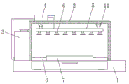
FIG. 1 is a schematic structural view of the present invention;
FIG. 2 is a sectional view of the supporting platform of the present invention;
fig. 3 is a cross-sectional view of the frame structure of the present invention.
In the figure: 1. a support table; 2. a fixed mount; 3. a water storage tank; 4. a water pump; 5. a drain pipe; 6. a spray head; 7. a processing table; 8. a frame; 9. a filter screen; 10. a collection box; 11. a cardan shaft.
Detailed Description
The technical solutions in the embodiments of the present invention will be described clearly and completely with reference to the accompanying drawings in the embodiments of the present invention, and it is obvious that the described embodiments are only some embodiments of the present invention, not all embodiments. Based on the embodiments in the present invention, all other embodiments obtained by a person skilled in the art without creative work belong to the protection scope of the present invention.
In the description herein, it is to be understood that the terms "center," "upper," "lower," "front," "rear," "left," "right," "vertical," "horizontal," "top," "bottom," "inner," "outer," and the like are used in the orientations and positional relationships indicated in the drawings to facilitate the description of the patent and to simplify the description, but do not indicate or imply that the referenced device or element must have a particular orientation, be constructed and operated in a particular orientation, and thus are not to be considered limiting of the patent. In the description of the present application, it should be noted that unless otherwise explicitly stated or limited, the terms "mounted," "connected," and "disposed" are to be construed broadly and can, for example, be fixedly connected, disposed, detachably connected, disposed, or integrally connected and disposed. The specific meaning of the above terms in this patent may be understood by those of ordinary skill in the art as appropriate.
Referring to fig. 1-3, a cleaning device for metal processing comprises a supporting table 1, through holes are formed in both sides of the top of the supporting table 1, the through holes are located at the bottom of a frame 8 and communicated with the inside of a collecting box 10, an operation door is rotatably installed on the front of the supporting table 1 through hinges and is arranged corresponding to the position of the collecting box 10, a fixed frame 2 is fixedly installed at the top of the supporting table 1, a water storage box 3 is fixedly installed on the left side of the fixed frame 2 and located at the top of the supporting table 1, a water pump 4 is fixedly installed on the left side of the top of the fixed frame 2, a water inlet pipe of the water pump 4 is communicated with the water storage box 3, a water outlet pipe of the water pump 4 is communicated with a water outlet pipe 5 penetrating through the inside of the fixed frame 2, universal shafts 11 are fixedly installed on both sides of the top, the cleaning efficiency of metal parts can be improved, meanwhile, the filter screen 9 is directly erected at the top of the positioning block, the filter screen 9 is conveniently taken out and cleaned, the bottom of the water discharge pipe 5 is communicated with the spray head 6, the center of the top of the support table 1 is fixedly provided with the processing table 7, the spray head 6 is positioned right above the processing table 7, the top of the support table 1 and two sides of the processing table 7 are both fixedly provided with the frame 8, the positioning block is fixedly arranged at two sides of an inner cavity of the frame 8, the filter screen 9 is erected at the top of the positioning block, the filter screen 9 is provided with an upper layer and a lower layer, the filter screen 9 is arranged inside the frame 8, the mounting cavity is arranged inside the support table 1, the collecting box 10 is arranged inside the mounting cavity, the top of the collecting box 10 is communicated with the bottom of the frame 8, the debris particles in the wastewater can be classified and blocked through the two filter screens 9, and the wastewater flows to the inside of the collecting box 10 to be collected in a concentrated manner, can avoid causing water waste, can carry out purification treatment once more to the waste water after collecting to utilize, practiced thrift the water resource, accord with enterprise's environmental protection theory, it all directly discharges away to have solved the waste water after the washing simultaneously, has wasted the problem of water resource from this.
All the components in the utility model are universal standard components or components known by technicians in the field, the structure and principle of the components are known by technicians in the technical manual or known by conventional experimental methods, standard parts used in the application document can be purchased from the market, the components in the application document can be customized according to the description of the specification and the accompanying drawings, the specific connection mode of each component adopts conventional means such as bolts, rivets, welding and the like mature in the prior art, machines, parts and equipment adopt conventional models in the prior art, the control mode is automatically controlled by a controller, a control circuit of the controller can be realized by simple programming of technicians in the field, the components belong to the common knowledge in the field, and the application document is mainly used for protecting mechanical devices, so the control mode and circuit connection are not explained in detail in the application document, no specific description will be made herein.
During the use, start water pump 4 and carry the inside water of storage water tank 3 to drain pipe 5 through 6 blowout of shower nozzle, spray the in-process accessible cardan shaft 11 and adjust the angle of spraying of drain pipe 5, waste water after the metal part washs flows to the inside of frame 8 together with the piece, can block the filtration in grades to big or small piece granule in the waste water through two filter screens 9, waste water flows to the inside of collecting box 10 once more afterwards and concentrates the collection, can recycle the waste water after the preliminary treatment, avoid extravagant, water economy resource.
Although embodiments of the present invention have been shown and described, it will be appreciated by those skilled in the art that changes, modifications, substitutions and alterations can be made in these embodiments without departing from the principles and spirit of the invention, the scope of which is defined in the appended claims and their equivalents.
Claims (5)
1. The utility model provides a cleaning equipment for metalworking, includes brace table (1), its characterized in that: the top of the supporting table (1) is fixedly provided with a fixing frame (2), the left side of the fixing frame (2) and the top of the supporting table (1) are fixedly provided with a water storage tank (3), the left side of the top of the fixing frame (2) is fixedly provided with a water pump (4), a water inlet pipe of the water pump (4) is communicated with the water storage tank (3), a water outlet pipe of the water pump (4) penetrates through the fixing frame (2) and is communicated with a water outlet pipe (5), the bottom of the water outlet pipe (5) is communicated with a spray head (6), the center of the top of the supporting table (1) is fixedly provided with a processing table (7), the spray head (6) is positioned right above the processing table (7), the top of the supporting table (1) and the two sides of the processing table (7) are fixedly provided with frames (8), and a filter screen (9) is arranged in the frames (8), the supporting platform is characterized in that a mounting cavity is formed in the supporting platform (1), a collecting box (10) is placed in the mounting cavity, and the top of the collecting box (10) is communicated with the bottom of the frame (8).
2. The metal working cleaning apparatus according to claim 1, wherein: the water draining device is characterized in that universal shafts (11) are fixedly mounted on two sides of the top of the water draining pipe (5), and the upper ends of the universal shafts (11) are fixedly mounted on the top of the inner cavity of the fixing frame (2).
3. The metal working cleaning apparatus according to claim 1, wherein: the filter screen is characterized in that positioning blocks are fixedly mounted on two sides of an inner cavity of the frame (8), the filter screen (9) is erected at the top of each positioning block, and the filter screen (9) is provided with an upper layer and a lower layer.
4. The metal working cleaning apparatus according to claim 1, wherein: through holes are formed in the two sides of the top of the supporting table (1), and the through holes are located at the bottom of the frame (8) and communicated with the inside of the collecting box (10).
5. The metal working cleaning apparatus according to claim 1, wherein: the front surface of the supporting table (1) is rotatably provided with an operating door through a hinge, and the operating door is arranged corresponding to the position of the collecting box (10).
Priority Applications (1)
| Application Number | Priority Date | Filing Date | Title |
|---|---|---|---|
| CN202022253796.5U CN213763073U (en) | 2020-10-12 | 2020-10-12 | Cleaning equipment for metal processing |
Applications Claiming Priority (1)
| Application Number | Priority Date | Filing Date | Title |
|---|---|---|---|
| CN202022253796.5U CN213763073U (en) | 2020-10-12 | 2020-10-12 | Cleaning equipment for metal processing |
Publications (1)
| Publication Number | Publication Date |
|---|---|
| CN213763073U true CN213763073U (en) | 2021-07-23 |
Family
ID=76908331
Family Applications (1)
| Application Number | Title | Priority Date | Filing Date |
|---|---|---|---|
| CN202022253796.5U Expired - Fee Related CN213763073U (en) | 2020-10-12 | 2020-10-12 | Cleaning equipment for metal processing |
Country Status (1)
| Country | Link |
|---|---|
| CN (1) | CN213763073U (en) |
-
2020
- 2020-10-12 CN CN202022253796.5U patent/CN213763073U/en not_active Expired - Fee Related
Similar Documents
| Publication | Publication Date | Title |
|---|---|---|
| CN214078049U (en) | Cleaning device with good decontamination effect for metal casting machining | |
| CN110961425A (en) | Cleaning equipment for glass | |
| CN210024647U (en) | Metal processing coolant liquid recovery unit | |
| CN108926895B (en) | Working method of factory sewage and waste residue separation equipment | |
| CN208913763U (en) | A kind of environment-friendly metal clast recyclable device | |
| CN213763073U (en) | Cleaning equipment for metal processing | |
| CN210586077U (en) | Hardware sheet cleaning device | |
| CN214391407U (en) | Ultrasonic cleaning device for mechanical parts | |
| CN209736172U (en) | Glassware production belt cleaning device | |
| CN216779601U (en) | Pre-cleaning equipment for aluminum product processing | |
| CN210001689U (en) | Waste water recovery and treatment equipment for PET bottle flake cleaning process | |
| CN214218831U (en) | High-efficient type hot-galvanize processing lines | |
| CN214348160U (en) | Cleaning device for machining of mechanical parts | |
| CN108637846A (en) | A kind of sander for hardware | |
| CN108939668B (en) | Factory sewage and waste residue separation equipment | |
| CN213287826U (en) | Cleaning equipment for mechanical parts | |
| CN209793261U (en) | Washing unit for machining center convenient to clearance iron fillings | |
| CN210409767U (en) | Special rotary drum microstrainer of slaughter sewage treatment | |
| CN215240023U (en) | Grinding device for machining | |
| CN211304836U (en) | Part belt cleaning device for machining | |
| CN216066654U (en) | Metal module machining mechanism | |
| CN216501180U (en) | Ultrasonic cleaning device for metal products | |
| CN213318951U (en) | Waste collecting equipment for steel plate linear cutting machining | |
| CN218980710U (en) | Slag recovery device for wastewater treatment of mining site | |
| CN216178902U (en) | High-precision chip removing device of part processing machine tool |
Legal Events
| Date | Code | Title | Description |
|---|---|---|---|
| GR01 | Patent grant | ||
| GR01 | Patent grant | ||
| CF01 | Termination of patent right due to non-payment of annual fee |
Granted publication date: 20210723 Termination date: 20211012 |
|
| CF01 | Termination of patent right due to non-payment of annual fee |