CN213668135U - Filter equipment for sewage treatment - Google Patents
Filter equipment for sewage treatment Download PDFInfo
- Publication number
- CN213668135U CN213668135U CN202022416892.7U CN202022416892U CN213668135U CN 213668135 U CN213668135 U CN 213668135U CN 202022416892 U CN202022416892 U CN 202022416892U CN 213668135 U CN213668135 U CN 213668135U
- Authority
- CN
- China
- Prior art keywords
- filter
- box
- filtering
- sewage
- sewage treatment
- Prior art date
- Legal status (The legal status is an assumption and is not a legal conclusion. Google has not performed a legal analysis and makes no representation as to the accuracy of the status listed.)
- Active
Links
Images


Landscapes
- Filtration Of Liquid (AREA)
Abstract
The utility model provides a filter equipment for sewage treatment belongs to sewage treatment technical field. The filtering device for sewage treatment comprises a filtering mechanism and a filter screen cleaning mechanism, wherein the filtering mechanism comprises a base, an equipment box, a filtering box and a filtering piece, one end of the filter element penetrates through the side wall of the filter box, the end part of the filter element is inserted into the inner wall of the filter box, a sewage pipe is arranged at the top of the filter box, the bottom end of one side of the filter box is communicated with a drain pipe, the upper surface of the first push plate is uniformly and fixedly provided with a plurality of rows of dredging columns, the dredging column is matched with the filtering holes arranged on the filtering piece, the second push plate is vertically and fixedly connected with one end of the telescopic push rod, the flexible push rod other end is constructed into the transmission connect in drive gear, the utility model discloses can dredge the clearance to filtering the filtration pore on filtering, avoid impurity and filter residue to block up the filtration pore effectively, effectively improved sewage filter equipment's filter effect and work efficiency.
Description
Technical Field
The utility model relates to a sewage treatment field particularly, relates to a filter equipment for sewage treatment.
Background
Most of the filtering links in sewage treatment aim at the water quality with more particle impurities and suspended matters to filter and remove the impurities in the water quality, so that the subsequent recycling or the continuous purification are facilitated. And different sewage needing to be filtered cannot be used universally by common filter screen filtering equipment due to the fact that the nature and the type of impurities in the sewage are different greatly.
Especially, the current sewage filter equipment of higher particulate matter of viscosity or suspended solid, during the filtration, can cohere many impurity and filter residue on the filter screen, cause and pile up the phenomenon, influence the filter effect, waste time and energy when common filtration equipment filter screen is dismantled, work load is big during the clearance, work efficiency is low.
SUMMERY OF THE UTILITY MODEL
In order to make up for above not enough, the utility model provides a filter equipment for sewage treatment aims at improving the easy jam of filtration equipment that proposes in the above-mentioned background art, the problem that impurity clearance is wasted time and energy.
The utility model discloses a realize like this:
the utility model provides a filter equipment for sewage treatment, including filtering mechanism and filter screen clearance mechanism.
Filtering mechanism includes base, equipment box, rose box and filters piece, equipment box fixed connection in the base, rose box fixed connection in the equipment box top, it runs through to filter piece one end rose box lateral wall and tip peg graft in the rose box inner wall, the rose box top is provided with the sewage pipe, rose box one side bottom intercommunication has the drain pipe.
The filter screen cleaning mechanism comprises a first motor, a lifting external member, a first push plate, a driving gear, a telescopic push rod and a second push plate, wherein the first motor is installed on the inner wall of the equipment box, the lifting external member comprises a lead screw and a threaded sleeve, the bottom end of the lead screw is vertically and rotatably connected with the inner bottom wall of the equipment box, the top end of the lead screw is rotatably penetrated through the top of the equipment box and extends into the filter box, the output shaft of the first motor is connected with the lead screw in a transmission manner, the top end of the lead screw is screwed in the threaded sleeve, the top of the threaded sleeve is fixedly connected with the middle part of the lower surface of the first push plate, a plurality of rows of dredging columns are uniformly and fixedly installed on the upper surface of the first push plate and are matched with filter holes formed on the filter element, a plurality of rows of water holes are formed in the first push plate in a penetrating manner, and the, just second push pedal bottom laminate in filter the upper surface of piece, the flexible push rod other end slide run through in the rose box lateral wall just extends to the outside, the flexible push rod other end be constructed into the transmission connect in drive gear, drive gear install in the top of rose box one side, the rose box is kept away from drive gear's one side is installed the dirty piece of collection.
The utility model discloses an in one embodiment, first push pedal both ends symmetry is fixed with the slider, the inner wall of rose box both sides vertical seted up with the spout of slider adaptation, slider sliding connection in the spout.
In an embodiment of the present invention, the driving gear is rotatably connected in the protection box, the driving gear is configured to be in transmission connection with the second motor, and the protection box is fixedly connected to the top end of one side of the filter box.
In an embodiment of the present invention, the telescopic rod is provided with a spur rack, and the spur rack is engaged with the driving gear.
The utility model discloses an in the embodiment, all be equipped with spacing lug on the flexible push rod both sides wall, flexible push rod passes through spacing lug sliding connection in the rose box with in the lateral wall of protective housing.
The utility model discloses an in one embodiment, it includes frame and filter core to filter the piece, the filter core joint is in the frame, it is in to filter the hole evenly distributed on the filter core, the handle is installed at the frame top.
The utility model discloses an in one embodiment, the rose box is kept away from drive gear's one side has been seted up out dirty mouthful, the dirty piece of collection passes through out dirty mouthful intercommunication is in the rose box is kept away from drive gear's one side, it highly is greater than to go out dirty mouthful the height of second push pedal.
The utility model discloses an in one embodiment, the dirty piece of collection is including the dirty frame of collection, the dirty basket of collection and back flow, the dirty frame fixed connection of collection in go out dirty mouthful below the rose box lateral wall, the dirty basket of collection articulate in the dirty frame of collection, the back flow communicate in the dirty frame of collection bottom just extends to in the rose box.
The utility model discloses an in one embodiment, still include the washing mechanism, the washing mechanism includes water pump, raceway, coupling hose and shower nozzle, the water pump is installed in the equipment box, the water pump input through the inlet tube communicate in the rose box bottom, the raceway bottom communicate in the water pump output end, the raceway top is run through the rose box lateral wall extends to inside, coupling hose communicate in the raceway top with between the shower nozzle, shower nozzle fixed connection in second push pedal top is kept away from one side of telescopic push rod, just the jet direction orientation of shower nozzle filter the piece setting.
The utility model discloses an in the embodiment, the inlet tube with all be provided with the valve on the raceway, the inlet tube is located water inlet department in the rose box is covered with the superfine metal filter screen.
The utility model has the advantages that: the utility model discloses a filter equipment for sewage treatment who obtains through above-mentioned design, when using, sewage gets into the rose box through the sewage pipe, filter solid-state impurity and filter residue in the sewage out through the filtration pore on the filter piece, the sewage after the filtration flows to the rose box bottom through the water via on the first push pedal, and discharge through the drain pipe, when the filtration pore on the filter piece blocks up, start first motor, promote first push pedal to move upwards through the lift external member, make the mediation post of first push pedal upper surface run through the filtration pore on the corresponding filter piece, thereby clear up impurity or filter residue in the filtration pore, drive flexible push rod level antedisplacement through drive gear, thereby promote the second push pedal with the impurity or filter residue that clear up in filter pore in filter piece upper surface and filter piece push into the collection dirt spare and collect, the utility model discloses can dredge the filtration pore on the filter piece and clear up, effectively avoid impurity and filter residue to block up the filtration pore, effectively improved sewage filter equipment's filter effect, and convenient clearance, the physics of using manpower sparingly promotes work efficiency.
Drawings
In order to more clearly illustrate the technical solutions of the embodiments of the present invention, the drawings that are required to be used in the embodiments will be briefly described below, it should be understood that the following drawings only illustrate some embodiments of the present invention, and therefore should not be considered as limiting the scope, and for those skilled in the art, other related drawings can be obtained according to the drawings without inventive efforts.
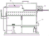
FIG. 1 is a schematic structural view of a sewage treatment filter device according to an embodiment of the present invention;
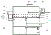
fig. 2 is a schematic structural diagram of a filtering mechanism according to an embodiment of the present invention;
fig. 3 is a schematic structural view of a filter member according to an embodiment of the present invention;
fig. 4 is a schematic structural view of a filter screen cleaning mechanism provided in an embodiment of the present invention;
fig. 5 is a schematic structural diagram of a first push plate at a first viewing angle according to an embodiment of the present invention;
fig. 6 is a schematic structural diagram of the first push plate at a second viewing angle according to the embodiment of the present invention;
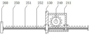
fig. 7 is a schematic structural view of the telescopic push rod and the driving gear provided by the embodiment of the present invention;
fig. 8 is a schematic structural view of a backwashing mechanism provided in an embodiment of the present invention.
In the figure: 10-a filtering mechanism; 110-a base; 120-equipment box; 130-a filter tank; 131-a chute; 132-a dirt outlet; 140-a filter element; 141-a frame; 142-a filter element; 143-filtration pores; 144-a handle; 150-a sewage pipe; 160-a drain pipe; 20-a filter screen cleaning mechanism; 210-a first motor; 220-a lifting kit; 221-a screw rod; 222-a threaded sleeve; 230-a first pusher plate; 231-a dredging column; 232-water through hole; 233-slide block; 240-a drive gear; 241-a protective box; 250-a telescopic push rod; 251-a spur rack; 252-a limit bump; 260-a second pusher plate; 270-a dirt collection piece; 271-dirt collecting frame; 272-a dirt collecting basket; 273-return pipe; 30-a flushing mechanism; 310-a water pump; 320-a water inlet pipe; 330-a water conveying pipe; 340-connecting a hose; 350-a spray head; 360-superfine metal filter screen.
Detailed Description
To make the objects, technical solutions and advantages of the embodiments of the present invention clearer, the drawings of the embodiments of the present invention are combined to clearly and completely describe the technical solutions of the embodiments of the present invention, and obviously, the described embodiments are some embodiments of the present invention, not all embodiments. Based on the embodiments in the present invention, all other embodiments obtained by a person skilled in the art without creative work belong to the protection scope of the present invention.
Thus, the following detailed description of the embodiments of the present invention, presented in the accompanying drawings, is not intended to limit the scope of the invention, as claimed, but is merely representative of selected embodiments of the invention. Based on the embodiments in the present invention, all other embodiments obtained by a person skilled in the art without creative work belong to the protection scope of the present invention.
It should be noted that: like reference numbers and letters refer to like items in the following figures, and thus, once an item is defined in one figure, it need not be further defined and explained in subsequent figures.
In the description of the present invention, it is to be understood that the terms "center", "longitudinal", "lateral", "length", "width", "thickness", "upper", "lower", "front", "rear", "left", "right", "vertical", "horizontal", "top", "bottom", "inner", "outer", "clockwise", "counterclockwise", and the like indicate orientations or positional relationships based on the orientations or positional relationships shown in the drawings, and are only for convenience of description and to simplify the description, but do not indicate or imply that the device or element referred to must have a particular orientation, be constructed and operated in a particular orientation, and therefore should not be construed as limiting the present invention.
Furthermore, the terms "first", "second" and "first" are used for descriptive purposes only and are not to be construed as indicating or implying relative importance or implicitly indicating the number of technical features indicated. Thus, a feature defined as "first" or "second" may explicitly or implicitly include one or more of that feature. In the description of the present invention, "a plurality" means two or more unless specifically limited otherwise.
In the present invention, unless otherwise expressly stated or limited, the terms "mounted," "connected," and "fixed" are to be construed broadly and may, for example, be fixedly connected, detachably connected, or integrally formed; either directly or indirectly through intervening media, either internally or in any other relationship. The specific meaning of the above terms in the present invention can be understood according to specific situations by those skilled in the art.
In the present disclosure, unless expressly stated or limited otherwise, the first feature "on" or "under" the second feature may comprise direct contact between the first and second features, or may comprise contact between the first and second features not directly. Also, the first feature being "on," "above" and "over" the second feature includes the first feature being directly on and obliquely above the second feature, or merely indicating that the first feature is at a higher level than the second feature. A first feature being "under," "below," and "beneath" a second feature includes the first feature being directly under and obliquely below the second feature, or simply meaning that the first feature is at a lesser elevation than the second feature.
Examples
Referring to fig. 1-8, the present invention provides a technical solution: a sewage treatment filter device comprises a filter mechanism 10 and a filter screen cleaning mechanism 20.
Referring to fig. 2 and 3, the filtering mechanism 10 includes a base 110, an equipment box 120, a filtering box 130 and a filtering element 140, the equipment box 120 is fixedly connected to the base 110, the equipment box 120 is fixed to the base 110 by a clamping block, an access door is opened on the front surface of the equipment box 120, the filtering box 130 is fixedly connected to the top of the equipment box 120, the filtering box 130 and the equipment box 120 are integrally formed or fixed by welding, one end of the filtering element 140 penetrates through the side wall of the filtering box 130 and the end of the filtering element is inserted into the inner wall of the filtering box 130, specifically, the filtering element 140 includes a frame 141 and a filter element 142, two sides of the frame 141 are slidably connected to the inner wall of the filtering box 130, so that the filtering element 140 can be conveniently and rapidly taken out for replacement after being damaged, the filter element 142 is clamped in the frame 141, the filter element 142 is convenient to be replaced, the filter, the handle 144 is installed at the top of the frame 141, so that the frame 141 can be conveniently assembled and disassembled, the sewage pipe 150 is arranged at the top of the filter box 130, the bottom end of one side of the filter box 130 is communicated with the drain pipe 160, and the functions of sewage inlet and filtered sewage discharge are achieved.
Referring to fig. 4, 5, and 6, the filter screen cleaning mechanism 20 includes a first motor 210, a lifting kit 220, a first push plate 230, a driving gear 240, a telescopic rod 250, and a second push plate 260, the first motor 210 is installed on an inner wall of the equipment box 120, the lifting kit 220 includes a screw rod 221 and a threaded sleeve 222, a bottom end of the screw rod 221 is vertically and rotatably connected to an inner bottom wall of the equipment box 120, the screw rod 221 is rotatably connected to upper and lower inner walls of the equipment box 120 through a bearing sleeve, a top end of the screw rod 221 rotatably penetrates through a top of the equipment box 120 and extends into the filter box 130, a connection between the screw rod 221 and the top of the equipment box 120 is sealed, and thus, sewage is prevented from leaking into the equipment box.
When the filter is specifically arranged, through the matching of a belt and a belt pulley, the output shaft of the first motor 210 is in transmission connection with the lead screw 221, the top end of the lead screw 221 is in threaded connection with the threaded sleeve 222, the lead screw 221 and the threaded sleeve 222 are in threaded connection, the first motor 210 drives the lead screw 221 to rotate forward or backward to drive the threaded sleeve 222 to move up and down, the top of the threaded sleeve 222 is fixedly connected to the middle of the lower surface of the first push plate 230, the threaded sleeve 222 and the first push plate 230 are fixed through bolts or welding, a plurality of rows of dredging columns 231 are uniformly and fixedly installed on the upper surface of the first push plate 230, the dredging columns 231 are matched with the filter holes 143 formed in the filter piece 140, a plurality of rows of water through holes 232 are formed in the first push plate 230 in a penetrating manner, when the filter holes 143 in the filter piece 140 are blocked, the first motor 210 is started to drive the, make the mediation post 231 of first push pedal 230 upper surface run through the filtration hole 143 that corresponds on the filter piece 140, can clear up the impurity or the filter residue in the filtration hole 143, first push pedal 230 both ends symmetry is fixed with slider 233, the inner wall at rose box 130 both sides is vertical set up with the spout 131 of slider 233 adaptation, slider 233 sliding connection is in spout 131, first push pedal 230 of promotion that lift external member 220 can be steady reciprocates in rose box 130, avoid first push pedal 230 to remove the in-process and take place the slope, influence the clearance effect of filtration hole 143.
Referring to fig. 4 and 7, the second push plate 260 is vertically and fixedly connected to one end of the telescopic push rod 250, the bottom end of the second push plate 260 is attached to the upper surface of the filter element 140, the other end of the telescopic push rod 250 slidably penetrates through the side wall of the filter box 130 and extends to the outside, the two side walls of the telescopic push rod 250 are both provided with a limiting bump 252, the telescopic push rod 250 is slidably connected to the side walls of the filter box 130 and the protection box 241 through the limiting bump 252 to perform a limiting function, so as to prevent the telescopic push rod 250 from tilting, the other end of the telescopic push rod 250 is configured to be in transmission connection with the driving gear 240, one side of the filter box 130 away from the driving gear 240 is provided with a dirt outlet 132, the driving gear 240 and the telescopic push rod 250 are linked to push the second push plate 260, the second push plate 260 can effectively push the impurities or filter residues cleaned in the filter element 140 and the filter hole 143, spur rack 251 meshes with drive gear 240 mutually, it drives the horizontal antedisplacement of flexible push rod 250 to mesh in spur rack 251 through drive gear 240, thereby promote second push pedal 260 with filter 140 upper surface and filter the impurity of clearing up in the hole 143 or filter residue and push through dirty piece 270 of album through a dirty mouthful 132 and collect, drive gear 240 installs in the top of rose box 130 one side, specifically, drive gear 240 rotates and connects in protection case 241, drive gear 240 is constructed the transmission and connects in the second motor, protection case 241 fixed connection is in the top of rose box 130 one side, protection case 241 passes through welded fastening with rose box 130.
Referring to fig. 4, a dirt collecting member 270 is installed on a side of the filter box 130 away from the driving gear 240, the dirt collecting member 270 is arranged to contain impurities or filter residues that are pushed into the upper surface of the ground filter member 140 and the filter holes 143 by the second pushing plate 260 through the dirt outlet 132, the dirt collecting member 270 is communicated with the side of the filter box 130 away from the driving gear 240 through the dirt outlet 132, the height of the dirt outlet 132 is greater than the height of the second pushing plate 260, so that the second pushing plate 260 is moved forward to the dirt outlet 132, specifically, the dirt collecting member 270 includes a dirt collecting frame 271, a dirt collecting basket 272 and a return pipe 273, the dirt collecting frame 271 is fixedly connected to the outer side wall of the filter box 130 below the dirt outlet 132, the dirt collecting frame 271 and the filter box 130 are fixed by welding or screws, the dirt collecting basket 272 is hung in the dirt collecting basket 271, the bottom end of the dirt collecting basket 272 is arranged in a mesh shape, the top end of the dirt collecting basket 272 is provided with a hook, the dirt collecting basket 272, return pipe 273 communicates in the dirty frame 271 bottom of collection and extends to the rose box 130 in, realize filtering the separation with sewage and impurity through the cooperation between dirty basket 272 of collection and the return pipe 273, make things convenient for the clearance of impurity.
Referring to fig. 8, the washing device 30 further includes a washing mechanism 30, the washing mechanism 30 includes a water pump 310, a water pipe 330, a connection hose 340 and a nozzle 350, the water pump 310 is installed in the equipment box 120, an input end of the water pump 310 is connected to a bottom of the filter box 130 through a water inlet pipe 320, a water inlet of the water inlet pipe 320 in the filter box 130 is covered with a superfine metal filter screen 360 to prevent impurities remained in the sewage roughly filtered by the filter 140 from blocking the nozzle 350, a bottom end of the water pipe 330 is connected to an output end of the water pump 310, a top end of the water pipe 330 penetrates through a side wall of the filter box 130 to extend into the inside, valves are disposed on the water inlet pipe 320 and the water pipe 330, the connection hose 340 is connected between a top end of the water pipe 330 and the nozzle 350, the connection hose 340 or the unfolded connection hose 340 is longer than the filter 140 and has redundancy, the, and the spraying direction of the spray head 350 is arranged towards the filtering piece 140, so that the spray head 350 can be used for pushing the impurities or filter residues cleaned up on the upper surface of the filtering piece 140 and in the filtering hole 143 through the second push plate 260 while completely washing the filtering hole 143 of the filtering piece 140 through the spray head 350 without dead angles.
Specifically, this filter equipment for sewage treatment's theory of operation: when the device is used, sewage enters the filter box 130 through the sewage pipe 150, solid impurities and filter residues in the sewage are filtered out through the filter holes 143 on the filter elements 140, the filtered sewage flows to the bottom of the filter box 130 through the water through holes 232 on the first push plate 230 and is discharged through the drain pipe 160, when the filter holes 143 on the filter elements 140 are blocked, the first motor 210 is started, the first motor 210 drives the threaded sleeve 222 to move upwards through the driving screw rod 221, so that the first push plate 230 is pushed to move upwards, the dredging columns 231 on the upper surface of the first push plate 230 penetrate through the filter holes 143 on the corresponding filter elements 140, so that impurities or filter residues in the filter holes 143 are cleaned, the driving gear 240 is driven to rotate through the second motor, the driving gear 240 is meshed with the forward rack 251 to drive the telescopic push rod 250 to move horizontally, so that the second push plate 260 is pushed to push the impurities or filter residues cleaned in the upper surface of the filter elements 140 and the filter holes 143 into the sewage collecting element 270 through the sewage outlet 132 for collection, through washing mechanism 30 messenger this device can promote the impurity or the filter residue of clearing up in filtering piece 140 upper surface and the filtration hole 143 through second push pedal 260 on one side, washes the filtration hole 143 of filtering piece 140 comprehensively on one side, does not keep the dead angle.
It should be noted that the specific model specifications of the first motor 210 and the water pump 310 need to be determined by model selection according to the actual specification of the device, and the specific model selection calculation method adopts the prior art, so detailed description is omitted.
The power supply of the first motor 210 and the water pump 310 and the principle thereof will be apparent to those skilled in the art and will not be described in detail herein.
The above description is only a preferred embodiment of the present invention and is not intended to limit the present invention, and various modifications and changes may be made by those skilled in the art. Any modification, equivalent replacement, or improvement made within the spirit and principle of the present invention should be included in the protection scope of the present invention.
Claims (10)
1. A filtering device for sewage treatment is characterized by comprising
The filtering mechanism (10) comprises a base (110), an equipment box (120), a filtering box (130) and a filtering piece (140), the equipment box (120) is fixedly connected to the base (110), the filtering box (130) is fixedly connected to the top of the equipment box (120), one end of the filtering piece (140) penetrates through the side wall of the filtering box (130) and the end part of the filtering piece is inserted into the inner wall of the filtering box (130), a sewage pipe (150) is arranged at the top of the filtering box (130), and a drain pipe (160) is communicated with the bottom end of one side of the filtering box (130);
filter screen cleaning mechanism (20), filter screen cleaning mechanism (20) includes first motor (210), goes up and down external member (220), first push pedal (230), drive gear (240), flexible push rod (250) and second push pedal (260), install first motor (210) on equipment box (120) inner wall, go up and down external member (220) including lead screw (221) and threaded sleeve (222), lead screw (221) bottom vertical rotation connect in equipment box (120) interior diapire, lead screw (221) top rotate run through in equipment box (120) top and extend to in rose box (130), first motor (210) output shaft transmission connect in lead screw (221), lead screw (221) top spiro union in threaded sleeve (222), threaded sleeve (222) top fixed connection in the lower surface middle part of first push pedal (230), a plurality of rows of dredging columns (231) are uniformly and fixedly arranged on the upper surface of the first push plate (230), the dredging column (231) is matched with a filtering hole (143) formed on the filtering piece (140), a plurality of water discharge holes (232) are arranged on the first push plate (230) in a penetrating way, the second push plate (260) is vertically and fixedly connected with one end of the telescopic push rod (250), and the bottom end of the second push plate (260) is attached to the upper surface of the filter element (140), the other end of the telescopic push rod (250) penetrates through the side wall of the filter box (130) in a sliding manner and extends to the outside, the other end of the telescopic push rod (250) is constructed to be connected with the driving gear (240) in a transmission way, the driving gear (240) is arranged at the top end of one side of the filter box (130), and a dirt collecting piece (270) is arranged on one side of the filter box (130) far away from the driving gear (240).
2. The filtering device for sewage treatment as claimed in claim 1, wherein sliding blocks (233) are symmetrically fixed at two ends of the first pushing plate (230), sliding grooves (131) adapted to the sliding blocks (233) are vertically formed in inner walls of two sides of the filtering box (130), and the sliding blocks (233) are slidably connected to the sliding grooves (131).
3. A filter device for sewage treatment according to claim 1, wherein the driving gear (240) is rotatably connected in a protective box (241), the driving gear (240) is configured to be drivingly connected to a second motor, and the protective box (241) is fixedly connected to a top end of one side of the filter box (130).
4. A sewage treatment filter unit as claimed in claim 3, wherein said telescopic push rod (250) is provided with a spur rack (251), and said spur rack (251) is engaged with said driving gear (240).
5. A sewage treatment filter unit according to claim 4, wherein the telescopic push rod (250) is provided with a limit lug (252) on both side walls, and the telescopic push rod (250) is slidably connected in the side walls of the filter box (130) and the protection box (241) through the limit lug (252).
6. A sewage treatment filter unit as claimed in claim 1, wherein said filter element (140) comprises a frame (141) and a filter element (142), said filter element (142) is clamped in said frame (141), said filter holes (143) are uniformly distributed on said filter element (142), and a handle (144) is mounted on the top of said frame (141).
7. A sewage treatment filter unit as claimed in claim 1, wherein a sewage outlet (132) is opened on one side of the filter box (130) far away from the driving gear (240), the sewage collecting member (270) is communicated with one side of the filter box (130) far away from the driving gear (240) through the sewage outlet (132), and the height of the sewage outlet (132) is greater than that of the second push plate (260).
8. A filter device for sewage treatment according to claim 7, wherein said sewage collecting member (270) comprises a sewage collecting frame (271), a sewage collecting basket (272) and a return pipe (273), said sewage collecting frame (271) is fixedly connected to the outer side wall of said filter tank (130) below said sewage outlet (132), said sewage collecting basket (272) is hung in said sewage collecting frame (271), and said return pipe (273) is communicated with the inner bottom of said sewage collecting frame (271) and extends into said filter tank (130).
9. A filtering device for sewage treatment according to claim 1, characterized by further comprising flushing means (30), the flushing mechanism (30) comprises a water pump (310), a water pipe (330), a connecting hose (340) and a spray head (350), the water pump (310) is arranged in the equipment box (120), the input end of the water pump (310) is communicated with the bottom of the filter box (130) through a water inlet pipe (320), the bottom end of the water delivery pipe (330) is communicated with the output end of the water pump (310), the top end of the water delivery pipe (330) penetrates through the side wall of the filter box (130) and extends to the inside, the connecting hose (340) is communicated between the top end of the water delivery pipe (330) and the spray head (350), the spray head (350) is fixedly connected with one side of the top of the second push plate (260) far away from the telescopic push rod (250), and the spraying direction of the spray head (350) is arranged towards the filter piece (140).
10. A filtering apparatus for sewage treatment as claimed in claim 9, wherein the water inlet pipe (320) and the water delivery pipe (330) are provided with valves, and the water inlet of the water inlet pipe (320) in the filtering tank (130) is covered with a superfine metal screen (360).
Priority Applications (1)
| Application Number | Priority Date | Filing Date | Title |
|---|---|---|---|
| CN202022416892.7U CN213668135U (en) | 2020-10-27 | 2020-10-27 | Filter equipment for sewage treatment |
Applications Claiming Priority (1)
| Application Number | Priority Date | Filing Date | Title |
|---|---|---|---|
| CN202022416892.7U CN213668135U (en) | 2020-10-27 | 2020-10-27 | Filter equipment for sewage treatment |
Publications (1)
| Publication Number | Publication Date |
|---|---|
| CN213668135U true CN213668135U (en) | 2021-07-13 |
Family
ID=76761370
Family Applications (1)
| Application Number | Title | Priority Date | Filing Date |
|---|---|---|---|
| CN202022416892.7U Active CN213668135U (en) | 2020-10-27 | 2020-10-27 | Filter equipment for sewage treatment |
Country Status (1)
| Country | Link |
|---|---|
| CN (1) | CN213668135U (en) |
Cited By (7)
| Publication number | Priority date | Publication date | Assignee | Title |
|---|---|---|---|---|
| CN113599899A (en) * | 2021-09-17 | 2021-11-05 | 合肥市正捷智能科技有限公司 | Printing and dyeing sewage circulation treatment device |
| CN114470910A (en) * | 2022-01-04 | 2022-05-13 | 宋华梅 | Water filtering and purifying circulation system capable of automatically cleaning filter residues and working method |
| CN114522932A (en) * | 2022-01-20 | 2022-05-24 | 中建八局第一建设有限公司 | Pump washing water treatment device and method |
| CN115228357A (en) * | 2022-08-19 | 2022-10-25 | 灵武市同心农业综合开发有限公司 | Seed dressing process and equipment of iron nano micro-fertilizer for pasture seeds |
| CN116832508A (en) * | 2023-08-28 | 2023-10-03 | 中建五局第三建设有限公司 | Sewage filtering device and cleaning method |
| CN117463057A (en) * | 2023-12-26 | 2024-01-30 | 山东驰盛新能源设备有限公司 | High-salt sewage treatment equipment |
| CN117643759A (en) * | 2024-01-29 | 2024-03-05 | 山西云海川环保科技有限公司 | Sewage treatment device |
-
2020
- 2020-10-27 CN CN202022416892.7U patent/CN213668135U/en active Active
Cited By (10)
| Publication number | Priority date | Publication date | Assignee | Title |
|---|---|---|---|---|
| CN113599899A (en) * | 2021-09-17 | 2021-11-05 | 合肥市正捷智能科技有限公司 | Printing and dyeing sewage circulation treatment device |
| CN114470910A (en) * | 2022-01-04 | 2022-05-13 | 宋华梅 | Water filtering and purifying circulation system capable of automatically cleaning filter residues and working method |
| CN114522932A (en) * | 2022-01-20 | 2022-05-24 | 中建八局第一建设有限公司 | Pump washing water treatment device and method |
| CN114522932B (en) * | 2022-01-20 | 2022-12-16 | 中建八局第一建设有限公司 | Pump washing water treatment device and method |
| CN115228357A (en) * | 2022-08-19 | 2022-10-25 | 灵武市同心农业综合开发有限公司 | Seed dressing process and equipment of iron nano micro-fertilizer for pasture seeds |
| CN115228357B (en) * | 2022-08-19 | 2023-09-26 | 灵武市同心农业综合开发有限公司 | Iron nanometer micro-fertilizer seed dressing process for pasture seeds and equipment thereof |
| CN116832508A (en) * | 2023-08-28 | 2023-10-03 | 中建五局第三建设有限公司 | Sewage filtering device and cleaning method |
| CN117463057A (en) * | 2023-12-26 | 2024-01-30 | 山东驰盛新能源设备有限公司 | High-salt sewage treatment equipment |
| CN117643759A (en) * | 2024-01-29 | 2024-03-05 | 山西云海川环保科技有限公司 | Sewage treatment device |
| CN117643759B (en) * | 2024-01-29 | 2024-04-12 | 山西云海川环保科技有限公司 | Sewage treatment device |
Similar Documents
| Publication | Publication Date | Title |
|---|---|---|
| CN213668135U (en) | Filter equipment for sewage treatment | |
| CN110130434B (en) | Channel long side slope dredging filter | |
| CN209985046U (en) | Building wastewater treatment device | |
| CN218281931U (en) | Can remove dust clear construction waste recovery device | |
| CN216395666U (en) | Oil gas recovery filters purification device | |
| CN210495402U (en) | Sewage filtering device | |
| CN114477668A (en) | Aeration tank return sludge treatment device | |
| CN212984036U (en) | Secondary water supply device with blowdown function | |
| CN213407923U (en) | Special dirt separator of sewage preliminary treatment | |
| CN220462500U (en) | Elevator accessory production and processing tapping machine | |
| CN218508555U (en) | Long service life's circulation water supply equipment | |
| CN112392776A (en) | Anti-clogging back washing device for sewage pump | |
| CN213100981U (en) | Industrial sewage recovery equipment | |
| CN216827493U (en) | Cleaning device for biochemical potassium production equipment | |
| CN213848656U (en) | Bubble cleaning machine | |
| CN212417108U (en) | Water treatment facilities convenient to wash | |
| CN216549688U (en) | Freshwater fish pond scrubbing device | |
| CN218188440U (en) | Water circulating device for ozone vegetable disinfection | |
| CN214344894U (en) | Oil field oil recovery filter equipment | |
| CN218130502U (en) | Protection liquid circulation collecting device with work piece waste residue is retrieved | |
| CN216195367U (en) | Municipal administration sanitation is with wasing soil pick-up car | |
| CN219272294U (en) | Novel sludge discharge device for sewage treatment | |
| CN214936156U (en) | Industrial wastewater treatment tank | |
| CN219518048U (en) | Sewage recovery device | |
| CN219710431U (en) | River mud extraction cleaning device |
Legal Events
| Date | Code | Title | Description |
|---|---|---|---|
| GR01 | Patent grant | ||
| GR01 | Patent grant |