CN213656759U - Waste incineration combustion chamber device - Google Patents
Waste incineration combustion chamber device Download PDFInfo
- Publication number
- CN213656759U CN213656759U CN202022724542.7U CN202022724542U CN213656759U CN 213656759 U CN213656759 U CN 213656759U CN 202022724542 U CN202022724542 U CN 202022724542U CN 213656759 U CN213656759 U CN 213656759U
- Authority
- CN
- China
- Prior art keywords
- burning
- burning furnace
- incinerator
- combustion chamber
- fixedly connected
- Prior art date
- Legal status (The legal status is an assumption and is not a legal conclusion. Google has not performed a legal analysis and makes no representation as to the accuracy of the status listed.)
- Active
Links
Images


Landscapes
- Incineration Of Waste (AREA)
Abstract
The utility model discloses a msw incineration combustion chamber device, which comprises a supporting pedestal and is characterized by further comprising, the up end fixedly connected with who supports the base burns burning furnace, it is used for realizing keeping sealed apron mechanism in the burning furnace to burn to be equipped with on burning furnace's the lateral wall, it is used for realizing collecting the circulation mechanism of anti-stove to burn insufficient smog in burning furnace to burn on burning furnace's the lateral wall, be equipped with the ejection of compact chamber in the support base, the ejection of compact intracavity is equipped with the ejection of compact screw rod mechanism that is used for realizing burning the convenient ejection of compact of burning furnace. The utility model discloses it is rational in infrastructure, realize burning the waste gas that produces in the burning process of burning furnace through setting up circulation mechanism, through the air-blower with waste gas secondary stove return, promote rubbish when burning in burning furnace fully, avoid the waste gas outflow to cause the pollution to the environment, realize burning impurity's cleanness in burning furnace through setting up ejection of compact screw rod mechanism, realize the convenient clearance to burning impurity through conveying screw.
Description
Technical Field
The utility model relates to a msw incineration technical field especially relates to a msw incineration combustion chamber device.
Background
The incinerator is a harmless treatment device which is commonly used for harmless treatment of medical and domestic waste products and animals. The principle is that the objects to be treated are incinerated and carbonized at high temperature by utilizing the combustion of fuels such as coal, fuel oil, fuel gas and the like so as to achieve the aim of disinfection.
When the existing garbage incinerator is used, because the burning in the incinerator is insufficient, the waste gas causes secondary pollution to the environment when being treated, and meanwhile, the waste slag generated after the burning of the existing incinerator is used is complex and laborious to clean.
SUMMERY OF THE UTILITY MODEL
The utility model aims at solving the defects existing in the prior art and providing a waste incineration combustion chamber device.
In order to achieve the above purpose, the utility model adopts the following technical scheme:
the utility model provides a waste incineration combustion chamber device, includes and supports the base, the up end fixedly connected with who supports the base burns burning furnace, it is used for realizing keeping sealed apron mechanism to burn the interior waste combustion process of burning furnace to be equipped with on the lateral wall of burning furnace, it is used for realizing collecting the circulation mechanism of anti-stove to burn insufficient smog of burning in the burning furnace to be equipped with on the lateral wall of burning furnace, be equipped with the ejection of compact chamber in the support base, the ejection of compact intracavity is equipped with the ejection of compact screw mechanism that is used for realizing the convenient ejection of compact of burning.
Preferably, the cover plate mechanism comprises a rotating cover plate which is rotatably connected to the side wall of the incinerator, the rotating cover plate and the side wall of the incinerator are both provided with fixed sleeves, two fixed sleeves are connected with fixed rods in a sliding mode, and the left end face of each fixed rod is rotatably connected with a rotating rod.
Preferably, the circulating mechanism comprises an air suction cover fixedly connected to the side wall of the incinerator, an air blower is fixedly connected to the air suction cover, an air inlet of the air blower is communicated with the air suction cover, and an air outlet connecting pipe of the air blower is communicated with the incinerator.
Preferably, the discharging screw mechanism comprises a discharging cavity arranged in the supporting base, a conveying screw is rotatably connected in the discharging cavity, and the upper end of the discharging cavity is communicated with the inner bottom of the incinerator.
Preferably, be equipped with the drive groove in the support base, the drive inslot internal rotation is connected with the worm, the axis of rotation fixed connection conveying screw of worm, the worm meshing is connected with the worm wheel, the axis of rotation of worm wheel runs through the drive groove and the end rotates and connects in the incinerator, two rotation push pedals of fixedly connected with in the axis of rotation of worm wheel, the rotation push pedal sets up in the incinerator.
Preferably, the transmission motor is fixedly connected to the side wall of the left side of the supporting base, and an output shaft of the transmission motor is connected to the supporting base in a penetrating and rotating manner and is fixedly connected to the worm rotating shaft at the tail end.
Compared with the prior art, the utility model, its beneficial effect does:
1. realize burning the waste gas that produces among the burning process of burning furnace through setting up circulation mechanism, return the stove with waste gas secondary through the air-blower, promote rubbish in burning furnace in full combustion, avoid the waste gas outflow to cause the pollution to the environment.
2. Realize the cleanness to burning impurity in the incinerator through setting up ejection of compact screw rod mechanism, realize the convenient clearance to burning impurity through conveying screw.
Drawings
FIG. 1 is a schematic view of the internal structure of a waste incineration combustion chamber device according to the present invention;
FIG. 2 is a schematic front view of a waste incineration chamber device according to the present invention;
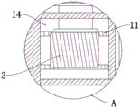
fig. 3 is an enlarged schematic view of a structure at a position a of the waste incineration combustion chamber device provided by the utility model.
In the figure: the incinerator comprises a supporting base 1, an incinerator 2, a worm 3, a rotating cover plate 4, a fixing sleeve 5, a rotating rod 6, a fixing rod 7, an air suction cover 8, a blower 9, a connecting pipe 10, a worm wheel 11, a transmission motor 12, a rotating push plate 13, a discharging cavity 14 and a conveying screw 15.
Detailed Description
In order to make the above objects, features and advantages of the present invention more comprehensible, embodiments of the present invention are described in detail below with reference to the accompanying drawings. In the following description, numerous specific details are set forth in order to provide a thorough understanding of the present invention. The present invention can be embodied in many different forms other than those specifically described herein, and it will be apparent to those skilled in the art that similar modifications can be made without departing from the spirit and scope of the invention, and it is therefore not to be limited to the specific embodiments disclosed below.
It will be understood that when an element is referred to as being "secured to" another element, it can be directly on the other element or intervening elements may also be present. When an element is referred to as being "connected" to another element, it can be directly connected to the other element or intervening elements may also be present. The terms "vertical," "horizontal," "left," "right," and the like as used herein are for illustrative purposes only and do not represent the only embodiments.
Referring to fig. 1-3, a waste incineration combustion chamber device, including supporting base 1, the up end fixedly connected with of supporting base 1 burns burning furnace 2, be equipped with on the lateral wall of burning furnace 2 and be used for realizing keeping sealed apron mechanism to burning in-process of the rubbish burning in 2, be equipped with on the lateral wall of burning furnace 2 and be used for realizing the circulation mechanism of the insufficient smog collection anti-stove of burning in 2 burning furnace, be equipped with ejection of compact chamber 14 in the supporting base 1, be equipped with the ejection of compact screw mechanism that is used for realizing burning the convenient ejection of compact of 2 burning furnace in the ejection of compact chamber 14.
The utility model discloses in, apron mechanism is including rotating the rotation apron 4 of connection on burning furnace 2 lateral wall, rotates apron 4 and all is equipped with fixed sleeve 5 on burning furnace 2's the lateral wall, and sliding connection has dead lever 7 in two fixed sleeve 5, and the left side terminal surface of dead lever 7 rotates and is connected with dwang 6.
The circulating mechanism comprises an air suction cover 8 fixedly connected to the side wall of the incinerator 2, an air blower 9 is fixedly connected to the air suction cover 8, an air inlet of the air blower 9 is communicated with the air suction cover 8, an air outlet connecting pipe 10 of the air blower 9 is connected with the incinerator 2, and the connecting pipe 10 is communicated with the air outlet.
The discharging screw mechanism comprises a discharging cavity 14 arranged in the supporting base 1, a conveying screw 15 is rotationally connected in the discharging cavity 14, and the upper end of the discharging cavity 14 is communicated with the inner bottom of the incinerator 2.
Be equipped with the transmission groove in the support base 1, the transmission inslot internal rotation is connected with worm 3, the axis of rotation fixed connection conveyor screw 15 of worm 3, the meshing of worm 3 is connected with worm wheel 11, the axis of rotation of worm wheel 11 runs through the transmission groove and end-to-end rotation connects in burning furnace 2, two rotation push pedals 13 of fixedly connected with in the axis of rotation of worm wheel 11, rotate push pedal 13 and set up in burning furnace 2.
Fixedly connected with drive motor 12 on the left side lateral wall of support base 1, the output shaft of drive motor 12 runs through to rotate and connects in supporting base 1 and terminal fixed connection worm 3 axis of rotation.
When the utility model is used, as shown in figures 1-3, after the garbage in the incinerator 2 is filled, the rotating cover plate 4 is rotated, the fixed rod 7 is pushed to slide and clamp in the fixed sleeve 5, then the rotating rod 6 is rotated to lock the rotating cover plate 4, the feed inlet of the incinerator 2 is kept closed, the outflow of waste gas is prevented, the blower 9 is started during the combustion process, the waste gas is sucked into the blower 9 through the air suction cover 8 and then is injected into the incinerator 2 again through the connecting pipe 10, the combustion intensity is improved, simultaneously, the waste gas is processed by secondary combustion, after the waste is combusted, the transmission motor 12 is started to drive the worm 3 to be meshed with the worm wheel 11, and drives the rotation of the conveying screw 15 to drive the rotation of the rotating push plate 13 in the incinerator 2, so as to drive the combustion impurities to be discharged through the discharging cavity 14, and finally the combustion impurities are discharged out of the incinerator 2 under the action of the conveying screw 15.
The above, only be the concrete implementation of the preferred embodiment of the present invention, but the protection scope of the present invention is not limited thereto, and any person skilled in the art is in the technical scope of the present invention, according to the technical solution of the present invention and the utility model, the concept of which is equivalent to replace or change, should be covered within the protection scope of the present invention.
Claims (6)
1. The utility model provides a waste incineration combustion chamber device, is including supporting base (1), its characterized in that, the up end fixedly connected with who supports base (1) burns burning furnace (2), it keeps sealed apron mechanism to be equipped with on the lateral wall of burning furnace (2) to be used for realizing burning in the burning furnace (2) rubbish combustion process, it is used for realizing the circulation mechanism who burns the incomplete smog collection reverberatory furnace in burning furnace (2) to be equipped with on the lateral wall of burning furnace (2), be equipped with discharge chamber (14) in supporting base (1), be equipped with the ejection of compact screw mechanism that is used for realizing burning the convenient ejection of compact of burning furnace (2) in discharge chamber (14).
2. A waste incineration combustion chamber device according to claim 1, characterized in that the cover plate mechanism comprises a rotary cover plate (4) rotatably connected to the side wall of the incinerator (2), the rotary cover plate (4) and the side wall of the incinerator (2) are provided with fixing sleeves (5), two fixing sleeves (5) are slidably connected with a fixing rod (7), and the left end face of the fixing rod (7) is rotatably connected with a rotary rod (6).
3. A waste incineration combustion chamber arrangement according to claim 1, characterized in that the circulating mechanism comprises an air suction hood (8) fixedly connected to the side wall of the incinerator (2), a blower (9) is fixedly connected to the air suction hood (8), the air inlet of the blower (9) is communicated with the air suction hood (8), the air outlet of the blower (9) is connected with a pipe (10), and the pipe (10) is communicated with the incinerator (2).
4. A waste incineration combustion chamber device according to claim 1, characterized in that the discharging screw mechanism comprises a discharging cavity (14) arranged in the supporting base (1), a conveying screw (15) is rotatably connected in the discharging cavity (14), and the upper end of the discharging cavity (14) is communicated with the inner bottom of the incinerator (2).
5. A waste incineration combustion chamber device according to claim 4, characterized in that a transmission groove is arranged in the supporting base (1), a worm (3) is rotatably connected in the transmission groove, the rotating shaft of the worm (3) is fixedly connected with a conveying screw (15), the worm (3) is engaged with a worm wheel (11), the rotating shaft of the worm wheel (11) penetrates through the transmission groove and the tail end of the worm wheel is rotatably connected in the incinerator (2), two rotating push plates (13) are fixedly connected to the rotating shaft of the worm wheel (11), and the rotating push plates (13) are arranged in the incinerator (2).
6. A waste incineration combustion chamber device according to claim 5, characterized in that a transmission motor (12) is fixedly connected to the left side wall of the supporting base (1), the output shaft of the transmission motor (12) is connected in the supporting base (1) in a penetrating and rotating manner, and the tail end of the transmission motor is fixedly connected with the rotating shaft of the worm (3).
Priority Applications (1)
| Application Number | Priority Date | Filing Date | Title |
|---|---|---|---|
| CN202022724542.7U CN213656759U (en) | 2020-11-20 | 2020-11-20 | Waste incineration combustion chamber device |
Applications Claiming Priority (1)
| Application Number | Priority Date | Filing Date | Title |
|---|---|---|---|
| CN202022724542.7U CN213656759U (en) | 2020-11-20 | 2020-11-20 | Waste incineration combustion chamber device |
Publications (1)
| Publication Number | Publication Date |
|---|---|
| CN213656759U true CN213656759U (en) | 2021-07-09 |
Family
ID=76685526
Family Applications (1)
| Application Number | Title | Priority Date | Filing Date |
|---|---|---|---|
| CN202022724542.7U Active CN213656759U (en) | 2020-11-20 | 2020-11-20 | Waste incineration combustion chamber device |
Country Status (1)
| Country | Link |
|---|---|
| CN (1) | CN213656759U (en) |
-
2020
- 2020-11-20 CN CN202022724542.7U patent/CN213656759U/en active Active
Similar Documents
| Publication | Publication Date | Title |
|---|---|---|
| CN205299540U (en) | Waste incinerator for refuse treatment | |
| CN111237778A (en) | Ash cleaning robot and method for garbage incineration | |
| CN109237484A (en) | A kind of environment protection garbage incineration is without fume treating device | |
| CN213656759U (en) | Waste incineration combustion chamber device | |
| CN112413602A (en) | Household garbage incineration device and incineration method | |
| CN214536211U (en) | High-efficiency incinerator for waste incineration | |
| CN111006215A (en) | Solid waste treatment and recovery device | |
| CN109780543A (en) | A kind of innoxious animal incinerator | |
| CN210568465U (en) | Energy-concerving and environment-protective articles for daily use waste incineration device | |
| CN209926358U (en) | Chemical waste incineration device | |
| CN220379673U (en) | Incinerator for garbage classification incineration treatment | |
| CN208025529U (en) | A kind of danger wastes incinerating and treating device | |
| CN220366414U (en) | Garbage incinerator with sufficient garbage treatment | |
| CN216953073U (en) | Solid waste incinerator | |
| CN213656756U (en) | Domestic garbage incinerator | |
| CN213912798U (en) | A adsorb-desorption all-in-one for burning furnace organic waste gas handles | |
| CN220728246U (en) | Mobile medical treatment and household garbage treatment system | |
| CN211925760U (en) | Medical waste treatment device | |
| CN212901510U (en) | Garbage turning device of self-combustion garbage pyrolysis furnace | |
| CN215541343U (en) | Steel solid-state garbage incineration slag treatment device | |
| CN212273998U (en) | Energy-saving waste incinerator | |
| CN214791146U (en) | Multifunctional incinerator | |
| CN220061757U (en) | Medical waste treatment device | |
| CN213577489U (en) | Environment-friendly garbage incinerator | |
| CN215808530U (en) | Msw incineration device for municipal administration |
Legal Events
| Date | Code | Title | Description |
|---|---|---|---|
| GR01 | Patent grant | ||
| GR01 | Patent grant |