CN213652806U - Adjustable cloth guide device for loom - Google Patents
Adjustable cloth guide device for loom Download PDFInfo
- Publication number
- CN213652806U CN213652806U CN202021873559.2U CN202021873559U CN213652806U CN 213652806 U CN213652806 U CN 213652806U CN 202021873559 U CN202021873559 U CN 202021873559U CN 213652806 U CN213652806 U CN 213652806U
- Authority
- CN
- China
- Prior art keywords
- vertical plate
- cloth guide
- movable
- guide roller
- loom
- Prior art date
- Legal status (The legal status is an assumption and is not a legal conclusion. Google has not performed a legal analysis and makes no representation as to the accuracy of the status listed.)
- Active
Links
Images


Landscapes
- Looms (AREA)
Abstract
The utility model discloses an adjustable cloth guiding device for a loom, which comprises a bottom plate, a fixed vertical plate is fixedly arranged at one side position of the upper surface of the bottom plate, a movable vertical plate parallel to the fixed vertical plate is arranged at the other side position of the upper surface of the bottom plate, a movable window I and a movable window II which correspond to the movable vertical plate are arranged at the fixed vertical plate and the movable window I in the thickness direction of the movable vertical plate, a bearing seat I which can reciprocate in the vertical direction is arranged at the fixed vertical plate and the movable window I of the movable vertical plate, and a bearing seat II which can reciprocate in the horizontal direction is arranged at the fixed vertical plate and the movable window II of the movable vertical plate, the utility model has reasonable design structure and convenient use, can properly adjust the tightness and the tension of cloth according to the needs of weaving equipment in the actual process, meets the adjustment needs, and also can meet the cloth guiding requirements of cloth with different sizes, has wide application range and low cost.
Description
Technical Field
The utility model belongs to the technical field of the loom is led cloth device and is designed, concretely relates to lead cloth device with adjustable be used for loom.
Background
Textile machines are the various mechanical devices required to process natural or chemical fibers into textile products. The different fibers such as cotton, hemp, silk and wool are processed into textiles by different procedures, and the required machines are various and various. Textile machines are generally classified according to the production process and can be divided into: spinning equipment, weaving equipment, printing and dyeing equipment, finishing equipment, chemical fiber spinning equipment, reeling equipment and non-woven fabric equipment. Spinning equipment is divided into two categories, short fiber processing and long fiber processing. Both the printing and dyeing equipment and the finishing equipment comprise cloth guide devices, and the cloth guide devices achieve the guide effect on cloth and fabrics. The cloth guide device is composed of a plurality of cloth guide rollers, cloth and fabric are guided along the cloth guide rollers, but the positions of the cloth guide rollers are fixed, and the tightness and the tension of the cloth cannot be adjusted. The position of the guide roller of part of the cloth guide device can be adjusted, but the position adjustment is realized by the driving of the cylinder and the motor, the structure is more complex, and the cost is higher. In addition, when the cloth guide roller is installed in the existing cloth guide device, only the cloth guide roller with a fixed length can be installed, and the cloth guide device cannot be used universally in different weaving equipment and is very inconvenient.
Disclosure of Invention
The utility model discloses a solve above-mentioned technical problem, provide a lead cloth device with adjustable be used for loom, its project organization is reasonable, convenient to use, can according to the equipment needs of weaving in the actual process, carries out appropriate adjustment to the elasticity and the tension of cloth, satisfies the needs of adjustment, also can satisfy the cloth demand of leading of not unidimensional cloth, application scope is extensive, and low cost.
The utility model adopts the technical proposal that: the utility model provides a lead cloth device with adjustable be used for loom, comprising a base plate, the last surface one side position fixed mounting of bottom plate has fixed riser, the other one side position of the upper surface of bottom plate installs the activity riser that parallels with fixed riser, fixed riser and the activity window two that corresponds with activity riser thickness direction all set up the position, fixed riser is equipped with bearing frame one that can be at vertical direction reciprocating motion with the activity window one position of activity riser, fixed riser is equipped with bearing frame two that can be at horizontal direction reciprocating motion with the activity window two positions of activity riser, be provided with the fabric guide roller one that can dismantle the connection between two bearing frame one, be provided with the fabric guide roller two that can dismantle the connection between two bearing frame two, fabric guide roller one and the mutual parallel arrangement in center of fabric guide roller two.
Guide grooves are formed in the two side faces of the first bearing seat and the second bearing seat, and the width of each guide groove is the same as that of the fixed vertical plate and that of the movable vertical plate.
The center of the first bearing seat is in threaded connection with a first screw rod, and the end of the first screw rod is mounted at the root of the first movable window through a bearing.
The center of the second bearing seat is in threaded connection with a second screw rod, and the end of the second screw rod is mounted at the root of the second movable window through a bearing.
And the cross section of the outer end of the connecting shaft is in a regular quadrilateral structure.
The structure of the first cloth guide roller is the same as that of the second cloth guide roller, connecting holes with cross sections in a regular quadrilateral structure are formed in the center positions of two ends of the first cloth guide roller, and the connecting holes are the same as the regular quadrilateral on the connecting shafts in size.
The upper surface position of bottom plate is equipped with two T type grooves that are parallel to each other, has placed T type piece in the T type groove, and T type piece center is seted up threaded hole, and the activity riser passes through bolted connection in the threaded hole of T type piece.
When the adjustable cloth guide device for the loom is used, a bolt for positioning a movable vertical plate is unscrewed, so that the movable vertical plate can move relative to a fixed vertical plate, after the distance between the fixed vertical plate and the movable vertical plate is adjusted to a proper position, a cloth guide roller I and a cloth guide roller II with equal length are installed between the two vertical plates, when the adjustable cloth guide device is specifically installed, connecting holes at two ends of the cloth guide roller I are correspondingly installed at the position of a connecting shaft, after the installation is finished, the position of the movable vertical plate is adjusted again, the cloth guide roller I and the cloth guide roller II are prevented from falling, the bolt is screwed, and the installation of the cloth guide roller I and the cloth guide roller II is finished; when the cloth guide device is used, the positions of the first cloth guide roller and the second cloth guide roller can be adjusted according to actual requirements, the height position of the first cloth guide roller is adjusted through the first screw rod, and the horizontal position of the second cloth guide roller is adjusted through the second screw rod, so that the requirements for adjusting the tightness and the tension of cloth are met.
A fixed vertical plate is fixedly arranged at one side of the upper surface of the bottom plate, and a movable vertical plate parallel to the fixed vertical plate is arranged at the other side of the upper surface of the bottom plate; the purpose of this is: can be convenient for adjust the interval between fixed riser and the activity riser to satisfy the dismouting demand of different length fabric guide rollers, satisfy the cloth fabric guide demand of different size requirements then, improve application scope.
The fixed vertical plate and the movable vertical plate are provided with a first movable window and a second movable window which correspond to each other in position in the thickness direction of the movable vertical plate, a first bearing seat capable of reciprocating in the vertical direction is arranged at the first movable window of the fixed vertical plate and the movable vertical plate, and a second bearing seat capable of reciprocating in the horizontal direction is arranged at the second movable window of the fixed vertical plate and the movable vertical plate; the purpose of this is: the position that can be convenient for fabric guide roller one and fabric guide roller two is adjusted to can carry out appropriate adjustment to the elasticity and the tension of cloth at the fabric guide in-process, satisfy the needs of actual work.
A first cloth guide roller which is detachably connected is arranged between the two first bearing seats, a second cloth guide roller which is detachably connected is arranged between the two second bearing seats, and the centers of the first cloth guide roller and the second cloth guide roller are arranged in parallel; the purpose of this is: the detachable connection of the cloth guide roller I and the cloth guide roller II can facilitate disassembly, assembly and replacement, and is suitable and convenient.
The utility model has the advantages that:
the utility model relates to a rational in infrastructure, convenient to use can carry out appropriate adjustment to the elasticity and the tension of cloth according to the equipment needs of weaving in the actual process, satisfies the needs of adjustment, also can satisfy not unidimensional cloth lead the cloth demand, and application scope is extensive, and low cost.
Drawings
Fig. 1 is a front view of the present invention;
fig. 2 is a top view of the present invention;
fig. 3 is a side view of the present invention;
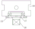
FIG. 4 is a view showing an installation structure of the connecting shaft of the present invention;
fig. 5 is a structural diagram of the first cloth guide roller of the present invention.
The labels in the figure are: 1. a base plate; 2. fixing the vertical plate; 3. a cloth guide roller I; 4. a cloth guide roller II; 5. a movable vertical plate; 6. a first bearing seat; 7. a first movable window; 8. a horizontal frame; 9. a first screw rod; 10. a vertical frame; 11. a second movable window; 12. a second screw rod; 13. a bolt; 14. a T-shaped groove; 15. an end cap; 16. a connecting shaft; 17. a nut; 18. a guide groove; 19. connecting holes; 20. anti-skid lines; 21. and a second bearing seat.
Detailed Description
The following detailed description of the embodiments of the present invention will be made with reference to the accompanying drawings.
As shown in the figure, a lead cloth device with adjustable be used for loom, comprising a base plate 1, bottom plate 1's upper surface one side position fixed mounting has fixed riser 2, the other side position of upper surface of bottom plate 1 installs the activity riser 5 that parallels with fixed riser 2, fixed riser 2 and the thickness direction with activity riser 5 all offer the activity window 7 and the activity window two 11 that the position corresponds, fixed riser 2 is equipped with bearing frame one 6 that can be at vertical direction reciprocating motion with activity window one 7 position of activity riser 5, fixed riser 2 is equipped with bearing frame two 21 that can be at horizontal direction reciprocating motion with activity window two 11 positions of activity riser 5, be provided with the cloth guide roller one 3 that can dismantle the connection between two bearing frame one 6, be provided with the cloth guide roller two 4 that can dismantle the connection between two bearing frame two 21, cloth guide roller one 3 and cloth guide roller two 4's center parallel arrangement each other.
The center position threaded connection of bearing frame 6 has lead screw 9, and the tip of lead screw 9 passes through the bearing and installs the root position at activity window 7, and wherein, a horizontal stand 8 is installed to the top of fixed riser 2 and activity riser 5, and the upper end of lead screw 9 passes through the bearing and installs on horizontal stand 8 to run through horizontal stand 8 and extend to horizontal stand 8 top position, under the circumstances of rotating lead screw 9, can realize the upper and lower drive to bearing frame 6.
The center position of the second bearing seat 21 is in threaded connection with a second screw rod 12, the end part of the second screw rod 12 is installed at the root position of the second movable window 11 through a bearing, wherein a vertical frame 10 is installed at the side positions of the fixed vertical plate 2 and the movable vertical plate 5, the second screw rod 12 is connected with the vertical frame 10 through the bearing, the second screw rod 12 extends to the outer position of the vertical frame 10, and the second screw rod 12 is used for driving the second bearing seat 21 in the horizontal direction under the condition that the second screw rod 12 is rotated.
A connecting shaft 16 is installed at the end portions of the first bearing seat 6 and the second bearing seat 21, the connecting shaft 16 is installed on the first bearing seat 6 and the second bearing seat 21 through bearings, the cross section of the outer end of the connecting shaft 16 is of a regular quadrilateral structure, specifically, the connecting shaft 16 is installed at the inner positions of the first bearing seat 6 and the second bearing seat 21 through bearings, and after the connecting shaft 16 is fixed through a nut 17, the outer rings of the bearings are compressed through installing end covers 15 on the first bearing seat 6 and the second bearing seat 21, so that the axial fixing of the connecting shaft 16 is achieved.
The structure of the first cloth guide roller 3 is the same as that of the second cloth guide roller 4, the center positions of the two ends of the first cloth guide roller 3 are provided with connecting holes 19 with cross sections in a regular quadrilateral structure, the size of each connecting hole 19 is the same as that of a regular quadrilateral on the connecting shaft 16 so as to realize the rapid assembly of the first cloth guide roller 3 and the second cloth guide roller 4, and the outer diameter surfaces of the first cloth guide roller 3 and the second cloth guide roller 4 are provided with anti-skid grains 20 so as to increase the friction force between the guide rollers and cloth in the working process and improve the guiding capacity.
The upper surface position of bottom plate 1 is equipped with two T type grooves 14 that are parallel to each other, has placed T type piece in T type groove 14, and threaded hole is seted up at T type piece center, and movable riser 5 passes through the threaded hole of bolt 13 connection at T type piece.
When the adjustable cloth guide device for the loom is used, the bolt 13 for positioning the movable vertical plate 5 is unscrewed, so that the movable vertical plate 5 can move relative to the fixed vertical plate 2, after the distance between the fixed vertical plate 2 and the movable vertical plate 5 is adjusted to a proper position, the cloth guide roller I3 and the cloth guide roller II 4 which are equal in length are installed between the two vertical plates, during specific installation, the connecting holes 19 at the two ends of the cloth guide roller I3 are correspondingly installed at the position of the connecting shaft 16, after the installation is completed, the position of the movable vertical plate 5 is adjusted again, the cloth guide roller I3 and the cloth guide roller II 4 are prevented from falling, the bolt 13 is screwed, and the installation of the cloth guide roller I3 and the cloth guide roller II 4 is completed; when the cloth guide device is used, the positions of the first cloth guide roller 3 and the second cloth guide roller 4 can be adjusted according to actual requirements, the height position of the first cloth guide roller 3 is adjusted through the first screw rod 9, and the horizontal position of the second cloth guide roller 4 is adjusted through the second screw rod 12, so that the requirements for adjusting the tightness and the tension of cloth are met.
Claims (7)
1. An adjustable cloth guider for loom, its characterized in that: the vertical cloth guide device comprises a base plate, a fixed vertical plate is fixedly arranged at one side of the upper surface of the base plate, a movable vertical plate parallel to the fixed vertical plate is arranged at the other side of the upper surface of the base plate, a first movable window and a second movable window which correspond to each other in position are arranged in the thickness direction of the fixed vertical plate and the movable vertical plate, a first bearing seat capable of moving in the vertical direction in a reciprocating mode is arranged at one position of the first movable window of the fixed vertical plate and the movable vertical plate, a second bearing seat capable of moving in the horizontal direction in a reciprocating mode is arranged at the second position of the second movable window of the fixed vertical plate and the movable vertical plate, a first cloth guide roller capable of being detachably connected is arranged between the first two bearing seats, and a second cloth guide roller.
2. The adjustable cloth guide device for the loom of claim 1, wherein: guide grooves are formed in the positions of two side faces of the first bearing seat and the second bearing seat, and the width of each guide groove is the same as that of the fixed vertical plate and that of the movable vertical plate.
3. The adjustable cloth guide device for the loom of claim 1, wherein: the center of the first bearing seat is in threaded connection with a first screw rod, and the end of the first screw rod is installed at the root of the first movable window through a bearing.
4. The adjustable cloth guide device for the loom of claim 1, wherein: the center of the second bearing seat is in threaded connection with a second screw rod, and the end of the second screw rod is mounted at the root of the second movable window through a bearing.
5. The adjustable cloth guide device for the loom of claim 1, wherein: and the cross section of the outer end of the connecting shaft is in a regular quadrilateral structure.
6. The adjustable cloth guide device for the loom of claim 5, wherein: the structure of the first cloth guide roller is the same as that of the second cloth guide roller, connecting holes with cross sections in a regular quadrilateral structure are formed in the center positions of two ends of the first cloth guide roller, and the connecting holes are the same as the regular quadrilateral on the connecting shafts in size.
7. The adjustable cloth guide device for the loom of claim 1, wherein: the upper surface position of bottom plate is equipped with two T type grooves that are parallel to each other, has placed T type piece in the T type groove, and T type piece center is seted up threaded hole, and the activity riser passes through bolted connection in the threaded hole of T type piece.
Priority Applications (1)
| Application Number | Priority Date | Filing Date | Title |
|---|---|---|---|
| CN202021873559.2U CN213652806U (en) | 2020-09-01 | 2020-09-01 | Adjustable cloth guide device for loom |
Applications Claiming Priority (1)
| Application Number | Priority Date | Filing Date | Title |
|---|---|---|---|
| CN202021873559.2U CN213652806U (en) | 2020-09-01 | 2020-09-01 | Adjustable cloth guide device for loom |
Publications (1)
| Publication Number | Publication Date |
|---|---|
| CN213652806U true CN213652806U (en) | 2021-07-09 |
Family
ID=76695092
Family Applications (1)
| Application Number | Title | Priority Date | Filing Date |
|---|---|---|---|
| CN202021873559.2U Active CN213652806U (en) | 2020-09-01 | 2020-09-01 | Adjustable cloth guide device for loom |
Country Status (1)
| Country | Link |
|---|---|
| CN (1) | CN213652806U (en) |
-
2020
- 2020-09-01 CN CN202021873559.2U patent/CN213652806U/en active Active
Similar Documents
| Publication | Publication Date | Title |
|---|---|---|
| CN108178025B (en) | A kind of fabric winding roller | |
| CN105129484B (en) | A kind of cloth guider | |
| CN111424356B (en) | Yarn drafting hairiness removing equipment | |
| CN213652806U (en) | Adjustable cloth guide device for loom | |
| CN210763656U (en) | Colored fiber yarn guiding device for textile machinery | |
| CN209224017U (en) | A kind of weaving roller collar mounting platform regulating mechanism | |
| CN112430934A (en) | Efficient dip-dyeing equipment for textile yarns and dip-dyeing method thereof | |
| CN212103162U (en) | Warp traction machine for oxford production | |
| CN211921942U (en) | Driving device for small-pressure lower compression roller of refiner | |
| CN111304798B (en) | Textile yarn carding and processing system | |
| CN209890818U (en) | Yarn guide frame for producing polyester staple fibers | |
| CN210884484U (en) | Weaving device convenient to adjust wind-up roll | |
| CN221234990U (en) | Flattening device for yarn winding | |
| CN112408098A (en) | Automatic winding method for cotton textile yarns | |
| CN111560698A (en) | Needle bed structure for warp knitting machine | |
| CN201588025U (en) | Pressure roll device for planar drafting back zone of ring spinning frame | |
| CN110550496A (en) | A soft clamping device of inlet wire for weaving machine | |
| CN221093188U (en) | Winding displacement device for spinning tightness processing | |
| CN219951329U (en) | Drafting machine convenient for adjusting pressure roller | |
| CN2397132Y (en) | Sley | |
| CN211231464U (en) | Automatic tensioning structure for spinning | |
| CN213835679U (en) | Adjustable material guide device of textile drawing frame | |
| CN220597743U (en) | High-performance fiber high-speed spinning network device | |
| CN215887394U (en) | Waxing device is used in full wool yarn production and processing | |
| CN219216932U (en) | Polyester shuttle woven grey cloth processing machine |
Legal Events
| Date | Code | Title | Description |
|---|---|---|---|
| GR01 | Patent grant | ||
| GR01 | Patent grant |