CN213643816U - Stirring machine with rotary discharging structure for aluminum foil production - Google Patents
Stirring machine with rotary discharging structure for aluminum foil production Download PDFInfo
- Publication number
- CN213643816U CN213643816U CN202021003124.2U CN202021003124U CN213643816U CN 213643816 U CN213643816 U CN 213643816U CN 202021003124 U CN202021003124 U CN 202021003124U CN 213643816 U CN213643816 U CN 213643816U
- Authority
- CN
- China
- Prior art keywords
- fixedly connected
- close
- stirring
- sides
- stirring tank
- Prior art date
- Legal status (The legal status is an assumption and is not a legal conclusion. Google has not performed a legal analysis and makes no representation as to the accuracy of the status listed.)
- Active
Links
Images

Classifications
-
- Y—GENERAL TAGGING OF NEW TECHNOLOGICAL DEVELOPMENTS; GENERAL TAGGING OF CROSS-SECTIONAL TECHNOLOGIES SPANNING OVER SEVERAL SECTIONS OF THE IPC; TECHNICAL SUBJECTS COVERED BY FORMER USPC CROSS-REFERENCE ART COLLECTIONS [XRACs] AND DIGESTS
- Y02—TECHNOLOGIES OR APPLICATIONS FOR MITIGATION OR ADAPTATION AGAINST CLIMATE CHANGE
- Y02P—CLIMATE CHANGE MITIGATION TECHNOLOGIES IN THE PRODUCTION OR PROCESSING OF GOODS
- Y02P10/00—Technologies related to metal processing
- Y02P10/20—Recycling
Landscapes
- Mixers Of The Rotary Stirring Type (AREA)
Abstract
The utility model discloses a stirrer with a rotary discharging structure for aluminum foil production, which comprises a bottom plate, wherein the top part of the bottom plate is respectively provided with a supporting plate near the left side and the right side, a stirring tank is arranged above the bottom plate, the left side and the right side of the stirring tank are respectively and fixedly connected with one side close to the two supporting plates, the top of the stirring tank close to the left side and the right side is respectively and fixedly connected with a feed hopper, and the two feed hoppers are both communicated with the inside of the stirring tank, the top of the inner cavity of the stirring tank is provided with a first bearing, the stirring of the aluminum foil production raw materials can be realized through the mutual matching of the driving motor, the connecting block, the rotating rod and the U-shaped stirring rod, and the setting of horizontal pole and scraper blade can realize scraping the raw materials that will remain on the agitator tank inner wall and fall, makes it stir, realizes the intensive mixing of raw materials, avoids the waste of raw materials resource to can realize stirring effect well and the efficient characteristics of ejection of compact.
Description
Technical Field
The utility model relates to an aluminium foil production technical field specifically is a mixer is used in aluminium foil production with rotatory ejection of compact structure.
Background
The aluminum foil is a thermoprinting material, has the advantages of moisture resistance, air tightness, shading, abrasion resistance, fragrance retention, no toxicity, no odor and the like, and is widely used for food, beverage, cigarettes, medicines, photographic base plates, household articles for daily use and the like. In aluminium foil production process, need stir the processing, but prior art's mixer stirring effect for the aluminium foil production is poor, can not make the raw materials carry out intensive mixing, and the ejection of compact of being not convenient for takes place easily and blocks up, can not realize carrying out the ejection of compact from a plurality of directions, greatly reduced discharging efficiency, the result of use is poor. Therefore, the stirring machine for producing the aluminum foil with the rotary discharging structure is provided.
SUMMERY OF THE UTILITY MODEL
The utility model provides a technical problem lie in overcoming prior art's stirring effect poor with discharging efficiency low grade defect, provide a mixer is used in aluminium foil production with rotatory ejection of compact structure. A mixer for aluminium foil production with rotatory ejection of compact structure has characteristics such as stirring effect is good and discharging efficiency height.
In order to achieve the above object, the utility model provides a following technical scheme: a stirring machine with a rotary discharging structure for aluminum foil production comprises a bottom plate, wherein supporting plates are respectively installed at the positions, close to the left side and the right side, of the top of the bottom plate, a stirring tank is arranged above the bottom plate, the left side and the right side of the stirring tank are respectively and fixedly connected with one side, close to the two supporting plates, of the left side and the right side, of the top of the stirring tank, feeding hoppers are respectively and fixedly connected with the positions, close to the left side and the right side, of the top of the stirring tank, the two feeding hoppers are communicated with the inside of the stirring tank, a first bearing is installed at the top of an inner cavity of the stirring tank, a rotating shaft is fixedly connected with an inner ring of the first bearing, a driving motor is installed at the position, close to the middle, of the top of the stirring tank, an output shaft of the, the dwang all around be equipped with the U-shaped puddler respectively outside the four sides, and the one end that two U-shaped puddlers on the horizontal direction are close to mutually respectively with the left and right sides fixed connection of two connecting blocks to the one end that two U-shaped puddlers on the fore-and-aft direction are close to mutually respectively with the front and back both sides fixed connection of two connecting blocks, the agitator tank below is equipped with annular frame, and the annular frame left and right sides lateral wall is close to bottom department fixed connection with the inner chamber lateral wall of agitator tank respectively to annular frame is linked together with the inside of agitator tank, install the valve on the annular frame outer wall, annular frame bottom swing joint has the discharging pipe. Preferably, the department that the pivot left and right sides on the first bearing is close to the bottom is fixedly connected with horizontal pole respectively, and the one end fixedly connected with scraper blade respectively that two horizontal poles kept away from mutually, two one side that the scraper blade kept away from contacts with the inner chamber lateral wall of agitator tank is close to left and right sides department respectively. Preferably, annular frame inner chamber lateral wall is close to both sides punishment and installs two trapezoidal pieces respectively, and two trapezoidal pieces of both sides set up for the front and back, two of both sides the second bearing is all installed to one side that trapezoidal piece is close to mutually, and the equal fixedly connected with pivot of two second bearing inner circles of both sides, annular frame inner chamber lateral wall is close to both sides punishment and is equipped with the buffer board respectively, and the front and back both sides of two buffer boards respectively with the one end fixed connection that two pivots of both sides are close to mutually.
Preferably, the bottoms of the two buffer plates are fixedly connected with springs respectively, and the ends, far away from the two springs, of the two buffer plates are fixedly connected with the side wall of the inner cavity of the annular frame, close to the two sides respectively.
Preferably, the third bearing is installed respectively to both sides near the bottom department around the annular frame, and the equal fixedly connected with pivot of two third bearing inner circles, both sides are respectively with the one end fixed connection that two pivots were kept away from mutually around the discharging pipe.
Preferably, the rear side of discharging pipe is equipped with two-way threaded rod, and the one side that two backup pads are close to is close to the bottom and installs the fourth bearing respectively, and both ends respectively with two fourth bearing inner circles fixed connection about two-way threaded rod, is located the right side servo motor is installed on the right side of backup pad, and servo motor's output shaft and the pivot right-hand member fixed connection in the backup pad of right side, the department of being close to the left and right sides respectively overlaps on the two-way threaded rod and is equipped with the movable block, and the inner chamber of two movable blocks is seted up respectively with two-way threaded rod assorted screw hole, two the antetheca of movable block is close to top and bottom.
Preferably, the first rectangular blocks are installed on the front walls of the two moving blocks, the fifth bearings are installed on the front walls of the two first rectangular blocks, the rotating shafts are fixedly connected to the inner rings of the two fifth bearings, the connecting rods are fixedly connected to the front ends of the rotating shafts respectively, the second rectangular blocks are installed at the positions, close to the top and the bottom, of the rear side of the discharging pipe respectively, the sixth bearings are installed on the rear walls of the two second rectangular blocks respectively, the rotating shafts are fixedly connected to the inner rings of the sixth bearings, and the rear ends of the two rotating shafts are fixedly connected to the front walls of the two connecting rods respectively.
Compared with the prior art, the beneficial effects of the utility model are that:
1. in the technical scheme, the aluminum foil production raw materials can be stirred by the mutual matching of the driving motor, the connecting block, the rotating rod and the U-shaped stirring rod, and the arrangement of the transverse rod and the scraper can realize the scraping of the raw materials remained on the inner wall of the stirring tank, so that the raw materials are stirred, the raw materials are fully stirred, the waste of raw material resources is avoided, and the stirring effect is effectively improved; 2. In the technical scheme, the material can be discharged after being stirred by the mutual matching of the valve, the annular frame and the material discharging pipe, and the arrangement of the buffer plate and the spring can slow down the material discharging speed of the material, avoid blockage and influence on material discharging, and effectively improve the material discharging effect; 3. In this technical scheme, through mutually supporting of servo motor, movable block, two-way threaded rod and connecting rod, can realize driving the discharging pipe and rotate, realize carrying out the ejection of compact from a plurality of directions, reach the effect of the ejection of compact of being convenient for, effectual discharging efficiency and the result of use of having improved to can realize stirring effect good and the high characteristics of discharging efficiency.
Drawings
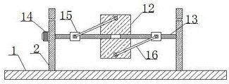
FIG. 1 is the original structure diagram of the present invention;
FIG. 2 is a rear view of the tapping pipe of FIG. 1;
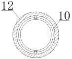
FIG. 3 is a top view of the annular frame of FIG. 1;
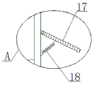
fig. 4 is an enlarged view of a portion a in fig. 1.
Reference numbers in the figures: 1. a base plate; 2. a support plate; 3. a stirring tank; 4. a drive motor; 5. connecting blocks; 6. rotating the rod; 7. a U-shaped stirring rod; 8. a cross bar; 9. a squeegee; 10. an annular frame; 11. A valve; 12. a discharge pipe; 13. a bidirectional threaded rod; 14. a servo motor; 15. a moving block; 16. a connecting rod; 17. a buffer plate; 18. a spring.
Detailed Description
The technical solutions in the embodiments of the present invention will be described clearly and completely with reference to the accompanying drawings in the embodiments of the present invention, and it is obvious that the described embodiments are only some embodiments of the present invention, not all embodiments. Based on the embodiments in the present invention, all other embodiments obtained by a person skilled in the art without creative work belong to the protection scope of the present invention.
Referring to fig. 1-4, the present invention provides a technical solution: the utility model provides a mixer is used in aluminium foil production with rotatory ejection of compact structure, includes bottom plate 1, its characterized in that: the top of the bottom plate 1 is respectively provided with a supporting plate 2 near the left side and the right side, the upper part of the bottom plate 1 is provided with a stirring tank 3, the left side and the right side of the stirring tank 3 are respectively fixedly connected with one side near the two supporting plates 2, the top of the stirring tank 3 is respectively fixedly connected with a feeding hopper near the left side and the right side, and the two feeding hoppers are communicated with the inside of the stirring tank 3, the top of the inner cavity of the stirring tank 3 is provided with a first bearing, the inner ring of the first bearing is fixedly connected with a rotating shaft, the top of the stirring tank 3 is provided with a driving motor 4 near the middle, the output shaft of the driving motor 4 is fixedly connected with the top end of the rotating shaft, the stirring tank 3 is internally provided with two connecting blocks 5, the two connecting blocks 5 are arranged up and down, a rotating rod 6 is fixedly connected between the two connecting, and the ends of the two U-shaped stirring rods 7 close to each other in the horizontal direction are respectively and fixedly connected with the left and right sides of the two connecting blocks 5, the ends of the two U-shaped stirring rods 7 close to each other in the front and back directions are respectively and fixedly connected with the front and back sides of the two connecting blocks 5, the positions of the left and right sides of the rotating shaft on the first bearing close to the bottom end are respectively and fixedly connected with a cross rod 8, the ends of the two cross rods 8 far away from each other are respectively and fixedly connected with a scraping plate 9, the sides of the two scraping plates 9 far away from each other are respectively contacted with the positions of the left and right sides of the inner cavity side wall of the stirring tank 3, the stirring of the raw materials for production can be realized through the mutual matching of the driving motor 4, the connecting blocks 5, the rotating rod 6 and the U-shaped stirring rods 7, and the arrangement of, avoid the waste of raw material resources, effectively improve the stirring effect, an annular frame 10 is arranged below the stirring tank 3, the side walls of the left side and the right side of the annular frame 10 are respectively and fixedly connected with the inner cavity side wall of the stirring tank 3 near the bottom, the annular frame 10 is communicated with the inside of the stirring tank 3, a valve 11 is arranged on the outer wall of the annular frame 10, two trapezoidal blocks are respectively arranged on the inner cavity side wall of the annular frame 10 near the two sides, the two trapezoidal blocks at the two sides are arranged in the front and back direction, a second bearing is respectively arranged at one side near the two trapezoidal blocks at the two sides, the inner rings of the two second bearings at the two sides are respectively and fixedly connected with a rotating shaft, buffer plates 17 are respectively arranged at the inner cavity side wall of the annular frame 10 near the two sides, the front side and the back side of the two buffer plates 17 are respectively and, and the end far away from the two springs 18 is fixedly connected with the side wall of the inner cavity of the annular frame 10 near the two sides respectively, the discharge of the stirred raw material can be realized through the mutual matching of the valve 11, the annular frame 10 and the discharge pipe 12, the buffer plate 17 and the springs 18 can slow down the discharge speed of the raw material, avoid the blockage and influence the discharge, and effectively improve the discharge effect, the bottom end of the annular frame 10 is movably connected with the discharge pipe 12, the positions near the bottom end of the front and back sides of the annular frame 10 are respectively provided with a third bearing, the inner rings of the two third bearings are both fixedly connected with a rotating shaft, the front and back sides of the discharge pipe 12 are respectively fixedly connected with the end far away from the two rotating shafts, the back side of the discharge pipe 12 is provided with a bidirectional threaded rod 13, the positions near the bottom of the two support plates 2 are respectively provided with a fourth bearing, and the left and, a servo motor 14 is arranged on the right side of the supporting plate 2 on the right side, an output shaft of the servo motor 14 is fixedly connected with the right end of a rotating shaft on the right supporting plate 2, moving blocks 15 are respectively sleeved on the positions, close to the left side and the right side, of the bidirectional threaded rod 13, threaded holes matched with the bidirectional threaded rod 13 are respectively formed in inner cavities of the two moving blocks 15, front walls of the two moving blocks 15 are respectively movably connected with the rear side, close to the top and the bottom, of the discharging pipe 12, first rectangular blocks are arranged on the front walls of the two moving blocks 15, fifth bearings are respectively arranged on the front walls of the two first rectangular blocks, rotating shafts are respectively and fixedly connected with inner rings of the two fifth bearings, connecting rods 16 are respectively and fixedly connected with the front ends of the two rotating shafts, second rectangular blocks are respectively arranged on the positions, close to the top, equal fixedly connected with pivot of two sixth bearing inner circles, and the rear end of two pivots respectively with two connecting rod 16's antetheca fixed connection, through servo motor 14, the movable block 15, mutually supporting of two-way threaded rod 13 and connecting rod 16, can realize driving discharging pipe 12 and rotate, realize carrying out the ejection of compact from a plurality of directions, reach the effect of the ejection of compact of being convenient for, effectual discharging efficiency and result of use have been improved, thereby can realize stirring effect good and the high characteristics of discharging efficiency, wherein driving motor 4 and servo motor 14 have control switch through external power cord electric connection respectively.
The working principle is as follows: in the technical scheme, firstly, aluminum foil production raw materials are added into a stirring tank 3 through a feed hopper, then a driving motor 4 is started, the driving motor 4 drives a connecting block 5 and a rotating rod 6 to rotate, a U-shaped stirring rod 7 rotates along with the connecting block 5, so that stirring treatment of the aluminum foil production raw materials is realized, a cross rod 8 and a scraper blade 9 rotate along with the connecting block 5, the aluminum foil production raw materials remained on the inner wall of the stirring tank 3 in the stirring process are scraped off through the rotation of the scraper blade 9, so that the stirring is performed, the raw materials are fully stirred, waste of raw material resources is avoided, the stirring effect is effectively improved, after the stirring is finished, a valve 11 is opened, the stirred aluminum foil production raw materials enter a discharge pipe 12 through an annular frame 10, and a buffer plate 17 in the annular frame 10 slows down the discharge speed of the aluminum foil production raw materials through the elastic stretching effect of a spring, avoid causing the jam, influence the ejection of compact, the effectual ejection of compact effect that has improved, start servo motor 14 after that, drive two-way threaded rod 13 through servo motor 14's positive and negative rotation and carry out clockwise or anticlockwise rotation, and two movable blocks 15 on the two-way threaded rod 13 carry out the motion in opposite directions or move from each other along with the rotation of two-way threaded rod 13, thereby realize driving discharging pipe 12 and carry out the rotation of a plurality of directions, realize discharging pipe 12 and carry out the ejection of compact from a plurality of directions, reach the effect of the ejection of compact of being convenient for, the effectual ejection of compact efficiency and result of use that have improved, thereby can realize stirring effect well with.
Although embodiments of the present invention have been shown and described, it will be appreciated by those skilled in the art that changes, modifications, substitutions and alterations can be made in these embodiments without departing from the principles and spirit of the invention, the scope of which is defined in the appended claims and their equivalents.
Claims (7)
1. The utility model provides a mixer is used in aluminium foil production with rotatory ejection of compact structure, includes bottom plate (1), its characterized in that: the stirring device is characterized in that supporting plates (2) are respectively installed at the positions, close to the left side and the right side, of the top of the bottom plate (1), a stirring tank (3) is arranged above the bottom plate (1), the left side and the right side of the stirring tank (3) are respectively fixedly connected with one side, close to the two supporting plates (2), of the left side and the right side, respectively, the top of the stirring tank (3) is respectively fixedly connected with feeding hoppers, the two feeding hoppers are communicated with the inside of the stirring tank (3), a first bearing is installed at the top of an inner cavity of the stirring tank (3), a rotating shaft is fixedly connected with an inner ring of the first bearing, a driving motor (4) is installed at the position, close to the middle, of the top of the stirring tank (3), an output shaft of the driving motor (4) is fixedly connected with the top end of the rotating shaft, two connecting blocks (5) are arranged, the top of the connecting block (5) positioned above is fixedly connected with the bottom end of the rotating shaft, U-shaped stirring rods (7) are respectively arranged outside the front side, the rear side, the left side and the right side of the rotating rod (6), and one ends of the two U-shaped stirring rods (7) in the horizontal direction, which are close to each other, are respectively fixedly connected with the left side and the right side of the two connecting blocks (5), one ends of the two U-shaped stirring rods (7) in the front-back direction, which are close to each other, are respectively and fixedly connected with the front side and the back side of the two connecting blocks (5), an annular frame (10) is arranged below the stirring tank (3), the left side wall and the right side wall of the annular frame (10) are respectively fixedly connected with the inner cavity side wall of the stirring tank (3) close to the bottom, and annular frame (10) is linked together with the inside of agitator tank (3), install valve (11) on annular frame (10) outer wall, annular frame (10) bottom swing joint has discharging pipe (12).
2. The stirring machine with the rotary discharging structure for the production of aluminum foil as claimed in claim 1, wherein: the department of the pivot left and right sides on the first bearing is close to bottom fixedly connected with horizontal pole (8) respectively, and the one end fixedly connected with scraper blade (9) respectively that two horizontal poles (8) kept away from mutually, two one side that scraper blade (9) kept away from mutually contacts with the inner chamber lateral wall of agitator tank (3) is close to left and right sides department respectively.
3. The stirring machine with the rotary discharging structure for the production of aluminum foil as claimed in claim 1, wherein: annular frame (10) inner chamber lateral wall is close to both sides punishment and installs two trapezoidal pieces respectively, and two trapezoidal pieces of both sides set up around for, two of both sides the second bearing is all installed to one side that trapezoidal piece is close to mutually, and the equal fixedly connected with pivot of two second bearing inner circles of both sides, annular frame (10) inner chamber lateral wall is close to both sides punishment and is equipped with buffer board (17) respectively, and both sides are close to one end fixed connection with two pivot axles of both sides respectively around two buffer boards (17).
4. The stirring machine with the rotary discharging structure for the production of aluminum foil as claimed in claim 3, wherein: the bottoms of the two buffer plates (17) are respectively and fixedly connected with springs (18), and the ends, far away from the two springs (18), of the two buffer plates are respectively and fixedly connected with the side wall of the inner cavity of the annular frame (10) close to the two sides.
5. The stirring machine with the rotary discharging structure for the production of aluminum foil as claimed in claim 1, wherein: the third bearing is installed respectively near bottom department in both sides around annular frame (10), and the equal fixedly connected with pivot of two third bearing inner circles, the one end fixed connection who keeps away from with two pivots respectively in both sides around discharging pipe (12).
6. The stirring machine with the rotary discharging structure for the production of aluminum foil as claimed in claim 1, wherein: the rear side of discharging pipe (12) is equipped with two-way threaded rod (13), and the one side that two backup pad (2) are close to mutually is close to bottom department and installs the fourth bearing respectively, and both ends respectively with two fourth bearing inner circle fixed connection about two-way threaded rod (13), is located the right side servo motor (14) are installed on the right side of backup pad (2), and the output shaft of servo motor (14) and the pivot right-hand member fixed connection on right backup pad (2), it is equipped with movable block (15) respectively to be close to left and right sides department on two-way threaded rod (13), and the inner chamber of two movable blocks (15) is seted up respectively with two-way threaded rod (13) assorted screw hole, two the antetheca of movable block (15) is close to top and bottom swing joint with the rear side of discharging pipe (12.
7. The stirring machine with the rotary discharging structure for the production of aluminum foil as claimed in claim 6, wherein: first rectangular blocks are installed on the front walls of the two moving blocks (15), fifth bearings are installed on the front walls of the two first rectangular blocks, rotating shafts are fixedly connected to the inner rings of the five fifth bearings, the front ends of the rotating shafts are fixedly connected with connecting rods (16) respectively, second rectangular blocks are installed at the positions, close to the top and the bottom, of the rear side of the discharging pipe (12), sixth bearings are installed on the rear walls of the two second rectangular blocks, rotating shafts are fixedly connected to the inner rings of the sixth bearings, and the rear ends of the two rotating shafts are fixedly connected with the front walls of the two connecting rods (16) respectively.
Priority Applications (1)
| Application Number | Priority Date | Filing Date | Title |
|---|---|---|---|
| CN202021003124.2U CN213643816U (en) | 2020-06-04 | 2020-06-04 | Stirring machine with rotary discharging structure for aluminum foil production |
Applications Claiming Priority (1)
| Application Number | Priority Date | Filing Date | Title |
|---|---|---|---|
| CN202021003124.2U CN213643816U (en) | 2020-06-04 | 2020-06-04 | Stirring machine with rotary discharging structure for aluminum foil production |
Publications (1)
| Publication Number | Publication Date |
|---|---|
| CN213643816U true CN213643816U (en) | 2021-07-09 |
Family
ID=76682201
Family Applications (1)
| Application Number | Title | Priority Date | Filing Date |
|---|---|---|---|
| CN202021003124.2U Active CN213643816U (en) | 2020-06-04 | 2020-06-04 | Stirring machine with rotary discharging structure for aluminum foil production |
Country Status (1)
| Country | Link |
|---|---|
| CN (1) | CN213643816U (en) |
-
2020
- 2020-06-04 CN CN202021003124.2U patent/CN213643816U/en active Active
Similar Documents
| Publication | Publication Date | Title |
|---|---|---|
| CN107583521A (en) | A kind of food processing agitating device | |
| CN214051255U (en) | Stirring processing equipment for high-viscosity materials | |
| CN108311041A (en) | A kind of Chemical Manufacture raw material mixing apparatus | |
| CN216223868U (en) | Fluorescent glue preparation device for LED lamp production | |
| CN213643816U (en) | Stirring machine with rotary discharging structure for aluminum foil production | |
| CN213348704U (en) | Mix novel high-efficient machine that mixes of storehouse adjustable | |
| CN212370155U (en) | Multi-shaft circulating material cutting type industrial raw material batching and mixing machine | |
| CN217747295U (en) | Thick broad-bean processing is with raw materials reducing mechanism | |
| CN210729234U (en) | Automatic mechanical equipment for industrial stirring | |
| CN215586082U (en) | Large-scale vertical intelligent control mixer | |
| CN207756250U (en) | A kind of recycled concrete aggregate rubblization and screening plant | |
| CN214925674U (en) | Agitating unit of mortar for building engineering | |
| CN211411876U (en) | Automatic change rabbling mechanism that dosing unit used | |
| CN210646114U (en) | Mixing device and rice crust processing equipment thereof | |
| CN112845062A (en) | Energy-conserving formula industrial material screening dust collector | |
| CN206897320U (en) | Can uniform stirring textile dyestuff mixer | |
| CN219815891U (en) | Dephosphorization agent agitating unit | |
| CN209323241U (en) | A kind of pulp crushing apparatus of corrugation paper pulp | |
| CN218637128U (en) | Novel vertical mixer | |
| CN220677624U (en) | Multistage crushing and mixing device for bio-organic fertilizer | |
| CN209985287U (en) | Stirring equipment for chemical industry with high stirring efficiency | |
| CN215388891U (en) | Fish collagen peptide gets takes off fishy smell equipment | |
| CN220633967U (en) | Shrimp slip rabbling mechanism | |
| CN203805130U (en) | Stirring machine for smashing, mixing and slicing clay | |
| CN214000009U (en) | Production concrete expanding agent loading attachment |
Legal Events
| Date | Code | Title | Description |
|---|---|---|---|
| GR01 | Patent grant | ||
| GR01 | Patent grant |