CN213643777U - Can apply high efficiency ring type glue mixer of functional additive - Google Patents
Can apply high efficiency ring type glue mixer of functional additive Download PDFInfo
- Publication number
- CN213643777U CN213643777U CN202022256130.5U CN202022256130U CN213643777U CN 213643777 U CN213643777 U CN 213643777U CN 202022256130 U CN202022256130 U CN 202022256130U CN 213643777 U CN213643777 U CN 213643777U
- Authority
- CN
- China
- Prior art keywords
- fixed
- glue
- dust
- close
- lower shell
- Prior art date
- Legal status (The legal status is an assumption and is not a legal conclusion. Google has not performed a legal analysis and makes no representation as to the accuracy of the status listed.)
- Active
Links
Images


Abstract
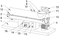
The utility model provides a high-efficiency ring-type glue mixer capable of applying functional additives, which comprises a base, wherein the top of the base is fixed with a lower shell, the top of the lower shell is rotationally connected with an upper shell through a hinge, the inner wall of the lower shell is provided with a mixing mechanism for stirring wood shavings to fully mix the glue water with the wood shavings, one end of the upper shell is fixed with a feed port, one end of the lower shell, which is far away from the feed port, is fixed with a discharge port, one side of the top of the base, which is close to the feed port, is fixed with a dust removal mechanism for removing dust generated during feeding, one side of the lower shell is fixed with a locking mechanism for locking the upper shell and the lower shell, one end of the top of the upper shell, which is close to the feed port, is fixed with a glue spraying port, the utility model can effectively complete the glue mixing work of the wood shavings, and simultaneously can be, and dust produced when the glue is stirred and the material is fed can be effectively adsorbed, and the production efficiency is improved.
Description
Technical Field
The utility model relates to a ring type glue mixer technical field especially relates to a can apply high efficiency ring type glue mixer of functional additive.
Background
The particle board keeps the unique advantages in the artificial board industry at home and abroad, glue mixing is very important in the particle board production, and the cost required by glue application amount exceeds 30 percent of the total production cost of the particle board. The glue mixing process has direct influence on the production of the shaving board and determines the quality, performance and cost of the shaving board, so that the research on the aspect of shaving board glue mixing equipment is particularly important, the most used glue mixer structural forms at present comprise a single-shaft ring type glue mixer, a double-shaft ring type glue mixer and a drum type glue mixer, and the practical production finds that the gap between a glue mixing claw and an inner wall of the glue mixer has important influence on glue mixing. If the clearance is reduced, the friction between the glue mixing claw and the inner wall can be increased, the motor power of the glue mixer is increased, the abrasion of the inner wall of the glue mixer is accelerated, and the service life of the glue mixer is shortened. Simultaneously, if the clearance increases, the wood shavings that then press close to the inner chamber receive the rubber mixing claw impetus to reduce, the wood shavings velocity of flow slows down, glue mixer output also can reduce, and press close to the wood shavings of glue mixer inner wall and the heat that the inner wall friction produced is difficult for taking away, can arouse the glue solution precuring, and traditional glue mixer can not add corresponding functional additive at the in-process of glue mixing, make the glue mixing quality not high, can produce a large amount of dusts when the wood shavings drop into glue mixer simultaneously, and traditional glue mixer can not get rid of the dust that the material of throwing produced, lead to the factory to be covered with the dust, often lead to the machine to break down because of the dust, extremely influence work efficiency.
Therefore, it is necessary to provide a high-efficiency ring-type glue mixer capable of applying functional additives to solve the above technical problems.
SUMMERY OF THE UTILITY MODEL
In order to solve the technical problem, the utility model provides a can effectively get rid of the dust that produces when throwing the material, can adjust glue mixing claw and glue mixer inner wall clearance to can add the high efficiency ring type glue mixer that can apply functional additive of functional additive at the glue mixing in-process.
The utility model provides a pair of can apply high efficiency ring type glue mixer of function auxiliary agent, the on-line screen storage device comprises a base, the top of base is fixed with down the casing, the top of casing is rotated through the hinge and is connected with the casing down, the inner wall of casing is provided with the mixing mechanism who is used for stirring wood shavings to make wood shavings intensive mixing glue down, the one end of going up the casing is fixed with the feed inlet, the one end that the feed inlet was kept away from to the casing down is fixed with the discharge gate, one side that the top of base is close to the feed inlet is fixed with the dust removal mechanism who is used for getting rid of the dust that produces when the material loading, one side of casing is fixed with the locking mechanism who is used for going up casing and casing locking down, the one end that the top of going up the casing is close to the feed inlet is fixed with the glue spout mouth.
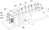
Preferably, the mixing mechanism comprises a rotating shaft, a spiral feeding blade, a sliding sleeve, a glue mixing claw, a limiting hole, a first threaded hole, a fixing bolt, a second pulley, a motor, a first pulley and a belt, wherein the inner wall of the lower shell is rotatably connected with the rotating shaft through a bearing, the spiral feeding blade is fixed on the outer wall of one end, close to the feeding hole, of the rotating shaft, the sliding sleeve is fixed on the outer wall of one end, far away from the spiral feeding blade, of the rotating shaft at equal intervals, the sliding sleeve is connected with the glue mixing claw in a sliding manner, the limiting hole is formed in the outer wall of the glue mixing claw at equal intervals, the first threaded hole is formed in one side, close to the limiting hole, of the sliding sleeve, the fixing bolt is connected with the sliding sleeve through a first threaded hole in a threaded manner, one end of the fixing bolt is sleeved with one limiting hole in the glue mixing, the one end that the base upper surface is close to the feed inlet is fixed with the motor, the output of motor is fixed with first belt pulley, first belt pulley passes through belt drive with the second belt pulley and is connected.
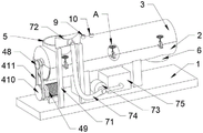
Preferably, the dust removing mechanism comprises support rods, dust hoods, dust collectors, air pipes, dust collecting boxes and doors, the support rods are fixed at one ends, close to the feeding holes, of the tops of the two support rods, the dust hoods are fixed at the tops of the two support rods, the dust collectors are fixed at the tops of the bases, dust inlet ends of the dust collectors are communicated with the dust hoods through the air pipes, the dust collecting boxes are fixed at the tops of the bases, dust outlet ends of the dust collectors are communicated with the dust collecting boxes, and the doors are rotatably connected to one sides, far away from the dust collectors, of the dust collecting boxes through hinges.
Preferably, locking mechanism includes connecting block, L type strip, second screw hole, screw rod, hand wheel and latch segment, the lateral symmetry equidistance that the casing is close to the bracing piece down is fixed with the connecting block, two the middle part of connecting block is rotated through the pivot and is connected with L type strip, the second screw hole has been seted up at the top of L type strip, L type strip has the screw rod through second screw hole threaded connection, the top of screw rod is fixed with the hand wheel, it is fixed with the latch segment to go up one side equidistance that the casing is close to the connecting block, and the screw rod cooperatees with the latch segment.
Preferably, cooling cavities are formed in the upper shell and the lower shell, water inlets are fixed to the ends, close to the discharge port, of the upper shell and the lower shell respectively, the two water inlets are communicated with the two cooling cavities respectively, water outlets are fixed to the ends, close to the feed port, of the upper shell and the lower shell respectively, and the two water outlets are communicated with the two cooling cavities respectively.
Preferably, a filter screen is fixed in the middle of the door.
Compared with the prior art, the utility model provides a can apply high efficiency ring type glue mixer of functional additive has following beneficial effect:
the utility model provides a can apply high efficiency ring type glue mixer of functional additive:
when the utility model is used, the first belt pulley is rotated by adding the wood shaving scraps at the feeding port and then the driving motor, the belt is driven to rotate, the second belt pulley is further rotated, the rotating shaft is further rotated, the spiral feeding blade is further rotated, the wood shaving scraps are driven to be pushed towards the discharging port, the wood shaving scraps are further driven to reach the glue spraying port, the glue inlet end of the glue spraying port is connected with glue pouring equipment, glue is further sprayed to the wood shaving scraps through the glue spraying port, the auxiliary agent filling port is connected with functional auxiliary agent pouring equipment, functional auxiliary agents are added to the wood shaving scraps through the auxiliary agent filling port, the glue mixing claw is continuously rotated at the same time, the wood shaving scraps are driven to be continuously mixed with the glue and the functional auxiliary agents, the mixed wood shaving scraps are further driven to move towards the discharging port under the action of the glue mixing claw and then are discharged from the discharging port, and when the wood shaving scraps are added from the feeding port, the dust collector is driven, negative pressure is formed at the end of the dust collection cover, dust generated by feeding is enabled to pass through the air pipe and then collected into the dust collection box under the effect of the dust collector, meanwhile, when glue is mixed, cooling water is added at the water inlet, the cooling water circulates in the cooling cavity and flows out from the water outlet, the effect of cooling the upper shell and the lower shell is achieved, the problem that internal glue is solidified due to friction heating of shaving scraps is avoided, when the clearance between the glue mixing claw and the inner walls of the upper shell and the lower shell needs to be adjusted, the fixing bolt is unscrewed, the glue mixing claw is further vertically moved up and down, the glue mixing claw is vertically moved along the sliding sleeve, the distance between the glue mixing claw and the inner walls of the upper shell and the lower shell is adjusted, when the glue mixing claw is adjusted to a required position, the fixing bolt tightly abuts against the limiting hole through screwing the fixing bolt, when the glue mixing machine needs to be opened, and then make screw rod and second screw hole separation, and then rotate L shaped strip for L shaped strip rotates to the lower extreme of latch segment, and then rotates the casing, makes the mixer open, the utility model discloses the glue mixing work that can effectual completion wood shavings can be convenient for adjust the clearance of glue mixing claw and mixer inner wall according to the practical application effect simultaneously, and the dust that produces when can effectively adsorb the glue mixing and throw the material has improved production efficiency.
Drawings
Fig. 1 is a schematic view of the overall structure of the present invention;
FIG. 2 is a schematic structural view of the dust removing mechanism of the present invention;
FIG. 3 is an enlarged view of the point A of the present invention;
FIG. 4 is a schematic structural view of the mixing mechanism of the present invention;
FIG. 5 is an enlarged view of the point B of the present invention;
FIG. 6 is a side view, cross-sectional structural schematic of the present invention;
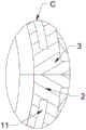
fig. 7 is an enlarged view of the position C of the present invention.
Reference numbers in the figures: 1. a base; 2. a lower housing; 3. an upper housing; 4. a mixing mechanism; 41. a rotating shaft; 42. A spiral feed lobe; 43. a sliding sleeve; 44. glue mixing claws; 45. defining an aperture; 46. a first threaded hole; 47. Fixing the bolt; 48. a second pulley; 49. a motor; 410. a first pulley; 411. a belt; 5. A feed inlet; 6. a discharge port; 7. a dust removal mechanism; 71. a support bar; 72. a dust collection cover; 73. a vacuum cleaner; 74. an air tube; 75. a dust collecting box; 76. a door; 8. a locking mechanism; 81. connecting blocks; 82. l-shaped strips; 83. a second threaded hole; 84. a screw; 85. a hand wheel; 86. a locking block; 9. spraying a glue opening; 10. an auxiliary agent filling port; 11. a cooling chamber; 12. a water inlet; 13. a water outlet; 14. and (4) a filter screen.
Detailed Description
The present invention will be further described with reference to the accompanying drawings and embodiments.
In the specific implementation process, as shown in fig. 1, 4 and 6, a high-efficiency ring-type glue mixer capable of applying functional additives comprises a base 1, a lower shell 2 is fixed on the top of the base 1, the top of the lower shell 2 is rotatably connected with an upper shell 3 through a hinge, a mixing mechanism 4 for stirring wood shavings to enable the wood shavings to be fully mixed with glue is arranged on the inner wall of the lower shell 2, a feed port 5 is fixed on one end of the upper shell 3, a discharge port 6 is fixed on one end of the lower shell 2 far away from the feed port 5, a dust removing mechanism 7 for removing dust generated during feeding is fixed on one side of the top of the base 1 close to the feed port 5, a locking mechanism 8 for locking the upper shell 3 and the lower shell 2 is fixed on one side of the lower shell 2, a glue spraying port 9 is fixed on one end of the top of the upper shell 3 close to the feed port 5, an auxiliary agent filling port 10 is fixed at one end of the top of the upper shell 3 close to the glue spraying port 9.
Referring to fig. 2, 4 and 5, the mixing mechanism 4 includes a rotating shaft 41, a spiral feeding blade 42, a sliding sleeve 43, a glue mixing claw 44, a limiting hole 45, a first threaded hole 46, a fixing bolt 47, a second pulley 48, a motor 49, a first pulley 410 and a belt 411, the rotating shaft 41 is rotatably connected to the inner wall of the lower housing 2 through a bearing, the spiral feeding blade 42 is fixed to the outer wall of one end of the rotating shaft 41 close to the feeding hole 5, the sliding sleeve 43 is fixed to the outer wall of one end of the rotating shaft 41 far from the spiral feeding blade 42 at an equal distance, the glue mixing claw 44 is slidably connected to the inner wall of the sliding sleeve 43, the limiting hole 45 is formed in the outer wall of the glue mixing claw 44 at an equal distance, the first threaded hole 46 is formed in one side of the sliding sleeve 43 close to the limiting hole 45, the fixing bolt 47 is connected to the sliding sleeve 43 through the first threaded hole 46, one end of the fixing bolt 47 is sleeved with one, casing 2 is fixed with second belt pulley 48 down is passed to the one end that pivot 41 is close to feed inlet 5, the one end that base 1 upper surface is close to feed inlet 5 is fixed with motor 49, the output of motor 49 is fixed with first belt pulley 410, first belt pulley 410 passes through the belt 411 transmission with second belt pulley 48 and is connected, can the effectual glue mixing work of accomplishing the wood shavings, can conveniently adjust the clearance between glue mixing claw 44 and last casing 3 and lower casing 2 simultaneously.
Referring to fig. 1 and 2, the dust removing mechanism 7 includes a support rod 71, a dust hood 72, a dust collector 73, an air pipe 74, a dust box 75 and a door 76, the support rod 71 is fixed at one end of the top of the base 1 close to the feed port 5, the dust hood 72 is fixed at the top of the two support rods 71, the dust collector 73 is fixed at the top of the base 1, the dust inlet end of the dust collector 73 is communicated with the dust hood 72 through the air pipe 74, the dust box 75 is fixed at the top of the base 1, the dust outlet end of the dust collector 73 is communicated with the dust box 75, the door 76 is rotatably connected to one side of the dust box 75 far from the dust collector 73 through a hinge, and the filter screen 14 is fixed at the middle part of the door 76, so that dust generated when shavings are thrown into the glue mixer can be effectively removed.
Referring to fig. 2 and 3, locking mechanism 8 includes connecting block 81, L type strip 82, second screw hole 83, screw rod 84, hand wheel 85 and latch segment 86, casing 2 is fixed with connecting block 81, two near one side symmetry equidistance of bracing piece 71 down the middle part of connecting block 81 is connected with L type strip 82 through the pivot rotation, second screw hole 83 has been seted up at the top of L type strip 82, L type strip 82 has screw rod 84 through second screw hole 83 threaded connection, the top of screw rod 84 is fixed with hand wheel 85, it is fixed with latch segment 86 near one side equidistance of connecting block 81 to go up casing 3, and screw rod 84 and latch segment 86 cooperate, can effectual closed casing 3 and casing 2 down.
Referring to fig. 1, fig. 6 and fig. 7, cooling chamber 11 has all been seted up to the inside of going up casing 3 and the inside of casing 2 down, the one end that goes up casing 3 and casing 2 and be close to discharge gate 6 all is fixed with water inlet 12, two water inlet 12 is linked together with two cooling chamber 11 respectively, the one end that goes up casing 3 and casing 2 and be close to feed inlet 5 all is fixed with delivery port 13, two delivery port 13 is linked together with two cooling chamber 11 respectively, can effectually cool off last casing 3 and casing 2 under to the during operation, avoids inside glue to solidify because of the friction themogenesis of wood shavings.
The working principle is as follows:
when in use, the wood shaving scraps are added at the feed port 5, the driving motor 49 rotates the first belt pulley 410, the belt 411 is driven to rotate, the second belt pulley 48 rotates, the rotating shaft 41 rotates, the spiral feeding blade 42 rotates, the wood shaving scraps are driven to advance to the discharge port 6, the wood shaving scraps reach the glue spraying port 9, the glue feeding end of the glue spraying port 9 is connected with a glue pouring device, glue is sprayed to the wood shaving scraps through the glue spraying port 9, the auxiliary agent filling port 10 is connected with a functional auxiliary agent pouring device, the functional auxiliary agent is added to the wood shaving scraps through the auxiliary agent filling port 10, the glue mixing claw 44 continuously rotates to drive the wood shaving scraps to be continuously mixed with the glue and the functional auxiliary agent, and the mixed wood shaving scraps are driven to move to the discharge port 6 under the action of the glue mixing claw 44 and then discharged from the discharge port 6, when the wood shavings chips are added from the feeding hole 5, the dust collector 73 is driven, negative pressure is formed at the dust collecting cover 72, so that dust generated by feeding is collected into the dust collecting box 75 through the air pipe 74 under the action of the dust collector 73, meanwhile, when glue is mixed, cooling water is added at the water inlet 12, the cooling water flows to the water outlet 13 in the cooling cavity 11 and flows out, the effect of cooling the upper shell 3 and the lower shell 2 is achieved, the phenomenon that the internal glue is solidified due to friction heating of the wood shavings chips is avoided, when the gap between the glue mixing claw 44 and the inner walls of the upper shell 3 and the lower shell 2 needs to be adjusted, the glue mixing claw 44 moves up and down along the sliding sleeve 43 by loosening the fixing bolt 47, the distance between the glue mixing claw 44 and the inner walls of the upper shell 3 and the lower shell 2 is adjusted, and when the required position is adjusted, the fixing bolt 47 is tightened, so that the fixing bolt 47 abuts against the limiting hole 45, when the glue mixer needs to be opened, the hand wheel 85 is rotated, the screw rod 84 is separated from the second threaded hole 83, the L-shaped strip 82 is rotated to the lower end of the locking block 86, the upper shell 3 is rotated, and the glue mixer is opened.
The above only is the embodiment of the present invention, not limiting the scope of the present invention, all the equivalent structures or equivalent processes of the present invention are used in the specification and the attached drawings, or directly or indirectly applied to other related technical fields, and the same principle is included in the protection scope of the present invention.
Claims (6)
1. The high-efficiency ring-type glue mixer capable of applying functional additives comprises a base (1) and is characterized in that a lower shell (2) is fixed at the top of the base (1), the top of the lower shell (2) is rotatably connected with an upper shell (3) through a hinge, a mixing mechanism (4) used for stirring wood shavings to enable the wood shavings to be fully mixed with glue is arranged on the inner wall of the lower shell (2), a feed inlet (5) is fixed at one end of the upper shell (3), a discharge outlet (6) is fixed at one end, far away from the feed inlet (5), of the lower shell (2), a dust removing mechanism (7) used for removing dust generated during feeding is fixed at one side, close to the feed inlet (5), of the top of the base (1), a locking mechanism (8) used for locking the upper shell (3) and the lower shell (2) is fixed at one side of the lower shell (2), a glue spraying opening (9) is fixed at one end, close to the feed inlet (5), of the top of the, an auxiliary agent filling port (10) is fixed at one end of the top of the upper shell (3) close to the glue spraying port (9).
2. The high-efficiency ring type glue mixer capable of applying functional additives according to claim 1, wherein the mixing mechanism (4) comprises a rotating shaft (41), a spiral feeding blade (42), a sliding sleeve (43), a glue mixing claw (44), a limiting hole (45), a first threaded hole (46), a fixing bolt (47), a second pulley (48), a motor (49), a first pulley (410) and a belt (411), the inner wall of the lower shell (2) is rotatably connected with the rotating shaft (41) through a bearing, the outer wall of one end of the rotating shaft (41) close to the feeding port (5) is fixed with the spiral feeding blade (42), the outer wall of one end of the rotating shaft (41) far away from the spiral feeding blade (42) is equidistantly fixed with the sliding sleeve (43), the inner wall of the sliding sleeve (43) is slidably connected with the glue mixing claw (44), the outer wall of the glue mixing claw (44) is provided with the limiting hole (45), first screw hole (46) have been seted up to one side that sliding sleeve (43) are close to limited hole (45), sliding sleeve (43) have fixing bolt (47) through first screw hole (46) threaded connection, one end and glue mixing claw (44) of fixing bolt (47) are injectd hole (45) and are cup jointed, casing (2) are fixed with second belt pulley (48) down passed in the one end that pivot (41) are close to feed inlet (5), the one end that base (1) upper surface is close to feed inlet (5) is fixed with motor (49), the output of motor (49) is fixed with first belt pulley (410), first belt pulley (410) pass through belt (411) transmission with second belt pulley (48) and are connected.
3. The high-efficiency ring type glue mixer capable of applying functional additives according to claim 1, is characterized in that, the dust removing mechanism (7) comprises a support rod (71), a dust collecting cover (72), a dust collector (73), an air pipe (74), a dust collecting box (75) and a door (76), one end of the top of the base (1) close to the feed inlet (5) is fixed with a support rod (71), the tops of the two support rods (71) are fixed with a dust collection cover (72), a dust collector (73) is fixed at the top of the base (1), the dust inlet end of the dust collector (73) is communicated with a dust collection cover (72) through an air pipe (74), a dust collecting box (75) is fixed at the top of the base (1), the dust outlet end of the dust collector (73) is communicated with the dust collecting box (75), the side of the dust collection box (75) far away from the dust collector (73) is rotatably connected with a door (76) through a hinge.
4. The high-efficiency ring type glue mixer capable of applying functional additives according to claim 3, is characterized in that, the locking mechanism (8) comprises a connecting block (81), an L-shaped strip (82), a second threaded hole (83), a screw rod (84), a hand wheel (85) and a locking block (86), connecting blocks (81) are symmetrically and equidistantly fixed on one side of the lower shell (2) close to the supporting rod (71), the middle parts of the two connecting blocks (81) are rotationally connected with L-shaped strips (82) through shaft pins, a second threaded hole (83) is formed in the top of the L-shaped strip (82), the L-shaped strip (82) is in threaded connection with a screw rod (84) through the second threaded hole (83), the top of screw rod (84) is fixed with hand wheel (85), one side equidistance that goes up casing (3) and be close to connecting block (81) is fixed with latch segment (86), and screw rod (84) and latch segment (86) cooperate.
5. The high-efficiency ring type glue mixer capable of applying functional additives according to claim 1, wherein cooling cavities (11) are formed in the upper casing (3) and the lower casing (2), water inlets (12) are fixed at the ends of the upper casing (3) and the lower casing (2) close to the discharge hole (6), the two water inlets (12) are respectively communicated with the two cooling cavities (11), water outlets (13) are fixed at the ends of the upper casing (3) and the lower casing (2) close to the feed hole (5), and the two water outlets (13) are respectively communicated with the two cooling cavities (11).
6. The high-efficiency ring type glue mixer capable of applying functional additives is characterized in that a filter screen (14) is fixed in the middle of the door (76).
Priority Applications (1)
| Application Number | Priority Date | Filing Date | Title |
|---|---|---|---|
| CN202022256130.5U CN213643777U (en) | 2020-10-12 | 2020-10-12 | Can apply high efficiency ring type glue mixer of functional additive |
Applications Claiming Priority (1)
| Application Number | Priority Date | Filing Date | Title |
|---|---|---|---|
| CN202022256130.5U CN213643777U (en) | 2020-10-12 | 2020-10-12 | Can apply high efficiency ring type glue mixer of functional additive |
Publications (1)
| Publication Number | Publication Date |
|---|---|
| CN213643777U true CN213643777U (en) | 2021-07-09 |
Family
ID=76700403
Family Applications (1)
| Application Number | Title | Priority Date | Filing Date |
|---|---|---|---|
| CN202022256130.5U Active CN213643777U (en) | 2020-10-12 | 2020-10-12 | Can apply high efficiency ring type glue mixer of functional additive |
Country Status (1)
| Country | Link |
|---|---|
| CN (1) | CN213643777U (en) |
-
2020
- 2020-10-12 CN CN202022256130.5U patent/CN213643777U/en active Active
Similar Documents
| Publication | Publication Date | Title |
|---|---|---|
| CN210473880U (en) | Powder chemical raw material blanking device | |
| CN105563681B (en) | Fast disassembly type mixer | |
| CN209438733U (en) | It is a kind of can be to the industrial chemicals grinding device that dust is collected | |
| CN213643777U (en) | Can apply high efficiency ring type glue mixer of functional additive | |
| CN112611191A (en) | Multifunctional particulate matter drying mechanism | |
| CN115366292B (en) | Batching device for plastic woven bags | |
| CN209850635U (en) | Manual and automatic integrated metallographic cutting machine | |
| CN111282692A (en) | Waste lithium battery treatment device | |
| CN216605162U (en) | Granulator for pig feed processing | |
| CN213645148U (en) | Sand washing device for constructional engineering | |
| CN214442811U (en) | Sand mixer convenient to unload | |
| CN213433953U (en) | A biax paddle mixes machine for lutein pulverization is handled | |
| CN212205440U (en) | Chemical product drying device | |
| CN209631074U (en) | A kind of oil-free piston type air compressor piston composite material mixing arrangement | |
| CN213434203U (en) | Battery positive electrode dry mixing equipment | |
| CN218965048U (en) | Simple polishing equipment | |
| CN219463300U (en) | Batch paint mixing kettle | |
| CN220919538U (en) | Slag powder winnowing machine with anti-blocking function | |
| CN216159583U (en) | Superfine silica flour drying equipment | |
| CN216224127U (en) | Double-shaft prepressing screw machine | |
| CN214218930U (en) | Accurate feeding device of multi-bin cotton mixing machine | |
| CN213475620U (en) | Waste slurry treatment device for aerated concrete block production | |
| CN216400169U (en) | Novel internal mixer | |
| CN219788797U (en) | Horizontal concrete mixer | |
| CN209828769U (en) | Blendor convenient to clean jar side wall |
Legal Events
| Date | Code | Title | Description |
|---|---|---|---|
| GR01 | Patent grant | ||
| GR01 | Patent grant |