CN115366292B - Batching device for plastic woven bags - Google Patents
Batching device for plastic woven bags Download PDFInfo
- Publication number
- CN115366292B CN115366292B CN202211309111.1A CN202211309111A CN115366292B CN 115366292 B CN115366292 B CN 115366292B CN 202211309111 A CN202211309111 A CN 202211309111A CN 115366292 B CN115366292 B CN 115366292B
- Authority
- CN
- China
- Prior art keywords
- crushing roller
- rotating shaft
- main
- side wall
- mixing
- Prior art date
- Legal status (The legal status is an assumption and is not a legal conclusion. Google has not performed a legal analysis and makes no representation as to the accuracy of the status listed.)
- Active
Links
Images


Classifications
-
- B—PERFORMING OPERATIONS; TRANSPORTING
- B29—WORKING OF PLASTICS; WORKING OF SUBSTANCES IN A PLASTIC STATE IN GENERAL
- B29B—PREPARATION OR PRETREATMENT OF THE MATERIAL TO BE SHAPED; MAKING GRANULES OR PREFORMS; RECOVERY OF PLASTICS OR OTHER CONSTITUENTS OF WASTE MATERIAL CONTAINING PLASTICS
- B29B13/00—Conditioning or physical treatment of the material to be shaped
- B29B13/10—Conditioning or physical treatment of the material to be shaped by grinding, e.g. by triturating; by sieving; by filtering
-
- B—PERFORMING OPERATIONS; TRANSPORTING
- B29—WORKING OF PLASTICS; WORKING OF SUBSTANCES IN A PLASTIC STATE IN GENERAL
- B29B—PREPARATION OR PRETREATMENT OF THE MATERIAL TO BE SHAPED; MAKING GRANULES OR PREFORMS; RECOVERY OF PLASTICS OR OTHER CONSTITUENTS OF WASTE MATERIAL CONTAINING PLASTICS
- B29B13/00—Conditioning or physical treatment of the material to be shaped
- B29B13/06—Conditioning or physical treatment of the material to be shaped by drying
- B29B13/065—Conditioning or physical treatment of the material to be shaped by drying of powder or pellets
-
- B—PERFORMING OPERATIONS; TRANSPORTING
- B29—WORKING OF PLASTICS; WORKING OF SUBSTANCES IN A PLASTIC STATE IN GENERAL
- B29B—PREPARATION OR PRETREATMENT OF THE MATERIAL TO BE SHAPED; MAKING GRANULES OR PREFORMS; RECOVERY OF PLASTICS OR OTHER CONSTITUENTS OF WASTE MATERIAL CONTAINING PLASTICS
- B29B7/00—Mixing; Kneading
- B29B7/02—Mixing; Kneading non-continuous, with mechanical mixing or kneading devices, i.e. batch type
- B29B7/06—Mixing; Kneading non-continuous, with mechanical mixing or kneading devices, i.e. batch type with movable mixing or kneading devices
- B29B7/10—Mixing; Kneading non-continuous, with mechanical mixing or kneading devices, i.e. batch type with movable mixing or kneading devices rotary
- B29B7/18—Mixing; Kneading non-continuous, with mechanical mixing or kneading devices, i.e. batch type with movable mixing or kneading devices rotary with more than one shaft
-
- Y—GENERAL TAGGING OF NEW TECHNOLOGICAL DEVELOPMENTS; GENERAL TAGGING OF CROSS-SECTIONAL TECHNOLOGIES SPANNING OVER SEVERAL SECTIONS OF THE IPC; TECHNICAL SUBJECTS COVERED BY FORMER USPC CROSS-REFERENCE ART COLLECTIONS [XRACs] AND DIGESTS
- Y02—TECHNOLOGIES OR APPLICATIONS FOR MITIGATION OR ADAPTATION AGAINST CLIMATE CHANGE
- Y02W—CLIMATE CHANGE MITIGATION TECHNOLOGIES RELATED TO WASTEWATER TREATMENT OR WASTE MANAGEMENT
- Y02W30/00—Technologies for solid waste management
- Y02W30/50—Reuse, recycling or recovery technologies
- Y02W30/52—Mechanical processing of waste for the recovery of materials, e.g. crushing, shredding, separation or disassembly
-
- Y—GENERAL TAGGING OF NEW TECHNOLOGICAL DEVELOPMENTS; GENERAL TAGGING OF CROSS-SECTIONAL TECHNOLOGIES SPANNING OVER SEVERAL SECTIONS OF THE IPC; TECHNICAL SUBJECTS COVERED BY FORMER USPC CROSS-REFERENCE ART COLLECTIONS [XRACs] AND DIGESTS
- Y02—TECHNOLOGIES OR APPLICATIONS FOR MITIGATION OR ADAPTATION AGAINST CLIMATE CHANGE
- Y02W—CLIMATE CHANGE MITIGATION TECHNOLOGIES RELATED TO WASTEWATER TREATMENT OR WASTE MANAGEMENT
- Y02W30/00—Technologies for solid waste management
- Y02W30/50—Reuse, recycling or recovery technologies
- Y02W30/62—Plastics recycling; Rubber recycling
Abstract
The invention provides a batching device of a plastic woven bag, which belongs to the technical field of plastic woven bags and comprises a batching mechanism and a mixing device, wherein the batching mechanism is communicated with the mixing device, the bottom of the mixing device is provided with a material conveying pipe, a fixed frame is fixedly arranged inside the batching mechanism, a movable rotating ring is rotatably connected inside the batching mechanism through a bearing, and a fixed bin is fixedly arranged at the central bottom of the fixed frame. The device can perform crushing work of gradually reducing particles on production raw materials, improves the crushing effect and the crushing efficiency through multi-stage crushing, simultaneously has high-efficiency dehumidification and moisture removal effects on the crushed raw materials through heating of the electric heating net and hot air sprayed by the air nozzle, can prevent the raw materials from being condensed and adhered inside the device due to overhigh humidity, ensures that the dried materials are more easily crushed and mixed, and further can improve the production quality of polypropylene plastic woven bags.
Description
Technical Field
The invention relates to the field of plastic woven bags, in particular to a batching device of a plastic woven bag.
Background
Woven bags are also known as snakeskin bags. Is one kind of plastic bag for packing and is produced with polyethylene, polypropylene and other plastic material. When the plastic woven sack is produced, need use dosing unit to mix the stirring to the chemical plastics raw materials.
The prior art publication number is CN216458515U discloses a dosing unit for producing plastic woven sack, the on-line screen storage device comprises a base, the top fixedly connected with support column of base, the top fixedly connected with spring of support column, the top fixedly connected with connecting block of spring, the top fixedly connected with backup pad of connecting block, the top fixedly connected with batching box of backup pad, the lower fixed surface of backup pad is connected with vibrating motor, the interior roof fixedly connected with bottom annular slide rail of batching box. The publication has the following advantages and effects: through setting up support column, spring, connecting block, backup pad, batching box, vibrating motor, bottom annular slide rail, head rod, scraper blade, second connecting rod, handle and top annular slide rail, this design can effectively avoid the plastics raw materials to adhere to on the batching box inner wall, and the discharge is thorough when making the batching box arrange the material, avoids appearing the waste of plastics raw materials.
However, the prior art still has certain limitations, the plastic woven bag is heated and drawn after raw materials are required to be mixed with various additives in the manufacturing process, but because the raw materials are large in volume and large in quantity, the raw materials are difficult to be thoroughly mixed by direct adding and stirring, and large raw material particles or lumps sometimes exist in the raw materials, so that the large particles and the lumps not only influence the sufficient contact reaction of the raw materials and the additives, but also slow heating and melting speed in the subsequent heating and drawing process, and further influence the overall production quality of the plastic woven bag.
How to invent a batching device for plastic woven bags to improve the problems becomes a problem to be solved urgently by the technical personnel in the field.
Disclosure of Invention
In order to make up for the defects, the invention provides a batching device for a plastic woven bag, and aims to solve the problems that in the prior art, an additive is low in mixing efficiency and raw materials are easy to agglomerate.
The invention is realized by the following steps:
the invention provides a batching device of a plastic woven bag, which comprises a batching mechanism and a mixing device, wherein the batching mechanism is communicated with the mixing device, the bottom of the mixing device is provided with a material conveying pipe, the inside of the batching mechanism is fixedly provided with a fixed frame, the inside of the batching mechanism is rotatably connected with a movable rotating ring through a bearing, the central bottom of the fixed frame is fixedly provided with a fixed bin, the inside of the material conveying pipe is fixedly provided with a driving motor through a group of fixed rods, the inside of the mixing device is provided with a main crushing and mixing mechanism, the main crushing and mixing mechanism comprises a main driving rotating shaft, one end of the main driving rotating shaft is fixedly connected with an output shaft of the driving motor, the other end of the main driving rotating shaft penetrates through the fixed bin and is rotatably connected with the fixed frame, the outer side wall of the main driving rotating shaft is fixedly provided with a main upper crushing roller and a main lower crushing roller, the diameter of the main upper crushing roller is larger than that of the main crushing and mixing mechanism, the main crushing roller and the main crushing and mixing mechanism are connected through a group of conical inclined planes, and a plurality of secondary crushing and mixing mechanisms which are distributed annularly are arranged inside the mixing device;
the secondary crushing and mixing mechanism comprises a secondary driving rotating shaft, two ends of the secondary driving rotating shaft are rotatably connected with the interior of the mixing device through bearings, a first lower crushing roller and a secondary upper crushing roller are fixedly mounted on the outer side wall of the secondary driving rotating shaft, the diameter of the secondary upper crushing roller is larger than that of the first lower crushing roller, the secondary upper crushing roller and the first lower crushing roller are connected through a group of conical inclined planes, a plurality of groups of annularly distributed guide vanes are further fixedly mounted on the conical inclined planes, the primary upper crushing roller is close to the secondary upper crushing roller, the primary lower crushing roller is close to the first lower crushing roller, and the guide vanes are attached to the conical inclined planes of the primary crushing and mixing mechanism;
through the above scheme, utilize the cooperation between secondary broken mixing mechanism and the main broken mixing mechanism, can carry out multistage breakage and mixed effect to plastic woven sack production raw and other materials, can make the raw material piece of conglomeration scatter and to the breakage of large granule raw and other materials, can show area of contact and the mixed effect between promotion raw and other materials and the additive, the raw materials in small, broken bits and external area of contact are bigger moreover, be convenient for follow-up heating wire drawing production plastic woven sack to the raw materials, can improve the efficiency and the quality of follow-up processing flow.
Preferably, a group of filling crushing rollers close to the main-stage upper crushing roller and the main-stage lower crushing roller are arranged between the adjacent two groups of first lower crushing rollers and the main-stage lower crushing roller, and the filling crushing rollers are fixedly connected with the inner part of the mixing device.
Preferably, the top of the batching mechanism is provided with a feeding hole, the position of the crushing roller on the main stage is opposite to the feeding hole of the batching mechanism, the squeezing roller strip on the side wall of the crushing roller on the main stage is attached to the inner side wall of the mixing device, and a gap exists between the crushing roller on the main stage and the crushing roller on the secondary stage.
Preferably, the bottom of mixing arrangement is provided with the chamfer angle towards the conveying pipeline inboard, and guide vane's edge and mixing arrangement's inboard wall are laminated mutually, and mixing arrangement's inside is provided with the water conservancy diversion baffle, and the water conservancy diversion baffle is laminated mutually with the outside wall of first crushing roller mutually, and the top and the bottom of water conservancy diversion baffle laminate mutually with guide vane and the roll strip of first crushing roller respectively.
Preferably, the gap between the primary upper crushing roller and the secondary upper crushing roller is greater than the gap between the primary lower crushing roller and the first lower crushing roller.
Preferably, the inside of crushing roller is the cavity design on first crushing roller and the secondary, mixing arrangement's inboard bottom fixed mounting has a set of atmospheric pressure box that extends to first crushing roller inside, the activity slider has been cup jointed in the spacing activity in inside of atmospheric pressure box, the surface of first crushing roller is porous filter plate form design, the inside wall fixed mounting of first crushing roller has the electrical heating net, the air nozzle towards electrical heating net direction is seted up to the lateral wall of atmospheric pressure box, the lateral wall fixed mounting of secondary drive pivot has the drive wheel.
Preferably, a driving gear is fixedly mounted on the outer side wall of the secondary driving rotating shaft, a gear ring meshed with the driving gear is arranged on the inner side wall of the movable rotating ring, and the movable rotating ring is fixedly connected with the main driving rotating shaft.
Preferably, the drive wheel is oval design, and the atmospheric pressure box is provided with the arc sunken with drive wheel profile looks adaptation towards the drive wheel direction, and the one side that the activity slider faced the drive wheel is the arc design.
Preferably, a spherical cavity is formed in the fixed bin, a movable rotating shaft is rotatably connected to the inside of the spherical cavity through a bearing, a plurality of groups of annular blades distributed annularly are fixedly mounted on the outer side wall of the movable rotating shaft, the storage bin is formed in the fixed bin, a groove communicated with the spherical cavity is formed in the storage bin, and a groove communicated with the outside of the fixed bin is formed in the bottom of the spherical cavity.
Preferably, the part of the movable rotating shaft, which is close to the main driving rotating shaft, is in transmission connection through two groups of bevel gears which are meshed with each other, the contact part of the movable rotating shaft and the spherical cavity keeps tightness, the edges of the annular blades are in a rounded design, and the edges of the annular blades are attached to the inner side wall of the spherical cavity.
The invention has the beneficial effects that:
1. through the clearance between secondary broken mixing mechanism and the main broken mixing mechanism diminishing from the top down gradually, can carry out the crushing work that the granule diminishes gradually to production raw and other materials, through multistage breakage, crushing effect and crushing efficiency have been improved, can make the raw material piece of reunion scatter and to the breakage of large granule raw and other materials, can show the contact area and the mixed effect that promote between raw and other materials and the additive, meanwhile, heating and air nozzle spun steam through electric heating net can play high-efficient dehumidification effect to the raw materials after preliminary breakage, not only can prevent that raw and other materials humidity from excessively condensing and adhesion inside the device, and the material after the drying is changeed breakage and mixes, and dehydration also can reduce the influence of moisture to the proportion of raw and other materials, further can improve the quality of polypropylene plastic woven sack production.
2. Can drive the annular blade and rotate and continuously add the additive quantitatively through main broken mixing mechanism pivoted in time, make additive and raw and other materials wholly combine more evenly through the mode that continuously quantitatively adds, avoid the additive to appear locally piling up and deposit to promote the quality of follow-up raw and other materials production polypropylene plastic woven sack.
Drawings
In order to more clearly illustrate the technical solutions of the embodiments of the present invention, the drawings that are required to be used in the embodiments will be briefly described below, it should be understood that the following drawings only illustrate some embodiments of the present invention and therefore should not be considered as limiting the scope, and that those skilled in the art can also obtain other related drawings based on the drawings without inventive efforts.
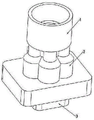
FIG. 1 is a schematic view of the overall external structure of a batching device for plastic woven bags according to an embodiment of the present invention;
FIG. 2 is a schematic view of the overall internal structure of a batching device for plastic woven bags according to an embodiment of the present invention;
FIG. 3 is a schematic view of an internal cross-sectional structure of a batching device for plastic woven bags according to an embodiment of the present invention;
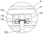
FIG. 4 is an enlarged schematic view taken at A of FIG. 3 in accordance with the present invention;
FIG. 5 is a schematic top view of a mixing mechanism of a batching device for plastic woven bags according to an embodiment of the present invention;
FIG. 6 is a schematic view of the internal structure of a mixing mechanism of a batching device for plastic woven bags according to an embodiment of the present invention;
FIG. 7 is a schematic view of an internal structure of a movable rotating ring of a batching device for plastic woven bags according to an embodiment of the present invention;
FIG. 8 is a schematic view of the internal working conditions of the secondary crushing and mixing mechanism of the batching device for the plastic woven bags according to the embodiment of the invention;
fig. 9 is a schematic view of the rotation condition of the ring-shaped blade of the batching device for the plastic woven bags according to the embodiment of the invention.
In the figure: 1. a batching mechanism; 2. a mixing device; 3. a delivery pipe; 11. a fixed frame; 12. a movable swivel; 21. a secondary crushing and mixing mechanism; 22. a main crushing and mixing mechanism; 23. filling the crushing roller; 24. a flow guide baffle plate; 31. a drive motor; 111. fixing the bin; 112. a storage bin; 113. an annular blade; 114. a movable rotating shaft; 211. a first lower crushing roller; 212. a secondary upper crushing roller; 213. a guide vane; 214. a secondary drive shaft; 215. a drive wheel; 216. an electrical heating grid; 217. an air pressure box; 218. a movable slide block; 219. an air nozzle; 220. a drive gear; 221. a primary upper crushing roller; 222. a primary lower crushing roller; 223. the main drive shaft.
Detailed Description
In order to make the objects, technical solutions and advantages of the embodiments of the present invention more apparent, the technical solutions of the embodiments of the present invention will be described clearly and completely with reference to the accompanying drawings of the embodiments of the present invention, and it is obvious that the described embodiments are some, but not all embodiments of the present invention. All other embodiments, which can be obtained by a person skilled in the art without any inventive step based on the embodiments of the present invention, are within the scope of the present invention.
Examples
Referring to fig. 1-9, a batching device for a plastic woven bag, includes a batching mechanism 1 and a mixing device 2, the batching mechanism 1 is communicated with the mixing device 2, a feed delivery pipe 3 is disposed at the bottom of the mixing device 2, a fixed frame 11 is fixedly disposed inside the batching mechanism 1, a movable swivel 12 is rotatably connected inside the batching mechanism 1 through a bearing, a fixed bin 111 is fixedly disposed at the central bottom of the fixed frame 11, a driving motor 31 is fixedly disposed inside the feed delivery pipe 3 through a set of fixed rods, a main crushing and mixing mechanism 22 is disposed inside the mixing device 2, the main crushing and mixing mechanism 22 includes a main driving rotating shaft 223, one end of the main driving rotating shaft 223 is fixedly connected with an output shaft of the driving motor 31, the other end of the main driving rotating shaft 223 penetrates through the fixed bin 111 and is rotatably connected with the fixed frame 11, a main upper crushing roller 221 and a main lower crushing roller 222 are fixedly disposed on an outer side wall of the main driving rotating shaft 223, a diameter of the main upper crushing roller 221 is larger than a diameter of the main crushing and mixing mechanism 22, and the main upper crushing roller 221 is connected with the main crushing and mixing mechanism 22 through a set of tapered inclined planes, and a plurality of sets of secondary crushing mechanisms 21 are disposed inside the mixing device 2;
the secondary crushing and mixing mechanism 21 comprises a secondary driving rotating shaft 214, two ends of the secondary driving rotating shaft 214 are rotatably connected with the interior of the mixing device 2 through bearings, a first lower crushing roller 211 and a secondary upper crushing roller 212 are fixedly installed on the outer side wall of the secondary driving rotating shaft 214, the diameter of the secondary upper crushing roller 212 is larger than that of the first lower crushing roller 211, the secondary upper crushing roller 212 is connected with the first lower crushing roller 211 through a group of conical inclined surfaces, a plurality of groups of guide vanes 213 which are distributed annularly are also fixedly installed on the conical inclined surfaces, the main upper crushing roller 221 is close to the secondary upper crushing roller 212, the main lower crushing roller 222 is close to the first lower crushing roller 211, and the guide vanes 213 are attached to the conical inclined surfaces of the main crushing and mixing mechanism 22;
it should be noted that the material conveying pipe 3 is communicated with the inlet of the plastic wire drawing machine, and the processed raw materials can be woven into a plastic woven bag by a weaving machine after entering the plastic wire drawing machine for heating and wire drawing.
Referring to fig. 3, a set of filling crushing rollers 23 close to the main-stage upper crushing roller 221 and the main-stage lower crushing roller 222 is provided between two adjacent sets of the first lower crushing rollers 211 and the main-stage lower crushing roller 222, and the filling crushing rollers 23 are fixedly connected to the inside of the mixing device 2;
it should be noted that the gap between the main lower crushing roller 222 and the first lower crushing roller 211 can be filled by the design of the filling crushing roller 23, and the raw material can be crushed and rotationally agitated and mixed by the relative rotation between the main lower crushing roller 222 and the first lower crushing roller 211 and the filling crushing roller 23 when the raw material flows into the gap due to the fixed design of the filling crushing roller 23.
Further, referring to fig. 5, a feed opening is provided at the top of the batching mechanism 1, the primary upper crushing roller 221 is positioned opposite to the feed opening of the batching mechanism 1, the squeeze roller strip of the side wall of the primary upper crushing roller 221 is fitted to the inner side wall of the mixing device 2, and a gap is provided between the primary upper crushing roller 221 and the secondary upper crushing roller 212.
Referring to fig. 6, the bottom of the mixing device 2 is provided with a chamfer angle facing the inner side of the feed delivery pipe 3, the edge of the guide vane 213 is attached to the inner side wall of the mixing device 2, the inside of the mixing device 2 is provided with a guide baffle 24, the guide baffle 24 is attached to the outer side wall of the first lower crushing roller 211, and the top and the bottom of the guide baffle 24 are respectively attached to the guide vane 213 and the roller strip of the first lower crushing roller 211;
it should be noted that when the guide vane 213 rotates, the mixture contained in the gap between the guide vane 213 and the inner side wall of the mixing device 2 is prevented from entering between the first lower crushing roller 211 and the inner side wall of the mixing device 2 due to the presence of the guide baffle 24, and when the guide vane 213 rotates to the side close to the adjacent first lower crushing roller 211 and the main-stage lower crushing roller 222 or the filling crushing roller 23, the mixed material contained in the inside of the secondary crushing and mixing mechanism 21 flows out.
Further, the gap between the primary upper crushing roller 221 and the secondary upper crushing roller 212 is greater than the gap between the primary lower crushing roller 222 and the first lower crushing roller 211.
Referring to fig. 8, the first lower crushing roller 211 and the secondary upper crushing roller 212 are hollow, a group of air pressure boxes 217 extending into the first lower crushing roller 211 is fixedly installed at the bottom of the inner side of the mixing device 2, a movable slider 218 is movably sleeved in the air pressure boxes 217 in a limiting manner, the surface of the first lower crushing roller 211 is in a porous filter plate shape, an electric heating net 216 is fixedly installed on the inner side wall of the first lower crushing roller 211, an air nozzle 219 facing the electric heating net 216 is arranged on the side wall of the air pressure boxes 217, and a driving wheel 215 is fixedly installed on the outer side wall of the secondary driving rotating shaft 214;
it should be noted that the air nozzle 219 is disposed toward the main crushing and mixing mechanism 22, a spring set is disposed between the movable slider 218 and the inside of the air pressure box 217, the movable slider 218 pushes the spring to compress air to be ejected through the air nozzle 219, when the long axis of the driving wheel 215 is not in contact with the movable slider 218, the movable slider 218 is reset under the elastic force of the spring set, and the external air flows into the inside of the air pressure box 217 through the air nozzle 219.
Referring to fig. 7, a driving gear 220 is fixedly mounted on an outer side wall of the secondary driving rotating shaft 214, a gear ring meshed with the driving gear 220 is disposed on an inner side wall of the movable rotating ring 12, and the movable rotating ring 12 is fixedly connected with the main driving rotating shaft 223;
it should be noted that, since the number of teeth of the inner gear ring of the movable rotating ring 12 is much larger than that of the driving gear 220, when the movable rotating ring 12 and the main crushing and mixing mechanism 22 rotate at the same speed, the rotating speed of the secondary crushing and mixing mechanism 21 is different from that of the main crushing and mixing mechanism 22.
Further, the driving wheel 215 is designed in an oval shape, the air pressure box 217 is provided with an arc-shaped recess matched with the rotating profile of the driving wheel 215 towards the driving wheel 215, and one side of the movable slider 218 facing the driving wheel 215 is designed in an arc shape.
As shown in fig. 4, a spherical cavity is opened inside the fixed bin 111, the inside of the spherical cavity is rotatably connected with a movable rotating shaft 114 through a bearing, a plurality of groups of annular blades 113 distributed annularly are fixedly mounted on the outer side wall of the movable rotating shaft 114, the storage bin 112 is opened inside the fixed bin 111, a groove communicated with the spherical cavity is opened inside the storage bin 112, and a groove communicated with the outside of the fixed bin 111 is opened at the bottom of the spherical cavity.
Furthermore, the adjacent parts of the movable rotating shaft 114 and the main driving rotating shaft 223 are in transmission connection through two groups of bevel gears which are meshed with each other, the contact part of the movable rotating shaft 114 and the spherical cavity keeps tightness, the edges of the annular blades 113 are in a rounded design, and the edges of the annular blades 113 are attached to the inner side wall of the spherical cavity.
The working principle of the batching device for the plastic woven bag is as follows:
first, the driving motor 31 and the electric heating wire inside the electric heating net 216 are powered on and started, then the main manufacturing raw materials of the polypropylene plastic woven bag such as polyvinyl chloride, molybdenum disulfide, calcium carbonate, carbon black, light stabilizer, tackifier, zinc stearate and the like are added through the opening of the batching mechanism 1, when the raw material mixture enters the mixing device 2 through the opening of the batching mechanism 1, referring to fig. 5, the gap between the crushing roller of the first lower crushing roller 211 and the inner side wall of the mixing device 2 is small, and the gap between the first lower crushing roller 211 and the secondary upper crushing roller 212 is large, so that the mixture flows into the gap between the primary upper crushing roller 221 and the secondary upper crushing roller 212 through the inclined plane at the top of the primary upper crushing roller 221;
when the driving motor 31 is powered on, the driving motor can drive the main driving rotating shaft 223 to rotate, so as to drive the main upper crushing roller 221 and the main lower crushing roller 222 to rotate, and simultaneously drive the movable rotating ring 12 to rotate, and when the movable rotating ring 12 rotates, the driving gear 220 and the secondary driving rotating shaft 214 can be driven to rotate by the gear ring on the inner side wall of the movable rotating ring 12, so as to drive the secondary upper crushing roller 212, the first lower crushing roller 211 and the guide vanes 213 to rotate;
when the mixture flows through the gap between the secondary upper crushing roller 212 and the primary upper crushing roller 221, because the rotating speeds of the secondary upper crushing roller 212 and the primary upper crushing roller 221 are different, the rotation of the secondary upper crushing roller 212 and the primary upper crushing roller 221 can roll and crush the mixture in the gap between the primary upper crushing roller 221 and the secondary upper crushing roller 212, the caking of the raw material mixture can be crushed, meanwhile, certain stirring and mixing effects can be achieved on the raw material along with the rotation of the secondary upper crushing roller 212 and the primary upper crushing roller 221, so that the raw materials are uniformly mixed, and the quality of producing the polypropylene plastic woven bag by subsequent heating extrusion is improved;
when the main driving rotating shaft 223 rotates, the bevel gear drives the movable rotating shaft 114 to rotate, so as to drive the annular blade 113 to rotate, referring to fig. 9, when the annular blade 113 is stationary, the additive inside the storage bin 112 can be prevented from flowing out through the spherical cavity and the annular blade 113, when the annular blade 113 rotates, the additive inside the storage bin 112 can flow out through the rotation of the annular blade 113, and is mixed with the raw material mixture inside the mixing device 2, and the additive can be mixed with the raw material mixture through the mixing and stirring of the secondary upper crushing roller 212 and the primary upper crushing roller 221, so that the mixing effect of the raw material and the additive can be improved, the additive and the raw material are integrally combined more uniformly through the continuous quantitative addition of the rotation of the annular blade 113, and the additive is prevented from being locally accumulated and precipitated, so that the quality of the subsequent raw material for producing the polypropylene plastic woven bag is improved;
it should be noted that the used additives include a toughening agent, an antioxidant, a coupling agent, UV-327, etc., which is a prior art for manufacturing polypropylene plastic woven bags, and specifically refer to a polypropylene plastic woven bag disclosed in publication No. CN202210810081.6 and a production method thereof;
when the primarily crushed and mixed raw materials continuously flow downwards, the raw materials flow to the gap of the guide vane 213, the raw materials in the gap of the guide vane 213 can be driven to rotate and mix through the rotation of the guide vane 213, a certain stirring and mixing effect can be achieved, the primarily crushed raw materials can be further mixed and stirred, because the gap between the first lower crushing roller 211 and the main lower crushing roller 222 is smaller than the gap between the main upper crushing roller 221 and the secondary upper crushing roller 212, the gap between the secondary crushing and mixing mechanism 21 and the main crushing and mixing mechanism 22 is gradually reduced from top to bottom, the crushing work of gradually reducing particles can be performed on the raw materials for production, through multi-stage crushing, the crushing effect and the crushing efficiency are improved, agglomerated raw material blocks can be dispersed and large raw materials can be crushed, the contact area and the mixing effect between the raw materials and additives can be remarkably improved, the contact area between the finely crushed raw materials and the outside is larger, the raw materials can be conveniently heated and drawn to produce plastic woven bags, and the efficiency and the quality of subsequent processing flows can be improved;
when the secondary crushing and mixing mechanism 21 rotates, referring to fig. 8, when the first lower crushing roller 211 rotates, the temperature of the first lower crushing roller 211 can be raised by heating the electric heating net 216, a certain heating and water removing effect is achieved on the contacted raw materials which are subjected to primary crushing, and when the secondary driving rotating shaft 214 rotates to the long shaft end of the driving wheel 215 to rotate to pass through the movable slider 218, the movable slider 218 can be pushed to compress the air inside the air pressure box 217, the air is sprayed out through the air nozzle 219, hot air can be sprayed out towards the inside of the mixing device 2 through the filter holes on the surface of the first lower crushing roller 211 along with the heating of the electric heating net 216, the high-efficiency heating and moisture removing effect can be achieved on the crushed mixture, compared with direct heating, the contact area of the crushed materials is larger, the heating effect is better, the efficiency of removing moisture in the raw materials is higher, the raw materials can be prevented from being condensed, the crushing and mixing effect on the raw materials can be improved, and the influence of the moisture on the proportion of the raw materials can be reduced by the dehydration treatment, and the production quality of the polypropylene plastic woven bag can be further improved.
It should be noted that the specific model specification of the motor needs to be determined by type selection according to the actual specification of the device, and the specific type selection calculation method adopts the prior art in the field, so detailed description is omitted.
The above description is only a preferred embodiment of the present invention, and is not intended to limit the present invention, and various modifications and changes may be made to the present invention by those skilled in the art. Any modification, equivalent replacement, or improvement made within the spirit and principle of the present invention should be included in the protection scope of the present invention.
Claims (7)
1. The utility model provides a dosing unit of plastic woven sack, its characterized in that, includes dosing mechanism (1) and mixing arrangement (2), dosing mechanism (1) and mixing arrangement (2) are linked together, the bottom of mixing arrangement (2) is provided with conveying pipeline (3), the inside fixed mounting of dosing mechanism (1) has fixed frame (11), the inside of dosing mechanism (1) rotates through the bearing and is connected with movable swivel (12), the center bottom fixed mounting of fixed frame (11) has fixed storehouse (111), the inside of conveying pipeline (3) has driving motor (31) through a set of dead lever fixed mounting, the inside of mixing arrangement (2) is provided with main broken hybrid mechanism (22), main broken hybrid mechanism (22) includes main drive pivot (223), the one end of main drive pivot (223) and the output shaft fixed connection of driving motor (31), the other end of main drive pivot (223) runs through fixed storehouse (111) and rotates with fixed frame (11) and is connected, the lateral wall fixed mounting of main drive pivot (223) has main upper and lower level crushing roller (221) and a set of main drive roll diameter on the crushing roller (221) and is greater than a set of crushing roller (22) and mixing mechanism (22) diameter on the main drive pivot (223), a plurality of groups of secondary crushing and mixing mechanisms (21) which are distributed annularly are arranged in the mixing device (2);
the secondary crushing and mixing mechanism (21) comprises a secondary driving rotating shaft (214), two ends of the secondary driving rotating shaft (214) are rotatably connected with the interior of the mixing device (2) through bearings, a first lower crushing roller (211) and a secondary upper crushing roller (212) are fixedly installed on the outer side wall of the secondary driving rotating shaft (214), the diameter of the secondary upper crushing roller (212) is larger than that of the first lower crushing roller (211), the secondary upper crushing roller (212) is connected with the first lower crushing roller (211) through a group of conical inclined surfaces, a plurality of groups of guide vanes (213) distributed in an annular mode are fixedly installed on the conical inclined surfaces, the main upper crushing roller (221) is close to the secondary upper crushing roller (212), the main lower crushing roller (222) is close to the first lower crushing roller (211), and the guide vanes (213) are attached to the conical inclined surfaces of the main crushing and mixing mechanism (22);
the inner parts of the first lower crushing roller (211) and the secondary upper crushing roller (212) are designed to be hollow, a group of air pressure boxes (217) extending to the inner part of the first lower crushing roller (211) is fixedly installed at the bottom of the inner side of the mixing device (2), movable sliding blocks (218) are movably sleeved in the air pressure boxes (217) in a limiting mode, the surface of the first lower crushing roller (211) is designed to be in a porous filter plate shape, an electric heating net (216) is fixedly installed on the inner side wall of the first lower crushing roller (211), air nozzles (219) facing to the direction of the electric heating net (216) are formed in the side wall of each air pressure box (217), and a driving wheel (215) is fixedly installed on the outer side wall of the secondary driving rotating shaft (214);
a driving gear (220) is fixedly mounted on the outer side wall of the secondary driving rotating shaft (214), a gear ring meshed with the driving gear (220) is arranged on the inner side wall of the movable rotating ring (12), and the movable rotating ring (12) is fixedly connected with a main driving rotating shaft (223);
the driving wheel (215) is designed in an oval shape, the air pressure box (217) is provided with an arc-shaped recess matched with the rotating profile of the driving wheel (215) towards the driving wheel (215), and one side of the movable sliding block (218) facing the driving wheel (215) is designed in an arc shape.
2. A blending device for plastic woven bags according to claim 1, wherein a set of filling crushing rollers (23) close to the upper primary crushing roller (221) and the lower primary crushing roller (222) is provided between two adjacent sets of the first lower crushing roller (211) and the lower primary crushing roller (222), and the filling crushing rollers (23) are fixedly connected to the inside of the mixing device (2).
3. A dispensing apparatus for plastic woven bags according to claim 1, wherein the top of the dispensing mechanism (1) is provided with a feed inlet, the position of the primary upper crushing roller (221) is opposite to the feed inlet of the dispensing mechanism (1), the extrusion roller strip of the side wall of the primary upper crushing roller (221) is attached to the inner side wall of the mixing device (2), and a gap is present between the primary upper crushing roller (221) and the secondary upper crushing roller (212).
4. The dispensing device for plastic woven bags according to claim 1, wherein the bottom of the mixing device (2) is provided with a chamfer facing the inside of the feed delivery pipe (3), the edge of the guide vane (213) is attached to the inner side wall of the mixing device (2), the inside of the mixing device (2) is provided with a guide baffle (24), the guide baffle (24) is attached to the outer side wall of the first lower crushing roller (211), and the top and bottom of the guide baffle (24) are respectively attached to the guide vane (213) and the roller strip of the first lower crushing roller (211).
5. The blending apparatus of plastic woven bags according to claim 1, wherein the gap between the primary upper crushing roller (221) and the secondary upper crushing roller (212) is larger than the gap between the primary lower crushing roller (222) and the first lower crushing roller (211).
6. The batching device for the plastic woven bags according to claim 1, wherein a spherical cavity is formed inside the fixed bin (111), a movable rotating shaft (114) is rotatably connected inside the spherical cavity through a bearing, a plurality of groups of annular blades (113) which are distributed annularly are fixedly mounted on the outer side wall of the movable rotating shaft (114), a storage bin (112) is formed inside the fixed bin (111), a groove communicated with the spherical cavity is formed inside the storage bin (112), and a groove communicated with the outside of the fixed bin (111) is formed in the bottom of the spherical cavity.
7. The blending device for the plastic woven sack according to the claim 6, characterized in that, the close part of the movable rotating shaft (114) and the main driving rotating shaft (223) is connected through two sets of bevel gears which are meshed with each other, the contact part of the movable rotating shaft (114) and the spherical cavity keeps the sealing performance, the edge of the ring-shaped blade (113) is designed to be rounded, and the edge of the ring-shaped blade (113) is attached to the inner side wall of the spherical cavity.
Priority Applications (1)
| Application Number | Priority Date | Filing Date | Title |
|---|---|---|---|
| CN202211309111.1A CN115366292B (en) | 2022-10-25 | 2022-10-25 | Batching device for plastic woven bags |
Applications Claiming Priority (1)
| Application Number | Priority Date | Filing Date | Title |
|---|---|---|---|
| CN202211309111.1A CN115366292B (en) | 2022-10-25 | 2022-10-25 | Batching device for plastic woven bags |
Publications (2)
| Publication Number | Publication Date |
|---|---|
| CN115366292A CN115366292A (en) | 2022-11-22 |
| CN115366292B true CN115366292B (en) | 2023-01-24 |
Family
ID=84073558
Family Applications (1)
| Application Number | Title | Priority Date | Filing Date |
|---|---|---|---|
| CN202211309111.1A Active CN115366292B (en) | 2022-10-25 | 2022-10-25 | Batching device for plastic woven bags |
Country Status (1)
| Country | Link |
|---|---|
| CN (1) | CN115366292B (en) |
Families Citing this family (1)
| Publication number | Priority date | Publication date | Assignee | Title |
|---|---|---|---|---|
| CN115845684B (en) * | 2023-03-01 | 2023-05-02 | 天津艾尔森生物科技有限公司 | Multifunctional batching device for producing essence |
Citations (2)
| Publication number | Priority date | Publication date | Assignee | Title |
|---|---|---|---|---|
| CN209934823U (en) * | 2019-01-28 | 2020-01-14 | 芜湖博元材料科技有限公司 | Crushing device for atactic polypropylene |
| CN214439395U (en) * | 2020-12-31 | 2021-10-22 | 扬州市开元岩土工程检测有限公司 | Breaker is used in ground reconnaissance |
-
2022
- 2022-10-25 CN CN202211309111.1A patent/CN115366292B/en active Active
Patent Citations (2)
| Publication number | Priority date | Publication date | Assignee | Title |
|---|---|---|---|---|
| CN209934823U (en) * | 2019-01-28 | 2020-01-14 | 芜湖博元材料科技有限公司 | Crushing device for atactic polypropylene |
| CN214439395U (en) * | 2020-12-31 | 2021-10-22 | 扬州市开元岩土工程检测有限公司 | Breaker is used in ground reconnaissance |
Also Published As
| Publication number | Publication date |
|---|---|
| CN115366292A (en) | 2022-11-22 |
Similar Documents
| Publication | Publication Date | Title |
|---|---|---|
| CN107325305A (en) | A kind of filler slurry atomization drying consecutive production equipment | |
| CN115366292B (en) | Batching device for plastic woven bags | |
| CN207825281U (en) | A kind of plastic crushing Double Selection device | |
| CN107962700A (en) | A kind of efficiently PVC is granulated cooling and collects sorting unit | |
| CN207143167U (en) | A kind of filler slurry atomization drying consecutive production equipment | |
| CN110975979A (en) | Powder material discharging device | |
| CN219544119U (en) | Soft water salt preparation is with from mode tablet press equipment | |
| CN216605162U (en) | Granulator for pig feed processing | |
| CN207153513U (en) | A kind of auger equipment | |
| CN105413583B (en) | A kind of efficiently granulator and its method of work | |
| CN209718360U (en) | A kind of chemical fibre recycled polyester proprietary material processing wet crushing mill | |
| CN210436424U (en) | Cut grain device for filling masterbatch production | |
| CN208223121U (en) | A kind of multiple-element long active composite heat transfer dryer | |
| CN208449557U (en) | A kind of squash type material-pulverizing device | |
| CN208068639U (en) | A kind of efficient PVC granulations are cooling to collect sorting unit | |
| CN212942800U (en) | Novel feed granulator | |
| CN210544984U (en) | High-efficient pelletization device | |
| CN209347648U (en) | A kind of swing granule granulator of Chinese medicine | |
| CN215750206U (en) | Preprocessing equipment is used in polymer plastic granules production | |
| CN216321744U (en) | Spiral pushing type carbon graphite particle forming machine | |
| CN220055573U (en) | Anti-blocking device of pneumatic conveying system | |
| CN211964085U (en) | Bamboo wood flour pelletization equipment with novel dust collector | |
| CN213314832U (en) | Prilling granulator is used in compound thoughtlessly fertile production convenient to eliminate peculiar smell | |
| CN219515253U (en) | Rice noodle extruding machine with prevent blockking up | |
| CN219400326U (en) | Plastic granules raw materials breaker |
Legal Events
| Date | Code | Title | Description |
|---|---|---|---|
| PB01 | Publication | ||
| PB01 | Publication | ||
| SE01 | Entry into force of request for substantive examination | ||
| SE01 | Entry into force of request for substantive examination | ||
| GR01 | Patent grant | ||
| GR01 | Patent grant |