CN213629591U - Supplementary mapping device of topographic - Google Patents
Supplementary mapping device of topographic Download PDFInfo
- Publication number
- CN213629591U CN213629591U CN202022415940.0U CN202022415940U CN213629591U CN 213629591 U CN213629591 U CN 213629591U CN 202022415940 U CN202022415940 U CN 202022415940U CN 213629591 U CN213629591 U CN 213629591U
- Authority
- CN
- China
- Prior art keywords
- surveying
- mapping device
- base
- gear
- device body
- Prior art date
- Legal status (The legal status is an assumption and is not a legal conclusion. Google has not performed a legal analysis and makes no representation as to the accuracy of the status listed.)
- Active
Links
Images


Abstract
The utility model discloses a supplementary mapping device of earth shape, the on-line screen storage device comprises a base, upper end fixed mounting motor in the base, motor upper end fixed mounting carousel, the carousel sets up at the base up end, the joint groove is seted up to carousel upper end bilateral symmetry, carousel upper end fixed mounting casing, the draw-in groove is seted up to casing upper end front end bilateral symmetry, the arc wall is seted up to casing left and right ends symmetry, the symmetry is equipped with fixed plate two around the arc wall lower extreme, and two fixed mounting carousel up end of fixed plate, two middle parts of fixed plate are equipped with the bolt, casing upper left corner and upper right corner symmetry fixed mounting dead lever two, the baffle is established to the outer cover of dead lever, baffle and two swing joint of dead lever, the carousel upper end is equipped with the mapping device body, the mapping device body. The utility model discloses during the use, utilize worm wheel and worm meshing to make the worm move down, put down flexible stabilizer blade, fixed the base, for general fixed knot structure, it is more firm.
Description
Technical Field
The utility model relates to a mapping device specifically is a supplementary mapping device of topography.
Background
The surveying and mapping device is simply an instrument and a device for data acquisition, processing, output and the like designed and manufactured for surveying and mapping operation.
In engineering construction, various instruments in aspects of orientation, distance measurement, angle measurement, height measurement, mapping, photogrammetry and the like are required for measurement in planning and designing, construction and operation management stages. However, the existing surveying and mapping device has poor surveying and mapping effect for different angles and different directions, which causes the surveying and mapping picture of the surveying and mapping device to stay at one position and provides incomplete data. Accordingly, one skilled in the art provides a terrain-assisted mapping apparatus to address the problems set forth in the background above.
SUMMERY OF THE UTILITY MODEL
An object of the utility model is to provide a surveying and mapping device is assisted to shape of land to solve the problem that proposes in the above-mentioned background art.
In order to achieve the above object, the utility model provides a following technical scheme:
a terrain auxiliary surveying and mapping device comprises a base, wherein a motor is fixedly arranged at the upper end in the base, a turntable is fixedly arranged at the upper end of the motor, the turntable is arranged on the upper end surface of the base, clamping grooves are symmetrically formed at the left and right sides of the upper end of the turntable, a shell is fixedly arranged at the upper end of the turntable, a surveying and mapping device body is arranged at the upper end of the turntable, a handle is fixedly arranged at the upper end of the surveying and mapping device body, an operation and control seat is fixedly arranged at the middle part of the lower end of the surveying and mapping device body, a first gear is fixedly arranged at the left end in the surveying and mapping device body, a first fixing rod is fixedly arranged at the right end of the first gear, a surveying and mapping camera is fixedly arranged at the middle part of the outer side of the first fixing rod, a second gear is arranged at the lower part of the first gear, the symmetrical fixed mounting joint board in mapping device body lower extreme left and right sides, joint board and joint groove are to setting up.
As a further aspect of the present invention: the clamping grooves are symmetrically formed in the left end and the right end of the upper end of the shell, the arc-shaped grooves are symmetrically formed in the left end and the right end of the shell, the second fixing plates are symmetrically arranged on the front and back of the lower ends of the arc-shaped grooves, the upper end face of the turntable is fixedly installed on the second fixing plates, and bolts are arranged in the middle of the second fixing plates.
As a further aspect of the present invention: and a second fixing rod is symmetrically and fixedly arranged on the left upper corner and the right upper corner of the shell, a baffle is sleeved outside the second fixing rod, and the baffle is movably connected with the second fixing rod.
As a further aspect of the present invention: the middle part fixed mounting fixed cylinder is equipped with the worm in the base, and worm upper end fixed mounting joint slide, joint slide upper end fixed mounting spring set up the spout in the fixed cylinder, and the joint slide corresponds the setting with the spout, and the middle part rear end is equipped with the worm wheel in the base, and worm wheel and worm mesh, worm wheel right-hand member fixed mounting connecting rod two, connecting rod two wear out the base right-hand member face, and the bull stick is held to two right-hand member fixed mounting of connecting rod.
As a further aspect of the present invention: the fixed ring is fixedly installed on the lower portion of the outer side of the fixed cylinder, and a plurality of telescopic rods are fixedly installed on the periphery of the fixed ring.
As a further aspect of the present invention: the base lower extreme fixed mounting a plurality of flexible stabilizer blade, flexible stabilizer blade ring side middle part fixed mounting fixed plate one, telescopic link other end fixed connection fixed plate one.
Compared with the prior art, the beneficial effects of the utility model are that:
1. the utility model discloses during the use, utilize worm wheel and worm meshing to make the worm move down, put down flexible stabilizer blade, fixed the base, for general fixed knot structure, it is more firm.
2. The utility model discloses during the use, utilize bolt and baffle directly to carry out the snap-on to its mapping device body, turn to through the carousel, can conveniently adjust required survey and drawing annex topography.
3. The utility model discloses during the use, utilize two drive gears of adjusting knob direct control gear one, and then the angle of control survey and drawing appearance of making a video recording, can be accurate the angle of accuse.
Drawings
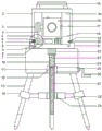
Fig. 1 is a schematic structural diagram of a terrain-assisted mapping apparatus.
FIG. 2 is a schematic view of an arc-shaped slot in a terrain-assisted mapping apparatus.
Fig. 3 is a schematic structural diagram of a housing in a terrain-assisted mapping apparatus.
FIG. 4 is an enlarged view of FIG. 1A of a terrain-assisted mapping apparatus.
In the figure: 1. a base; 2. a housing; 3. a first gear; 4. a belt; 5. a second gear; 6. a first connecting rod; 7. adjusting a knob; 8. a clamping groove; 9. a clamping and connecting plate; 10. a chute; 11. a worm gear; 12. clamping the sliding plate; 13. a telescopic leg; 14. a first fixing plate; 15. a grip; 16. surveying and mapping camera; 17. fixing a rod I; 18. an operation seat; 19. a bolt; 20. a second fixing plate; 21. a turntable; 22. a motor; 23. a spring; 24. a fixed cylinder; 25. a second connecting rod; 26. the rotating rod is held by hand; 27. a worm; 28. a telescopic rod; 29. a fixing ring; 30. a second fixing rod; 31. a baffle plate; 32. an arc-shaped slot; 33. a card slot; 34. surveying and mapping device body.
Detailed Description
The technical solutions in the embodiments of the present invention will be described clearly and completely with reference to the accompanying drawings in the embodiments of the present invention, and it is obvious that the described embodiments are only some embodiments of the present invention, not all embodiments. Based on the embodiments in the present invention, all other embodiments obtained by a person skilled in the art without creative work belong to the protection scope of the present invention.
Referring to fig. 1-3, in the embodiment of the present invention, an auxiliary mapping device for terrain comprises a base 1, a motor 22 is fixedly installed at the upper end of the base 1, a rotary table 21 is fixedly installed at the upper end of the motor 22, the rotary table 21 is installed at the upper end surface of the base 1, a clamping groove 8 is symmetrically formed at the upper end of the rotary table 21, a housing 2 is fixedly installed at the upper end of the rotary table 21, a clamping groove 33 is symmetrically formed at the front end of the upper end of the housing 2, arc-shaped grooves 32 are symmetrically formed at the left and right ends of the housing 2, a second fixing plate 20 is symmetrically arranged at the front and back of the lower end of the arc-shaped grooves 32, the second fixing plate 20 is fixedly installed at the upper end surface of the rotary table 21, a bolt 19 is arranged in the middle of the second fixing plate 20, a second fixing rod 30 is symmetrically and fixedly installed at the left and right upper corners, the upper end of a surveying and mapping device body 34 is fixedly provided with a handle 15, the middle part of the lower end of the surveying and mapping device body 34 is fixedly provided with an operation and control seat 18, the left end of the inside of the surveying and mapping device body 34 is fixedly provided with a first gear 3, the right end of the first gear 3 is fixedly provided with a first fixing rod 17, the middle part of the outside of the first fixing rod 17 is fixedly provided with a surveying and mapping camera 16, the lower part of the first gear 3 is provided with a second gear 5, the first gear 3 and the second gear 5 rotate in the same direction, the outer sides of the first gear 3 and the second gear 5 are provided with a belt 4, the left end of the second gear 5 is fixedly provided with a first connecting rod 6, the first connecting rod 6 penetrates out of the left end surface of the surveying and mapping device body 34, the left end of the first connecting rod 6 is fixedly provided with an adjusting rotating knob 7, the left side and right side of the, clamping slide 12 upper end fixed mounting spring 23, set up spout 10 in the fixed cylinder 24, clamping slide 12 corresponds the setting with spout 10, middle part rear end is equipped with worm wheel 11 in the base 1, worm wheel 11 and worm 27 meshing, worm wheel 11 right-hand member fixed mounting connecting rod two 25, connecting rod two 25 wears out base 1 right-hand member face, connecting rod two 25 right-hand member fixed mounting holds bull stick 26, fixed cylinder 24 outside lower part fixed mounting solid fixed ring 29, gu fixed ring 29 week side fixed mounting a plurality of telescopic link 28, base 1 lower extreme fixed mounting a plurality of flexible stabilizer blade 13, flexible stabilizer blade 13 encircles side middle part fixed mounting fixed plate one 14, telescopic link 28 other end fixed connection fixed plate one 14.
The utility model discloses a theory of operation is:
the utility model discloses during the use, rotate and hold bull stick 26, mesh worm wheel 11 and worm 27, thereby make worm 27 move down, stabilizer blade 13 with stretching out and drawing back is put down, fix base 1, aim at mapping device body 34 and casing 2, 9 joint grooves 8 of joint board, rotating baffle 31 is downward, utilize bolt 19 to make two 20 fixed plates correspond fixedly with mapping device body 34 after that, open motor 22, rotate carousel 21, thereby adjust the position, rotate regulation turn-button 7 after that, thereby utilize belt 4 to make two 5 drive gear one 3 of gear, thereby adjust mapping camera 16 direction, control mapping instrument's angle of turning to.
The above, only be the concrete implementation of the preferred embodiment of the present invention, but the protection scope of the present invention is not limited thereto, and any person skilled in the art is in the technical scope of the present invention, according to the technical solution of the present invention and the utility model, the concept of which is equivalent to replace or change, should be covered within the protection scope of the present invention.
Claims (6)
1. A topographic auxiliary surveying and mapping device comprises a base (1) and is characterized in that a motor (22) is fixedly installed at the inner upper end of the base (1), a turntable (21) is fixedly installed at the upper end of the motor (22), the turntable (21) is arranged on the upper end surface of the base (1), clamping grooves (8) are symmetrically formed in the left and right of the upper end of the turntable (21), a shell (2) is fixedly installed at the upper end of the turntable (21), a surveying and mapping device body (34) is arranged at the upper end of the turntable (21), the surveying and mapping device body (34) is correspondingly arranged with the shell (2), a handle (15) is fixedly installed at the upper end of the surveying and mapping device body (34), a control base (18) is fixedly installed at the middle part of the lower end of the surveying and mapping device body (34), a first gear (3) is fixedly installed at the inner left end of the surveying and mapping device body (34), a first, gear (3) lower part is equipped with gear two (5), and gear (3) and gear two (5) syntropy rotate, gear (3) and gear two (5) outside are equipped with belt (4), gear two (5) left end fixed mounting connecting rod (6), surveying device body (34) left end face is worn out in connecting rod (6), connecting rod (6) left end fixed mounting adjusts turn button (7), surveying device body (34) lower extreme left and right sides symmetry fixed mounting joint board (9), joint board (9) and joint groove (8) are to setting up.
2. The auxiliary topographic surveying and mapping device according to claim 1, wherein the front end of the upper end of the housing (2) is symmetrically provided with clamping grooves (33) at left and right sides, the housing (2) is symmetrically provided with arc-shaped grooves (32) at left and right sides, the lower ends of the arc-shaped grooves (32) are symmetrically provided with a second fixing plate (20) at front and back sides, the second fixing plate (20) is fixedly arranged on the upper end surface of the rotating disc (21), and the middle part of the second fixing plate (20) is provided with a bolt (19).
3. The terrain auxiliary mapping apparatus according to claim 1, wherein a second fixing rod (30) is symmetrically and fixedly installed at the upper left corner and the upper right corner of the housing (2), a baffle (31) is sleeved outside the second fixing rod (30), and the baffle (31) is movably connected with the second fixing rod (30).
4. The auxiliary topographic surveying and mapping device of claim 1, wherein a fixed cylinder (24) is fixedly mounted in the middle of the base (1), a worm (27) is arranged in the fixed cylinder (24), a clamping sliding plate (12) is fixedly mounted at the upper end of the worm (27), a spring (23) is fixedly mounted at the upper end of the clamping sliding plate (12), a sliding groove (10) is formed in the fixed cylinder (24), the clamping sliding plate (12) and the sliding groove (10) are correspondingly arranged, a worm wheel (11) is arranged at the rear end of the middle of the base (1), the worm wheel (11) is meshed with the worm (27), a connecting rod II (25) is fixedly mounted at the right end of the worm wheel (11), the connecting rod II (25) penetrates through the right end face of the base (1), and a hand-holding rotating rod (26) is.
5. A terrain auxiliary mapping apparatus as claimed in claim 4, characterized in that the outside lower part of the fixed cylinder (24) is fixedly provided with a fixed ring (29), and the periphery of the fixed ring (29) is fixedly provided with a plurality of telescopic rods (28).
6. A terrain auxiliary surveying and mapping device as claimed in claim 5, characterized in that a plurality of telescopic supporting legs (13) are fixedly mounted at the lower end of the base (1), a first fixing plate (14) is fixedly mounted at the middle part of the ring side of each telescopic supporting leg (13), and the other end of each telescopic rod (28) is fixedly connected with the first fixing plate (14).
Priority Applications (1)
| Application Number | Priority Date | Filing Date | Title |
|---|---|---|---|
| CN202022415940.0U CN213629591U (en) | 2021-05-31 | 2021-05-31 | Supplementary mapping device of topographic |
Applications Claiming Priority (1)
| Application Number | Priority Date | Filing Date | Title |
|---|---|---|---|
| CN202022415940.0U CN213629591U (en) | 2021-05-31 | 2021-05-31 | Supplementary mapping device of topographic |
Publications (1)
| Publication Number | Publication Date |
|---|---|
| CN213629591U true CN213629591U (en) | 2021-07-06 |
Family
ID=76626176
Family Applications (1)
| Application Number | Title | Priority Date | Filing Date |
|---|---|---|---|
| CN202022415940.0U Active CN213629591U (en) | 2021-05-31 | 2021-05-31 | Supplementary mapping device of topographic |
Country Status (1)
| Country | Link |
|---|---|
| CN (1) | CN213629591U (en) |
-
2021
- 2021-05-31 CN CN202022415940.0U patent/CN213629591U/en active Active
Similar Documents
| Publication | Publication Date | Title |
|---|---|---|
| CN109185668A (en) | One kind fixing bracket with spatial digitizer for large product three-dimensional image acquisition | |
| CN210108368U (en) | Portable building mapping device | |
| CN213629591U (en) | Supplementary mapping device of topographic | |
| CN216566756U (en) | Building engineering surveying and mapping device | |
| CN207864966U (en) | A kind of comprehensive adjustable camera holder with vibration-damping function | |
| CN202791194U (en) | T-shaped filming frame for three-dimensional reduction filming | |
| CN217604986U (en) | Level measurement device is used in hydraulic and hydroelectric engineering construction | |
| CN217130888U (en) | Building engineering cost mapping device | |
| CN213954748U (en) | Extended function analog measurement camera device has | |
| CN214535363U (en) | Photographic arrangement locating rack for geographical mapping | |
| CN211951940U (en) | Oblique photography measuring device for surveying and mapping experiment | |
| CN211121261U (en) | Novel engineering measuring instrument calibration device | |
| CN213481558U (en) | Infrared monitor of convenient control | |
| CN212988355U (en) | Surveying instrument for geological engineering construction | |
| CN214149052U (en) | Intelligent horizontal positioning device for construction site | |
| CN106002944A (en) | Multi-degree-of-freedom manipulator for intelligent robot for over-water filming operation | |
| CN218626125U (en) | Mapping device is used in municipal works construction | |
| CN214275186U (en) | Portable distance measuring device for mine surveying and mapping | |
| CN211331791U (en) | Support frame for laser engraving machine | |
| CN217278951U (en) | RTK device for surveying | |
| CN216385662U (en) | Accurate measuring device for homeland resource management | |
| CN210142453U (en) | Sand table for city planning and construction | |
| CN214996182U (en) | Portable high-precision adjustable circular masonry device | |
| CN214889972U (en) | Surveying instrument support for mine geological engineering construction | |
| CN220398555U (en) | Horizontal measuring instrument for construction engineering investigation |
Legal Events
| Date | Code | Title | Description |
|---|---|---|---|
| GR01 | Patent grant | ||
| GR01 | Patent grant |