CN213561333U - Chip flushing mechanism of machining center - Google Patents
Chip flushing mechanism of machining center Download PDFInfo
- Publication number
- CN213561333U CN213561333U CN202021700502.2U CN202021700502U CN213561333U CN 213561333 U CN213561333 U CN 213561333U CN 202021700502 U CN202021700502 U CN 202021700502U CN 213561333 U CN213561333 U CN 213561333U
- Authority
- CN
- China
- Prior art keywords
- machining center
- flushing mechanism
- operation table
- water tank
- water
- Prior art date
- Legal status (The legal status is an assumption and is not a legal conclusion. Google has not performed a legal analysis and makes no representation as to the accuracy of the status listed.)
- Active
Links
Images


Abstract
The utility model discloses a chip flushing mechanism of a machining center, the utility model relates to a chip flushing mechanism of a machining center, which comprises a machine body and an operation table, wherein the operation table is welded on the upper surface of the machine body, a bracket fixed on the left end and the right end of the operation table is arranged above the operation table, a lead screw is rotatably connected in the middle of the bracket, the surface of the lead screw is in threaded connection with a slider, a spray head is fixedly connected below the slider, a first motor is fixed on the upper left of the bracket, the output end of the first motor is rotatably connected with the left end of the lead screw, and grooves are formed on the front side and the rear side of the operation table; the beneficial effects of the utility model reside in that: remove about driving the shower nozzle through the lead screw and wash, increase washing area, through the hob in the recess with smear metal and the leading-in rose box of flush fluid, the wire net can filter the smear metal, and the flush fluid passes through the water tank and collects, leads to the shower nozzle again through water pump, water pipe and hose again for the flush fluid can cyclic utilization, the water economy resource.
Description
Technical Field
The utility model belongs to the technical field of the smear metal washes technique and specifically relates to a machining center's smear metal washes mechanism is related to.
Background
When cutting metal work piece, can accumulate a large amount of cuttings on the cutting bed, consequently need use washing unit to wash the cutting bed, but traditional washing unit is when washing the cutting bed, lacks the collection device of smear metal, and the metal smear metal is hardly retrieved and is recycled, directly discharges in the smear metal sneaks into waste water after washing, has wasted a large amount of water resources.
SUMMERY OF THE UTILITY MODEL
The utility model aims at the problem that exists with not enough above-mentioned, provide a machining center's smear metal washing mechanism, it drives the shower nozzle through the lead screw and removes and wash, and the area is washed in the increase, and the hob through in the recess is with smear metal and the leading-in rose box of flush fluid, and the wire net can filter the smear metal, and the flush fluid passes through the water tank and collects, leads to the shower nozzle again through water pump, water pipe and hose again for the flush fluid can cyclic utilization, the water economy resource.
In order to achieve the purpose, the adopted technical scheme is as follows:
a chip flushing mechanism of a machining center comprises a machine body and an operation table, wherein the operation table is welded on the upper surface of the machine body, brackets fixed at the left end and the right end of the operation table are arranged above the operation table, a lead screw is rotatably connected in the middle of the brackets, a sliding block is in threaded connection with the surface of the lead screw, a spray head is fixedly connected below the sliding block, a first motor is fixed above the left side of the brackets, the output end of the first motor is rotatably connected with the left end of the lead screw, grooves are formed in the front side and the rear side of the operation table, a screw rod is rotatably connected in each groove, second motors are fixed on the front side and the rear side of the left side of each groove, and the output ends of the second motors are connected with the left end;
the water tank is connected with the lower portion of the right end of the groove in a connected mode, the tail end of the channel is provided with a filter box communicated with the channel, the lower portion of the machine body is provided with a water tank, the lower end of the filter box is connected with and communicated with the upper right portion of the water tank, a water pump is arranged on the lower left portion of the water tank, the right end of the water pump is connected to the left side of the water tank in an inserted mode, a water pipe is connected to the upper end of the water pump in an inserted mode, the tail end of the water pipe is connected to the left side of the support in an inserted mode, the tail end of the.
Preferably, the periphery of the upper surface of the operating platform is fixedly connected with a circle of baffle, and the lower parts of the left end and the right end of the support are fixedly connected with the left side and the right side of the baffle.
Preferably, the channel is bent ninety degrees downwards.
Preferably, a steel wire mesh is arranged below the inner part of the filter box.
Preferably, the left side of the machine body is welded with two support rods, and the water pipe is fixedly penetrated through the two support rods.
Preferably, the base is welded to the lower left of the water tank, and the water pump is fixedly mounted on the upper surface of the base.
By adopting the technical scheme, the beneficial effects are as follows:
the screw rod is driven by the first motor to rotate forwards and reversely, so that the sliding block moves leftwards and rightwards on the surface of the screw rod, the sliding block drives the spray head to move transversely leftwards and rightwards, the spraying range of the spray head is enlarged, the washing efficiency is improved, and the cuttings on the surface of the operating table are washed more thoroughly;
drive the hob through the second motor and rotate for the mixed liquid of flush fluid and smear metal flows right along with the rotation of hob, can filter separation metal smear metal and flush fluid through the wire net in the rose box, is convenient for recycle after the concentrated recovery of smear metal, and surplus flush fluid flows into and collects in the water tank, then forms cyclic utilization in the water pump inlet pipe, has saved the quantity of flush fluid, has practiced thrift the water resource greatly.
Drawings
In order to more clearly illustrate the technical solutions of the embodiments of the present invention, the drawings of the embodiments of the present invention will be briefly described below. The drawings are intended to depict only some embodiments of the invention, and not all embodiments of the invention are limited thereto.
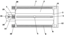
Fig. 1 is a schematic view of the overall front view cross-sectional structure of the present invention;
fig. 2 is a schematic view of the overall top plan structure of the present invention;
fig. 3 is a schematic view of the overall right-side sectional structure of the present invention.
The labels in the figure are: a machine body 1; an operation table 2; a bracket 3; a screw rod 4; a slider 5; a spray head 6; a first motor 7; a groove 8; a screw rod 9; a second electric machine 10; a channel 11; a filter tank 12; a steel wire mesh 13; a water tank 14; a water pump 15; a water pipe 16; a hose 17; a base 18; a strut 19; a baffle 20.
Detailed Description
In order to make the purpose, technical features and technical effects of the technical solution of the present invention clearer, the drawings of the embodiments of the present invention are combined together, and the example solution of the embodiments of the present invention is clearly and completely described.
Referring to fig. 1 to 3, the utility model relates to a chip flushing mechanism of machining center, including organism 1 and operation panel 2, operation panel 2 welds and organism 1 upper surface, be equipped with the support 3 that is fixed in its left and right ends above operation panel 2, and rotate in the middle of the support 3 and be connected with lead screw 4, lead screw 4 surface threaded connection has slider 5, slider 5 below fixedly connected with shower nozzle 6, and support 3 upper left side is fixed with first motor 7, the output of first motor 7 is connected with lead screw 4 left end rotation, and both sides are opened flutedly around operation panel 2, recess 8 inside all rotates and is connected with hob 9, and both sides are all fixed with second motor 10 around recess 8 left side, the output of second motor 10 is connected with hob 9 left end;
a channel 11 communicated with the groove 8 is connected below the right end of the groove 8, a filter box 12 communicated with the channel 11 is arranged at the tail end of the channel 11, a water tank 14 is arranged below the machine body 1, the lower end of the filter box 12 is connected and communicated with the upper right of the water tank 14, a water pump 15 is arranged below the left of the water tank 14, the right end of the water pump 15 is connected to the left of the water tank 14 in an inserting mode, a water pipe 16 is connected to the upper end of the water pump 15 in an inserting mode, the tail end of the water pipe 16 is connected to the left side of the support 3 in an inserting mode, the tail end of the water pipe 16;
a circle of baffle plates 20 are fixedly connected to the periphery of the upper surface of the operating platform 2, the lower parts of the left end and the right end of the support 3 are fixedly connected to the left side and the right side of the baffle plates 20, the channel 11 is bent downwards by ninety degrees, a steel wire mesh 13 is installed below the inner part of the filter box 12, two support rods 19 are welded on the left surface of the machine body 1, a water pipe 16 is fixedly penetrated through the two support rods 19, a base 18 is welded on the left lower part of the water tank 14, and the water pump 15 is;
specifically, before using, a user needs to connect the first motor 7, the second motor 10 and the water pump 15 to an external power supply and start the water pump, a water inlet pipe is arranged at the upper left of the water tank 14, the flushing liquid is injected into the water tank 14 through the water inlet pipe, the flushing liquid is pumped into the water pipe 16 through the water pump 15, the flushing liquid flows into the spray head 6 along the water pipe 16 and the hose 17, the water is sprayed to the surface of the operating platform 2 through the spray head 6, the cuttings on the surface of the operating platform 2 are washed to the periphery, due to the blocking effect of the peripheral baffle 20, the flushing liquid mixed with the cuttings flows into the grooves 8 at the front side and the rear side of the operating platform 2, the screw rod 4 is driven by the first motor 7 to rotate forwards and reversely, so that the slide block 5 moves leftwards and rightwards on the surface of the screw rod 4, the slide block 5 drives the spray head 6 to move leftwards and rightwards, the spraying range of the spray head 6 is enlarged, the washing efficiency is improved, and the cuttings on the surface of the operating platform 2 are washed more thoroughly;
furthermore, flushing fluid and cuttings fall into the groove 8, the screw rod 9 is driven to rotate through the second motor 10, the mixed liquid of the flushing fluid and the cuttings is continuously stirred by the spiral blade on the surface of the screw rod 9, the mixed liquid flows rightwards along with the rotation of the screw rod 9, the mixed liquid flows rightwards into the channel 11 and flows into the filter box 12 through the channel 11, the mixed liquid falls downwards in the filter box 12, the cuttings are intercepted through the filtering effect of the surface holes of the steel wire mesh 13, the flushing fluid continues to fall downwards along the holes of the steel wire mesh 13 until flowing into the water tank 14, the metal cuttings and the flushing fluid can be filtered and separated through the steel wire mesh 13 in the filter box 12, the cuttings are conveniently recycled after being concentrated and recovered, the residual flushing fluid flows into the water tank 14 to be collected, and then is pumped into the water pipe 16 through the water pump 15 to form recycling, and the using amount of, greatly saving water resources.
In the present specification, each embodiment is described with emphasis on differences from other embodiments, and the same or similar parts between the embodiments may be referred to each other. Unless otherwise defined, technical or scientific terms used in the present embodiments should have the ordinary meaning as understood by those having ordinary skill in the art to which the present invention belongs.
Exemplary embodiments of the present invention have been described in detail with reference to the preferred embodiments, however, it will be understood by those skilled in the art that various modifications and changes may be made to the above specific embodiments without departing from the scope of the present invention, and various combinations of the technical features and structures of the present invention may be implemented without departing from the scope of the present invention, which is defined by the appended claims.
Claims (6)
1. A chip flushing mechanism of a machining center comprises a machine body (1) and an operation platform (2), wherein the operation platform (2) is welded with the upper surface of the machine body (1), and is characterized in that:
the automatic feeding device is characterized in that supports (3) fixed at the left end and the right end of the operation table (2) are arranged above the operation table, a screw rod (4) is rotatably connected in the middle of each support (3), a sliding block (5) is connected to the surface of each screw rod (4) in a threaded manner, a spray head (6) is fixedly connected to the lower portion of each sliding block (5), a first motor (7) is fixedly arranged at the upper left portion of each support (3), the output end of each first motor (7) is rotatably connected with the left end of each screw rod (4), grooves (8) are formed in the front side and the rear side of the operation table (2), a screw rod (9) is rotatably connected inside each groove (8), second motors (10) are fixedly arranged on the front side and the rear side of the left side of each groove (8), and the output ends of the second motors (;
the water tank type sprayer is characterized in that a channel (11) communicated with the groove (8) is connected to the lower portion of the right end of the groove (8), a filter box (12) communicated with the channel is mounted at the tail end of the channel (11), a water tank (14) is arranged below the machine body (1), the lower end of the filter box (12) is connected and communicated with the upper right portion of the water tank (14), a water pump (15) is arranged at the lower left portion of the water tank (14), the right end of the water pump (15) is connected and connected to the left side of the water tank (14), a water pipe (16) is connected and connected to the upper end of the water pump (15), the tail end of the water pipe (16) is connected and connected to the left side of the support (3), the tail end of the water pipe (16) penetrates through the inner wall of the left side of the support (3), a hose.
2. A chip flushing mechanism of a machining center according to claim 1, characterized in that: the periphery of the upper surface of the operating platform (2) is fixedly connected with a circle of baffle (20), and the lower parts of the left end and the right end of the support (3) are fixedly connected with the left side and the right side of the baffle (20).
3. A chip flushing mechanism of a machining center according to claim 1, characterized in that: the channel (11) is bent downwards by ninety degrees.
4. A chip flushing mechanism of a machining center according to claim 1, characterized in that: and a steel wire mesh (13) is arranged below the inner part of the filter box (12).
5. A chip flushing mechanism of a machining center according to claim 1, characterized in that: two supporting rods (19) are welded on the left side of the machine body (1), and the water pipe (16) penetrates through and is fixed with the two supporting rods (19).
6. A chip flushing mechanism of a machining center according to claim 1, characterized in that: a base (18) is welded on the lower left side of the water tank (14), and the water pump (15) is fixedly installed on the upper surface of the base (18).
Priority Applications (1)
| Application Number | Priority Date | Filing Date | Title |
|---|---|---|---|
| CN202021700502.2U CN213561333U (en) | 2020-08-15 | 2020-08-15 | Chip flushing mechanism of machining center |
Applications Claiming Priority (1)
| Application Number | Priority Date | Filing Date | Title |
|---|---|---|---|
| CN202021700502.2U CN213561333U (en) | 2020-08-15 | 2020-08-15 | Chip flushing mechanism of machining center |
Publications (1)
| Publication Number | Publication Date |
|---|---|
| CN213561333U true CN213561333U (en) | 2021-06-29 |
Family
ID=76555012
Family Applications (1)
| Application Number | Title | Priority Date | Filing Date |
|---|---|---|---|
| CN202021700502.2U Active CN213561333U (en) | 2020-08-15 | 2020-08-15 | Chip flushing mechanism of machining center |
Country Status (1)
| Country | Link |
|---|---|
| CN (1) | CN213561333U (en) |
-
2020
- 2020-08-15 CN CN202021700502.2U patent/CN213561333U/en active Active
Similar Documents
| Publication | Publication Date | Title |
|---|---|---|
| CN208357368U (en) | One kind being used for the clean supersonic wave cleaning machine of industrial part | |
| JP3240287U (en) | Environmentally friendly circulation dust remover | |
| CN213561333U (en) | Chip flushing mechanism of machining center | |
| CN206083838U (en) | Machining suppresses full -automatic burring high pressure cleaner of power | |
| CN218854977U (en) | Electro-hydraulic hammer cleaning device | |
| CN216441201U (en) | Belt cleaning device for water pump foundry goods | |
| CN218188706U (en) | Washing tower with high-efficient flue gas dust fall function | |
| CN210454765U (en) | Water saving fixtures of intelligence car washer | |
| CN204911750U (en) | Material machine is washed to diamond micropowder overflow formula | |
| CN210586067U (en) | Office product production is polished and is used washing unit | |
| CN210252748U (en) | Remove sprinkler of formaldehyde remover | |
| CN209793261U (en) | Washing unit for machining center convenient to clearance iron fillings | |
| CN207432022U (en) | A kind of inner container of electric cooker production sand-blasting machine | |
| CN213817683U (en) | Photovoltaic module with self-cleaning mechanism | |
| CN219632070U (en) | Crankshaft internal thread flushing machine | |
| CN212504772U (en) | Vegetable oil filter cloth and filter paper washing and recovering device | |
| CN217626706U (en) | Tension control structure of multi-roll washing device for cotton pulp | |
| CN220006298U (en) | Antifouling numerical control wire cut electrical discharge machining bed | |
| CN216297892U (en) | Machine of taking lead is processed to screw | |
| CN218797596U (en) | Surface cleaning device for bicycle processing plates | |
| CN214516614U (en) | Microwave digestion instrument inner tank cleaning device | |
| CN217572098U (en) | Water-cooling heat sink of milling machine | |
| CN212270849U (en) | Trash remover with automatic washing tooth rake structure | |
| CN215031379U (en) | Novel automatic shovel board of negative pole copper device | |
| CN210076520U (en) | Turnip water conservation cleaning machine |
Legal Events
| Date | Code | Title | Description |
|---|---|---|---|
| GR01 | Patent grant | ||
| GR01 | Patent grant | ||
| TR01 | Transfer of patent right |
Effective date of registration: 20210811 Address after: 116000 No. 4, Huaihe Zhongsan Road, Dalian Economic and Technological Development Zone, Dalian City, Liaoning Province Patentee after: Dalian Yixin precision mould Co.,Ltd. Address before: 338000 building 4, Yongsheng international community, 32 Ping'an Road, Yushui District, Xinyu City, Jiangxi Province Patentee before: Liu Bingyu |
|
| TR01 | Transfer of patent right |